 Open Access Article
Creative Commons Attribution 3.0 Unported Licence
Mechanically robust, thermally stable, highly transparent superhydrophobic coating with low-temperature sol–gel process
Yanping Zhangab,
Binghai Dong *ab,
Shimin Wang*ab,
Li Zhaoab,
Li Wanab and
Erjing Wangab
aHubei Collaborative Innovation Center for Advanced Organic Chemical Materials, China. E-mail: wwwdbh@163.com; shiminwang@126.com
bKey Laboratory for the Green Preparation and Application of Functional Materials, Ministry of Education, Hubei Key Laboratory of Polymer Materials, Faculty of Materials Science and Engineering, Hubei University, Wuhan 430062, PR China
First published on 9th October 2017
Abstract
The wetting behavior of transparent superhydrophobic surfaces has attracted much attention in our daily life as well as in engineering applications. Optically transparent superhydrophobic silica films were synthesized by sol–gel method. The coating was formed by in a solution containing silica nanoparticles and silicic acid, in which the silica nanoparticles and silicic acid had different proportions to modulate the roughness of the coating. Comparing with the HMDZ modified films (140 ± 2°), the films modified by TMCS showed very high water contact angle (164 ± 2°), which indicating the excellent waterproof behavior of the films. When the TMCS modified films were heated at temperature above 350 °C and 400 °C, it became superhydrophilic. The transmittance of coated glasses were above 80% for wavelengths at 400–800 nm. Moreover, the properties of the film were almost unchanged after acid corrosion and immersion in salt solution, and still retained the superhydrophobicity. Even after the impact of water flow and sand impact abrasion, it can still maintain good performance of superhydrophobicity.
1. Introduction
An excellent non-wetting surface that exhibits a contact angle (CA) above 150° and sliding angle (SA) below 10° is referred to as a superhydrophobic surface.1–4 Surface wettability is one of the most important properties of solid surfaces. It is closely related to basic science theory and practical applications. The phenomenon that water droplets cannot adhere to such a surface but roll off is advantageous for potential applications in self-cleaning,5,6 anti-fogging,7,8 oil–water separation,9,10 and anti-icing.11,12 Transparent superhydrophobic surfaces expand the range of potential applications to optical fields such as windshields for automobiles, solar-cell panels, safety goggles, and windows for electronic devices,13–15 and therefore have recently attracted more and more attention. Recently, the increasing interest in energy efficiency has prompted research in developing coatings that are both self-cleaning and transparent.16–24 For example, the desire for alternative energy sources has made significant progress in the development of solar cells. However, the build up of dust, dirt, pollution, wet-snow, tree saps and bird droppings on the surface of the solar panels can block the sunlight from reaching the solar cells, therefore, dramatically decreasing the efficiency and output of the solar energy. Transparent, superhydrophobic coating will also be very useful for the protection of buildings, clothes, papers, and art pieces.Accordingly, the synthesis of superhydrophobic films requires the combination of surface chemical modification and the enhancement of surface roughness. Since the microscopic structure of superhydrophobic coatings strongly scatter visible light, high transparency in the visible region and superhydrophobic properties are mutually exclusive in principle. Increasing the surface roughness can enhance the hydrophobicity, but reduce the transparency due to light scattering losses. Mie scattering is responsible for the blurring of superhydrophobic surfaces.22 In order to minimize Mie scattering, surface roughness must be reduced below the wavelength of incident light. Sub-100 nm with lower scattering intensity has been proved to be able to prepare superhydrophobic surfaces with high visible light transparency. Therefore, in order to make transparent superhydrophobic surfaces, particular attention should be paid to controlling the surface roughness size. Therefore, controlling the surface roughness to an appropriate value is the main task to meet the both of requirements.25–27
The practical application of superhydrophobic surfaces was limited by some preparation conditions, multi-step processes, expensive low surface energy materials, etc. Most of the bare-fluorinated materials have the expensive price and often are vulnerable to environment attacks while causing ozone shield to crack more seriously. Hence, the other hydrophobic group must be replaced for good use. Whereas fluorine-containing bonds (–CF3) have lower surface tension than –CH3, replacing –CF3 with –CH3 chemistries need introducing more stringent requirements for transparent superhydrophobic surface.28 It is usually introduced as supplementary end-capping by means of trimethylchlorosilane (TMCS) and hexamethyldisilazane (HMDZ)29 for modifying the hydrophilic groups to enhance hydrophobic properties of the as-prepared surfaces.
Recently, many artificial surfaces have been investigated with regard to their chemical, mechanical,19,30 and thermal stability.31 A 10 min of ultrasonication damage on a superamphiphobic coating resulted in a rapid decrease in the contact angle and an increase in the contact angle hysteresis.32 Deng et al.24 reported a simple way to fabricate robust transparent superamphiphobic coatings using candle soot as template followed by ammonia-catalyzed CVD of tetraethoxysilane (TEOS). The coatings could withstand water-drop impact, sand abrasion test and tape peeling test. Yokoi et al.33 sprayed 1H,1H,2H,2H-perfluorooctyl-triethoxysilane (PFOTS) modified SiO2 nanoparticles onto a polyester mesh, which had been etched by alkaline followed by CVD of 1H,1H,2H,2H-perfluorodecyltrichlorosilane (PFDTS), obtaining a highly transparent superhydrophobic thin film. The thin film showed enhanced abrasion resistance. Undoubtedly, the mechanical stability, especially the adhesive strength between the coating and the substrate determines the application of the coating. In most cases, however, high-temperature treatment was commonly used to enhance the robustness of thin films, which limits their practical applications on most polymer substrates having low glass transition or decomposition temperatures and being unable to withstand any high-temperature treatment. For industrial implementation, the coatings must be easily fabricated at low energy consumptions and must be durable during services. Moreover, the improvement of mechanical robustness was mostly at the expense of high transmittance and superhydrophobicity. Therefore, the coatings via a low-temperature fabrication having superhydrophobic characteristic and possessing mechanical stability of anti-acid/alkali damage and water flow impact and sand impact abrasion are less well studied so far.16,24,32
In this study, a durable transparent superhydrophobic SiO2-based coating was processed onto glass substrates by a sol–gel process at low-temperature. SiO2-based surfaces went through the conversion of the hydrophilic surface to superhydrophobic (CA > 150°) by TMCS derivatization and in ultra hydrophobic (CA > 120°) by HMDZ derivatization. Moreover, the obtained coating exhibited stable superhydrophobicity under extreme conditions of low or high temperature, water flow impact and sand impact abrasion. The formation of nonfluorinated superhydrophobic surfaces at low temperatures is important for the fabrication of environmentally friendly coatings.
2. Experimental sections
2.1. Materials
Tetraethoxysilane (TEOS, 98%), ethanol, n-hexane, hydrochloric acid (HCl, 36–38%), silica dioxide (SiO2, 98%, average diameter 15 ± 5 nm) trimethylchlorosilane (TMCS, 97%) 1,1,1,3,3,3-hexamethyldisilazane (HMDS, 98%) were purchased from Aladdin Industrial Co., Ltd. All chemicals were analytical grade reagents and were used without further purification. Deionized water (resistivity ∼ 18 MΩ cm) was used in this study.2.2. Preparation of silica solution
The coating solution was prepared by the sol–gel method using HCl aqueous solution as the catalyst.34 In a typical production, hydrochloric acid was added to deionized (DI) water for preparing (pH = 2) HCl aqueous solution. TEOS and (pH = 2) HCl aqueous solution were mixed together at a molar ratio of 1![[thin space (1/6-em)]](https://www.rsc.org/images/entities/char_2009.gif) :
:![[thin space (1/6-em)]](https://www.rsc.org/images/entities/char_2009.gif) 4.6 with a magnetic stirrer for 2 h, giving rise to silicic acid, Si(OH)4. Then, 15 nm silica powders were dispersed in ethanol (200 mL) at different content using a magnetic stirrer and ultrasonic vibrator for 30 min. Silicic acid was then added to the silica/ethanol solution using a magnetic stirrer and ultrasonic vibrator for 2 h. The composition of each sol–gel solution are list in Table 1.
4.6 with a magnetic stirrer for 2 h, giving rise to silicic acid, Si(OH)4. Then, 15 nm silica powders were dispersed in ethanol (200 mL) at different content using a magnetic stirrer and ultrasonic vibrator for 30 min. Silicic acid was then added to the silica/ethanol solution using a magnetic stirrer and ultrasonic vibrator for 2 h. The composition of each sol–gel solution are list in Table 1.
| Sr no. | Silica particle | Ethanol (mL) | Si(OH)4 (mL) |
|---|---|---|---|
| 1 | 1.5 g | 200 | 3 |
| 2 | 3 g | 200 | 6 |
| 3 | 4.5 g | 200 | 9 |
2.3. Formation of superhydrophobic coating
The substrate used for this study was transparent plain glass (microscope slides) of 25 × 25 × 1 mm. A chemical substrate cleaning procedure was ultrasonicated for 30 min with HCl (0.1 M), NaOH (0.1 M), deionized water, ethanol and iso-propylalcohol, respectively, in turn to remove the surface contamination and dust. All glass substrates were dried at 50 °C for 2 h before coating. In order to expose more hydroxyl to the surfaces of the glass, the clean glasses were placed in the UV cleaning machine for 20 min. Then the uniform films were prepared at a spinning rate of 1000 rpm for 9 s and 2500 rpm for 30 s while spinning the mixing solution onto the clean substrates. All coating processes were conducted in ambient atmosphere (approximately 25 °C, 70% relative humidity). And, all the coated glasses were allowed to cure at 80 °C for 4 h, 120 °C for 6 h. This curing step was used to form a dense three-dimensional structure by thermally-induced self-condensation reactions within the coating material as hydroxide groups were removed from the remaining silanol molecules, and the structure was bonded to the underlying substrate. Finally, the coated substrate by dipping in 4 v/v% TMCS hexane solution by solvothermal method at 80 °C for 8 h. Then all the coated glass substrates were annealed at 120 °C for 4 h to solidify the nano-coating and remove the unreacted solvent.2.4. Characterization
The surface morphology of coating was examined by field emission scanning electron microscopy (FE-SEM, Jeol JEM, 6510LV). The samples were coated with a thin gold layer to improve electrical conductivity before SEM observations. The samples for FT-IR characterization are prepared by removing film from the substrate by using stainless steel knife. Sample powder was mixed with KBr and a homogeneous mixture formed with a mortar and pestle, then scanned in frequency range from 450 to 4000 cm−1. X-ray photoelectron spectroscopy (XPS) was carried out on a Thermo Scientific K-alpha photoelectron spectrometer with the monochromatic Al–KCl source to identify the chemical constituents. The transmission spectra of the coated glass substrate were obtained by a UV-vis spectrophotometer (UV-3600, Shimadzu). A atomic force microscope (AFM, Nanoscope-IIIa) was employed to get the information of surface roughness of film. Water contact angle (WCA) samples were measured at room temperature on the JC2000CS measuring instrument equipped with CCD camera. Each contact angle measurement was repeated three times at different places on each sample and the mean value was reported.3. Results and discussion
3.1. Reaction mechanism in preparation of transparent superhydrophobic coatings
The fabrication process of the coating on the glass substrate is shown in Fig. 1. The first step of the whole process was hydrolysis of TEOS to form silicic acid.35 Since the condensation reaction of the silicic acid and Si(OH)4 is easy to carry out, the monomer silicic acid has never been isolated. The results showed that the monomer silicate was only in dilute aqueous solution. In addition, the behavior of silicic acid showed the maximum temporary stability in the absence of salt, and the gel time was the longest when the pH = 1.5–3.36 Therefore, by adding hydrochloric acid, the pH value of the TEOS and the excess deionized water can be controlled at 2. Silica nanoparticles in ethanol solvents are dispersed in sol–gel solutions with the addition of the silicic acid due to the solvent effect. That is to say, silicic acid can cover the surface of silica by forming hydrogen bonds on the silicon substrate by pairs of Si–OH groups. When the sol–gel solution spreads on the glass substrate, the silica covered with the silicic acid was also attracted onto the glass substrate through hydrogen bond formation. Then, the hydrogen bond in a pair of Si–OH groups transformed to the covalent bond of Si–O–Si through a baking dehydration process. Finally, the TMCS was deposited onto the rough silica-based film through dehydration during baking.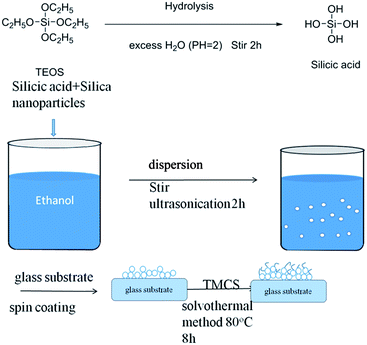 | ||
| Fig. 1 Schematic representation of the approach to deposit a superhydrophobic coating on the glass substrate. | ||
3.2. Effect of different silylating agent and percentage of silylating agent
In principle, the HMDZ and TMCS react with hydroxyl groups on the silica surface and could be represented by the following chemical reactions:Surface modification by HMDZ:
 | (4) |
Surface modification by TMCS:
 | (5) |
However, from the experimental observations, it seems that even if the nonpolar groups end-capping, the film surfaces are remain the same, while their physical and chemical properties will change in a wide range, depending on the nature of the used silicon agent.37
The content of SiO2 nanoparticles was varied from 1 to 3% keeping the silylation period constant at 8 h. From the water contact angles of the hydrophobic films for different contents of SiO2 nanoparticles given in Table 2, it could be seen that the contact angle increases with increasing in content of SiO2. However, for the TMCS modified-silica films, it observed that the contact angle increases from 140° to 164° with an increase in the content of SiO2. For the HMDZ modified silica films, it showed that with an increase in the content of SiO2, contact angle increases from 130° to 148°. In addition to the above facts, it has been observed that the main cause of the difference in the physical properties of silica films are the different reaction kinetics of the silylating agents. In the case of TMCS, it can directly react with the silica surface to yield a nonpolar surface and HCl is given as a reaction product (eqn (5)). However, in the case of HMDZ the reaction mechanism shown by eqn (4) and may involve a two-step reaction as in the following;38
![[triple bond, length as m-dash]](https://www.rsc.org/images/entities/char_e002.gif) Si–OH + HN(Si–(CH3)3)2 → Si–OH + HN(Si–(CH3)3)2 → ![[triple bond, length as m-dash]](https://www.rsc.org/images/entities/char_e002.gif) Si–O–Si–(CH3)3 + H2N–Si–(CH3)3. Si–O–Si–(CH3)3 + H2N–Si–(CH3)3.
| (6) |
| Sr no. | Content of SiO2 | Effect of HMDZ (4%) on WCA | Effect of TMCS (4%) on WCA |
|---|---|---|---|
| 1 | 1% | 130° | 140° |
| 2 | 2% | 142° | 154° |
| 3 | 3% | 148° | 164° |
Again the trimethylaminosilane, the byproduct of the above reaction can interact with the Si–OH groups as shown in the following reaction;
![[triple bond, length as m-dash]](https://www.rsc.org/images/entities/char_e002.gif) Si–OH + H2N–Si–(CH3)3 → Si–OH + H2N–Si–(CH3)3 → ![[triple bond, length as m-dash]](https://www.rsc.org/images/entities/char_e002.gif) Si–O–Si–(CH3)3 + NH3. Si–O–Si–(CH3)3 + NH3.
| (7) |
This indicates that the reaction rate of HMDZ with the silica surface is low as compared to the TMCS.
3.3. FT-IR spectra analysis and XPS spectra of silica-based nanocoating before and after TMCS modification
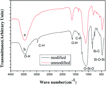
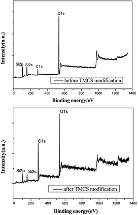
The chemical composition of the films deposited on a glass substrate was investigated by the FT-IR spectroscopy using the KBr method in transmission mode. The FT-IR spectra of the as bare silica and TMCS (4%) modified films are shown in Fig. 2(a) and (b). The FT-IR spectra of the films should have been due to the hydrolysis of methoxy groups of the TEOS monomers to make Si–OH groups, the polymerization of the Si–OH groups to make the siloxane bonds and during the surface modification, the –H's of the surface OH's of silica films are replaced by –Si–(CH3)3 groups resulting in dehydroxylation of the film surface leading to hydrophobicity. The absorption band of the –OH around 3400 cm−1 and that of water adsorbed around 1600 cm−1 are decreased after modifying the surface with TMCS.39 The FT-IR spectra of unmodified and TMCS modified silica films shows a very strong absorption band at 1096 cm−1 is due to the stretching vibration of Si–O–Si bridges.40 The absorption bands observed at around 1400 cm−1 is due to stretching and bending of C–H bonds and the peaks observed at 847 cm−1 are due to the Si–C bonds.41 The number of C–H and Si–C peaks are quite notable for the TMCS modified films, which are found to be less for the unmodified silica. The Si–OH band present in all the FT-IR spectra reveals that surface hydroxyls still exist, even though the materials show the strong hydrophobic behavior. In order to further elaborate the superhydrophobic mechanism of TMCS modified coatings, the chemical composition of TMCS modified coatings and unmodified coating were examined through XPS analysis (showed on Fig. 3). The surface atomic ratios of silica before and after TMCS treatment, summarized in Table 3, were calculated from peak area ratios. After treated by TMCS, the surface atomic ratio of C increases from 17.7% to 53.38%, while the surface atomic ratios of Si and O decrease from 28.47%, 53.83% to 10.8%, 35.83%, respectively. The results summarized in Table 3 are in good conformity with the conclusion of XPS spectra above. This high concentration of carbon endues TMCS modified coatings with a low surface energy in conjunction with hierarchical structure that entrusts their superhydrophobicity.| Atomic ratio | C 1s | O 1s | Si 2p |
|---|---|---|---|
| Before TMCS treatment | 17.7% | 53.83% | 28.47% |
| After TMCS treatment | 53.38% | 35.83% | 10.8% |
3.4. Micrographs analysis of the various silica coatings modified by TMCS
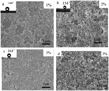
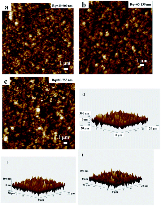
A scanning electron microscopy (SEM) image of the surface topology obtained with different content modified-silica nanoparticles containing layer is shown in Fig. 4. As is clearly visible, two different levels of nano texturing are present, being a key characteristic in the creation of superhydrophobic surfaces. As shows on Fig. 4, different content of SiO2 coating surface has similar apparent morphology, in addition, the density of coating on the surface film is unique because of the different content. From Fig. 4 as we can see, the percentage of 1 wt% of the silica coating surface has some bare place, which is failed to completely cover the glass surface. And the surface roughness is small, thus causing the surface contact angle is smaller. By contrast, the percentage of 2 wt% and 3 wt% of the coated surface formed a relatively dense thin film, causing the surface roughness increased with the increase of content, while accompanying with increasing contact angle. As Fig. 4(d) shows, the coating surface is made up of dozens of nano silicon dioxide particles unordered accumulated, it forms a range of roughness of micro–nano structure of the porous layer, which is the necessary conditions for forming superhydrophobicity. It is easy to understand that this behavior is related to the film morphology and the intrinsic low surface energy of silica particles, which originates from the chemical properties of the trimethyl groups grafted onto the surface of the particles. These species produce asymmetric molecular forces that cause water repulsion. To better reveal the effect of surface texturing on ultra water repellency, an AFM characterization (from Fig. 5) has also been done, it can be observed from the 2D AFM images that the surfaces of both substrates have been coated homogeneously by spinning coating, the height profile curves verify the results of 3D AFM images, from which frequently fluctuant height profiles can be seen for different content silica-coating. The rms roughness value of different content silica-coating can be calculated from the software, the rms roughness values were increased with the silica content. And all the rms roughness values (∼40–90 nm) are sub-100 nm roughness. It can be deduced that silica nanoparticles which deposit different content are responsible for the hierarchical roughness. The result is corresponding with SEM.3.5. Transparency measurement of silica-based film modified by TMCS
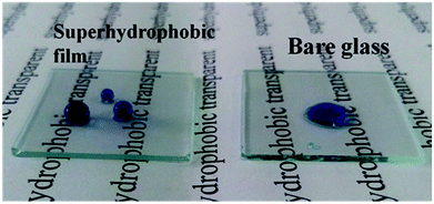
Transparency is an important feature of superhydrophobic surface; for example, transparent films are the basic requirement when superhydrophobic surface are applied to windows and solar cells. However, the preparation of transparent superhydrophobic films is not simple, because surface roughness leads to a decrease in transparency due to the scattering of Mie. Therefore, in order to avoid the surface roughness caused by fuzzy, one should accurately control the surface roughness, surface roughness must be large enough to show the superhydrophobicity, but should be as low as possible to maintain transparency. These stringent limitations make it difficult to prepare superhydrophobic and transparent films on glass substrates. The transmittance is related to refraction of a transparent medium by the Fresnel's equation and the index of refraction of a material is related to its density.42 Optical characteristics of such coated superhydrophobic surfaces have also been tested by means of transmittance measurements. In Fig. 6 the transmission spectra of several coated samples are reported and compared to the spectrum of an uncoated sample. From Fig. 6(a), the transmittance of surfaces coated with different content silica nanoparticles is decreased with the increasing of content silica nanoparticles. These decrease in transmittance when compared with uncoated substrate is due to the deposition of silica nanoparticles with roughness greater than the uncoated glass, which leads to Mie scattering effect. In addition to surface roughness, the constituents and thickness of the film may also be the determining factor of transparency. It can be seen the relationship of transmittance and thickness from Fig. 6(b). The good readability of the script underneath the coated glass substrates reflected their high transparency, and the superhydrophobicity is demonstrated by almost sphere blue-colored water droplets in Fig. 7. In our coatings, the surface structure is a composite consisting of air and solid components. Therefore, a proper model was employed using effective medium approximation to calculate refractive index (RI) as follows:43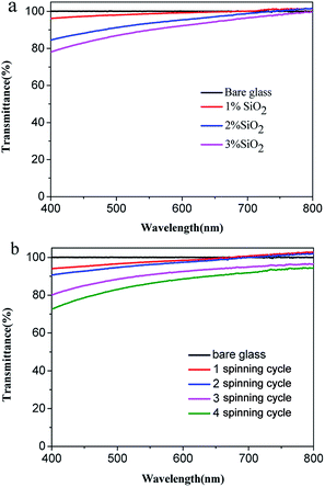 | ||
| Fig. 6 (a) Optical transmittance spectrums of the various silica-coated glass substrates. (b) Optical transmittance spectrums of the various spinning cycle with 2 wt% silica-coated glass substrates. | ||
The reflectivity is explained with Fresnel equation:
Table 4 showed the relationship between silica content and roughness, contact angle, and transparency. The roughness of film become more and more bigger, due to the increasing of silica content, which lead to the increasing of contact angle, as well as the decreasing of transparence. However, all the film roughness were below 100 nm, so that all the film has highly transparence.
| Sr no. | Content of SiO2 [wt] | Roughness [nm] | Contact angle [°] | Transparence at 550 nm [%] |
|---|---|---|---|---|
| 1 | 1 wt% | 49.909 nm | 140° | 98.7% |
| 2 | 2 wt% | 65.159 nm | 154° | 93.5% |
| 3 | 3 wt% | 80.755 nm | 164° | 89.9% |
3.6. Thermal stability chemical stability of silica-based nanocoating modified by TMCS
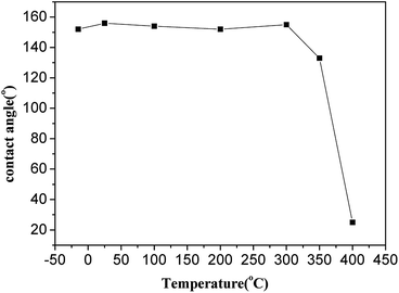
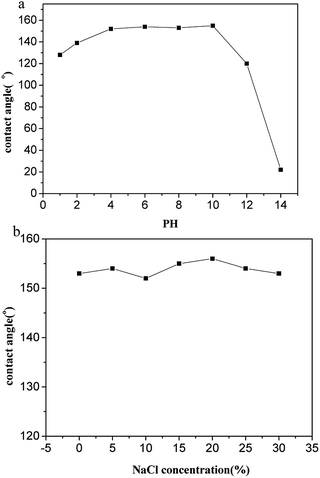
For outdoor application superhydrophobic surfaces, the long-term stability under rigorous conditions is essential. Thus, the temperature stability of the coatings is carried out from −18 to 400 °C for 2 h. As illustrated in Fig. 8, the samples keep superhydrophobicity with WCA > 150°, demonstrating excellent thermal stability when temperature from −15 to 300 °C, it indicates excellent high-temperature stability of the silica-base surface when the temperature below 300 °C. However, the WCA of the surface decreases a little when the temperature over 300 °C, the WCAs starts to decrease when the temperature ramped up further, and the wettability change to superhydrophilicity after calcination at 400 °C due to removal of low surface energy material. As expected, when the organic moiety is removed by a thermal treatment in air, the hydrophobic character is irreversibly changed to hydrophilic. When the TMCS modified films are cured at temperatures higher than 350 °C and 400 °C, this is due to the fact that, above these temperatures the Si–(CH3)3 groups get oxidized into Si–OH groups which leads to the adsorption of water.The chemical stability of functional materials is of great significance for application in the aquatics industry. Two measurements are used to evaluate the chemical stability of the as-prepared superhydrophobic glass in an aqueous solution, including acid/alkali corrosion and salt solution immersion. The as-prepared glasses are immersed in an aqueous solution with different pH values. For the glass immersed in an acid solution, the WCA decreases with the increasing of acidity but still maintains hydrophobic performance with WCA over 120° showed on Fig. 9(a), on the contrary, the WCA of the glass immersed in alkali solution causes obvious deterioration and the superhydrophobicity disappears after immersion in aqueous solution with pH value over 13. However, the surface still keep superhydrophobicity with WCA over 150° after one month of immersion in aqueous solution with pH value from 4 to 10. The salt solution stability is tested with the samples immersed in sodium chloride (NaCl) solutions with concentration from 0 to saturation. The WCA is measured to assess the salt tolerance. As showed in Fig. 9(b), no obvious change of WCA is observed after one week immersion and the as-prepared glass keep its superhydrophobicity with WCA > 150°, demonstrating excellent stability to salt solution.
3.7. Mechanical robustness of the silica-based nanocoating modified by TMCS
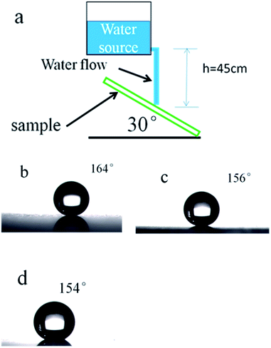
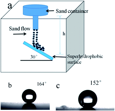
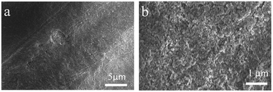
Mechanical robustness is essential for practical applications. However, due to its poor mechanical properties, elaborately designed microstructures of superhydrophobic films are susceptible to damage. Reported in literature, waterfall and sand grain abrasion tests are commonly used to investigate the mechanical robustness of superhydrophobic thin films.46–48 Water flow is applied to impact the superhydrophobic surface from a height of 45 cm (the velocity is about 4 m s−1) and a tilt angle of 30°. Fig. 10 shows that the WCA value of the sample decreased with the increasing of water, but keeps the superhydrophobicity with WCA over 150° up to 20 L of water (shown on Fig. 10(b) and (c)). A sand impact abrasion test is also performed to investigate the mechanical resistance to sand impact abrasion. 40 g sand impact abrasion from a 50 cm height. 100–300 μm sized grains have velocity of 8.7 km h−1 just before impingement. The WCAs of coated glass substrate before and after sand impact abrasion test are shown in Fig. 11(b) and (c), respectively. After sand impact abrasion, the thin film still shows superhydrophobicity. From Fig. 12(a) we can see, it is noted that the thin film was nearly intact, only few parts of the silica nanoparticles are exposed which had been impinged by sands. The damages may account for the slight decrease in superhydrophobicity. However, the major thin film still shows a micro–nano scale morphology showed on Fig. 12(b), which endows the thin film superhydrophobicity. This very strong adhesion property of the nanocomposite coating are attributed to the fact that hydroxyl groups in the SiO2-coated film interact with the other hydroxyl groups on the surface of the glass substrate.4. Conclusion
We used the hydrolytic properties of tetraethoxysilane hydrolysis to obtain silicic acid as a coupling agent. Dispersion of SiO2 nanoparticles in ethanol was performed by ultrasonication. The silica-base coating of nanoscale roughness was coated with the sol–gel method on the glass surface. After being further coated with a low surface energy material TMCS, the silica-based coating was superhydrophobic and transparent. Furthermore, by controlling surface roughness of resultant coatings, it is possible to achieve transparent superhydrophobic coating having excellent wetting behavior properties with high optical transmission, thermal stability, chemical stability and mechanical robustness. The experimental results clearly showed that a simple method such as the sol–gel process resulted in superhydrophobic silica films without using fluoroalkyl compounds at low temperature.Conflicts of interest
There are no conflicts to declare.Acknowledgements
The work was supported by the key projects of Department of Hubei Provincial Science and Technology (2016AAA034), Natural Science Foundation of Hubei Province (2016CFB507). This work was also supported by the Natural Science Foundation of China (51572072, 51603063 and 21402045).References
- T. S. Wong, S. H. Kang, S. K. Tang, E. J. Smythe, B. D. Hatton, A. Grinthal and J. Aizenberg, Nature, 2011, 477, 443 CrossRef CAS PubMed.
- K. Koch, B. Bhushan, Y. C. Jung and W. Barthlott, Soft Matter, 2009, 5, 1386 RSC.
- X. J. Feng and L. Jiang, Adv. Mater., 2006, 18, 3063 CrossRef CAS.
- H. Y. Erbil, A. L. Demirel, Y. Avcı and O. Mert, Science, 2003, 299, 1377 CrossRef CAS PubMed.
- M. Ramezani, M. R. Vaezi and A. Kazemzadeh, Appl. Phys. A, 2015, 119, 845 CrossRef CAS.
- S. Nishimoto and B. Bhushan, RSC Adv., 2013, 3, 671 RSC.
- X. Li and J. He, ACS Appl. Mater. Interfaces, 2012, 4, 2204 CAS.
- J. Zhao, A. Meyer, L. Ma and W. Ming, Chem. Commun., 2013, 49, 11764 RSC.
- Y. Li, X. Zhu, B. Ge, X. Men, P. Li and Z. Zhang, Appl. Phys. A, 2015, 120, 949 CrossRef CAS.
- B. Ge, X. Zhu, Y. Li, X. Men, P. Li and Z. Zhang, Appl. Phys. A, 2015, 121, 1291 CrossRef CAS.
- C. Yang, F. Wang, W. Li, J. Ou, C. Li and A. Amirfazli, Appl. Phys. A, 2016, 122, 1 CrossRef.
- J. Chen, Z. Luo, Q. Fan, J. Lv and J. Wang, Small, 2014, 10, 4693 CrossRef CAS PubMed.
- S. J. Choi and S. Y. Huh, Macromol. Rapid Commun., 2010, 31, 539 CrossRef CAS PubMed.
- S. G. Lee, D. Y. Lee, H. S. Lim, D. H. Lee, S. Lee and K. Cho, Adv. Mater., 2010, 22, 5013 CrossRef CAS PubMed.
- D. Wang, Z. Zhang, Y. Li and C. Xu, ACS Appl. Mater. Interfaces, 2014, 6, 10014 CAS.
- X. Deng, L. Mammen, Y. Zhao, P. Lellig, K. Müllen, C. Li and D. Vollmer, Adv. Mater., 2011, 23, 2962 CrossRef CAS PubMed.
- L. Cao and D. Gao, Faraday Discuss., 2010, 146, 57 RSC.
- S. S. Latthe, C. Terashima, K. Nakata, M. Sakai and A. Fujishima, J. Mater. Chem. A, 2014, 2, 5548 CAS.
- P. Wang, M. Chen, H. Han, X. Fan, Q. Liu and J. Wang, J. Mater. Chem. A, 2016, 4, 7869 CAS.
- H. Yoon, H. Kim, S. S. Latthe, M. W. Kim, S. Al-Deyab and S. S. Yoon, J. Mater. Chem. A, 2015, 3, 11403 CAS.
- Q. Shang and Y. Zhou, Ceram. Interfaces, 2016, 42, 8706 CrossRef CAS.
- R. G. Karunakaran, C. H. Lu, Z. Zhang and S. Yang, Langmuir, 2011, 27, 4594 CrossRef CAS PubMed.
- L. Xu, R. G. Karunakaran, J. Guo and S. Yang, ACS Appl. Mater. Interfaces, 2012, 4, 1118 CAS.
- X. Deng, L. Mammen, H. J. Butt and D. Vollmer, Science, 2012, 335, 67 CrossRef CAS PubMed.
- A. Nakajima, A. Fujishima, K. Hashimoto and T. Watanabe, ChemInform, 1999, 11, 1365 CAS.
- M. Kim, K. Kim, N. Y. Lee, K. Shin and Y. S. Kim, Chem. Commun., 2007, 22, 2237 RSC.
- A. Nakajima, K. Abe, K. Hashimoto and T. Watanabe, Thin Solid Films, 2000, 376, 140 CrossRef CAS.
- M. J. Oh, S. Y. Lee and K. H. Paik, J. Ind. Eng. Chem., 2011, 17, 149 CrossRef CAS.
- L. A. Belyakova and A. M. Varvarin, Colloids Surf., A, 1999, 154, 285 CrossRef CAS.
- A. J. Howarth, Y. Liu, P. Li, Z. Li, T. C. Wang, J. T. Hupp and O. K. Farha, Nat. Rev. Mater., 2016, 1, 15018 CrossRef CAS.
- T. A. Makal, X. Wang and H. C. Zhou, Cryst. Growth Des., 2013, 13, 4760 CAS.
- Z. He, M. Ma, X. Lan, F. Chen, K. Wang, H. Deng and Q. Fu, Soft Matter, 2011, 7, 6435 RSC.
- N. Yokoi, K. Manabe, M. Tenjimbayashi and S. Shiratori, ACS Appl. Mater. Interfaces, 2015, 7, 4809 CAS.
- W. H. Huang and C. S. Lin, Appl. Surf. Sci., 2014, 305, 702 CrossRef CAS.
- J. Cihlář, Colloids Surf., A, 1993, 70, 239 CrossRef.
- C. J. Brinker, J. Non-Cryst. Solids, 1988, 100, 31 CrossRef CAS.
- A. V. Rao, M. M. Kulkarni and S. D. Bhagat, J. Colloid Interface Sci., 2005, 285, 413 CrossRef CAS PubMed.
- P. M. Shewale, A. V. Rao and A. P. Rao, Appl. Surf. Sci., 2008, 254, 6902 CrossRef CAS.
- Y. K. Chen, K. C. Chang, K. Y. Wu, Y. L. Tsai, J. S. Lu and H. Chen, Appl. Surf. Sci., 2009, 255, 8634 CrossRef CAS.
- G. W. Scherer and C. J. Brinker, Sol-Gel Science: The Physics and Chemistry of Sol-Gel Processing, 1990 Search PubMed.
- N. Hering, S. Kai, R. Riedel, O. Lichtenberger and J. Woltersdorf, Appl. Organomet. Chem., 2001, 15, 879 CrossRef CAS.
- B. E. Yoldas, Appl. Opt., 1980, 19, 1425 CrossRef CAS PubMed.
- S. Chattopadhyay, Y. F. Huang, Y. J. Jen, A. Ganguly, K. H. Chen and L. C. Chen, Mater. Sci. Eng., R, 2010, 69, 1 CrossRef.
- K. L. Cho, I. I. Liaw, A. H. F. Wu and R. N. Lamb, J. Phys. Chem. C, 2010, 114, 11228 CAS.
- N. Wang and D. Xiong, Colloids Surf., A, 2014, 446, 8 CrossRef CAS.
- L. Xu, L. Gao and J. He, RSC Adv., 2012, 2, 12764 RSC.
- D. Ge, L. Yang, Y. Zhang, Y. S. Rahmawan and S. Yang, Part. Part. Syst. Charact., 2014, 31, 811 CrossRef CAS.
- L. Xu, Z. Geng, J. He and G. Zhou, ACS Appl. Mater. Interfaces, 2014, 6, 9029 CAS.
| This journal is © The Royal Society of Chemistry 2017 |

