 Open Access Article
Temperature-dependent evolution of interfacial zones in SiCf/C/Ti17 composites
Ming Wua,
Kan Zhanga,
Hao Huang*b,
Hu Lib,
Minjuan Wangb,
Shuming Zhangb,
Jianhong Chena and
Mao Wen *a
*a
aState Key Laboratory of Superhard Materials, Department of Materials Science, Key Laboratory of Automobile Materials, MOE, Jilin University, Changchun 130012, People's Republic of China. E-mail: wenmao225@jlu.edu.cn
bAECC Beijing Institute of Aeronautical Materials, Beijing81-15 110095, China. E-mail: huanghaoxj@126.com
First published on 22nd September 2017
Abstract
The continuous SiC fibre reinforced Ti matrix composites are usually subjected to elevated service temperature, representing a wide range of possible applications relying on the corresponding interfacial stability. SiC fibres coated by a turbostratic C reinforced Ti17 matrix composites (SiCf/C/Ti17) were fabricated and the evolution of interfacial zones subsequently to processing of thermal exposure to distinct conditions: 450 °C/600 h, 800 °C/600 h and 1100 °C/2 h was investigated. The corresponding low-temperature long term and high-temperature short term applications were evaluated. It was discovered that the interfacial zone of the as-processed SiCf/C/Ti17 could be described as turbostratic C||amorphous C||fine-grained TiC||transition TiC||coarse-grained TiC, remaining stable subsequently to 450 °C/600 h of exposure. The same thickness of each sub-layer was observed as the as-processed sample was identified. The 800 °C/600 h thermal treatment induced apparent increment in the coarse-grained TiC sub-layer thickness, reaching twice the as-processed sample increment as well as the grains growth in the fine-grained TiC sub-layer. On the contrast, the 1100 °C/2 h thermal treatment not only induced a remarkable increment in thickness of the coarse-grained TiC sub-layer, but also actuated the grain growth of the fine-grained TiC sub-layer. Consequently, it merged the sub-layer with the transition TiC sub-layer. The diffusion behavior of C atoms activated by different temperatures could be responsible for the aforementioned temperature-dependent evolution of the interfacial zones in the SiCf/C/Ti17.
Introduction
Continuous SiC fibre reinforced titanium matrix composites (SiCf/Ti) have been regarded as promising light-weight high-strength structural materials for a wide range of possible applications ranging from aerospace vehicles to propulsion systems, due to their high specific strength and stiffness at both room and elevated temperature.1–4 Motivated by specific application in aerospace field, the maximum service temperature of SiCf/Ti can reach up to 800 °C for a long term or up to 1000 °C for a short term, which is primarily limited by the fibre/matrix interfacial stability and matrix material selection.5,6 The SiCf/Ti has been considered as a candidate material for blades in turbojet engines, due to the corresponding high shear strength, transverse property and suitable retention of strength under 538 °C.7 Additionally, as the service temperature reaches up to 600–800 °C, the compressor bling fabricated by the SiCf/Ti through corresponding structural design can reduce the weight by approximately 40–70%, as compared to the conventional titanium alloy material, thereby highly improving the thrust weight ratio of turbojet engines.1,8 In contrast to the previous applications in a propulsion system requiring long term stability, the SiCf/Ti is also a potential material for short term applications (<1 hour), as often important for space or hypersonic flight vehicles. The surface temperature in this case might possible exceed 1000 °C.5,9 Both high reliability and high stability beyond the service temperature are of importance for each application of SiCf/Ti in the aerospace and propulsion fields, whereas these applications are usually limited by the severe interfacial chemical reactions during service at high temperature. This is detrimental to the interfacial bond strength and other properties of SiCf/Ti.10 It was reported that the degree and products of interfacial reactions as well as the distribution of reaction products strongly affected the mechanical properties of SiCf/Ti,11,12 which were determined by the durations and temperatures of thermal exposure.13,14 Hall et al.13 reported that the interfacial reaction zone thickness was approximately 1 μm for the as-processed SCS-6/Ti6Al4V, reaching to 6 μm subsequently to thermal exposure at 950 °C for 24 h or at 1050 °C for just 4 h. Huang et al.14 described the sequence of interfacial reaction products as SiC||TiC||Ti5Si3 + TiC||Ti–6Al–4V for an as-processed composite, evolving into SiC||TiC||Ti5Si3||TiC||Ti5Si3||TiC||Ti5Si3||Ti–6Al–4V subsequently to thermal exposure at 900 °C/50 h.Clearly, it proved vital to investigate the interfacial components and the corresponding distributions in SiCf/Ti during consolation and the following evolution of interfacial zones subjected to distinct service temperatures, for the effective evaluation of the interfacial stability of SiCf/Ti as well as the reliability of each potential application.5,7,8 It is known that both the formation and growth of the interfacial reaction layer in SiCf/Ti strongly depend on the alloying elements and the microstructure of titanium alloy matrix,11,15 exhibiting that the β titanium alloy matrix reacts quite rapidly with SiC fibres than the α titanium alloys. The Ti17 near β-alloy (nominal composition in wt% as Ti–5Al–2Sn–2Zr–4Mo–4Cr) is a typical intermediate-temperate titanium alloy (427 °C).16 It would be of considerable interest to investigate the formation of interfacial zones in SiCf/C/Ti17 during the consolidation and following evolution of interfacial zones, subjected to thermal exposure over wide range of temperatures and durations. In this work, the tungsten-cored SiC monofilament coated by ∼3 μm turbostratic carbon and the Ti17 matrix alloy were utilized to fabricate the SiCf/C/Ti17 by hot isostatic pressing (HIP) at 920 °C/120 MPa/2 h. Subsequently, the main attention was focused on the formation processes and distribution of the produced interfacial zones of the as-processed SiCf/C/Ti17, as well as the evolution of interfacial zones following thermal exposure to 450 °C/600 h, 800 °C/600 h and 1100 °C/2 h, respectively.
Experimental
Sample preparation
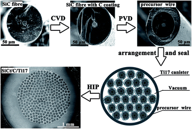
Fig. 1 illustrates the fabrication process of SiCf/C/Ti17. The reinforcement was tungsten-cored SiC monofilament with 100 μm in diameter (provided by AECC Beijing Institute of Aeronautical Materials, China) on which a ∼3 μm thick turbostratic carbon coating (C coating) was coated by single filament chemical vapour deposition (CVD). During the CVD process for C coating, the deposition temperature was 1000 °C and the reactant gas was acetylene. Then the matrix, Ti17 alloy, about 27 μm in thickness, was deposited on C-coated SiC fibres to fabricate precursor wires by matrix-coated fibre (MCF) method through physical vapour deposition (PVD) process. The deposition of precursor wires was done in a facing-target magnetron sputtering system with base pressure of approximately 4.0 × 10⁻⁴ Pa. Next, these precursor wires were putted into a Ti17 alloy canister hermetically to conduct sealing process using electron beam wielding. Subsequently, SiCf/C/Ti17 was manufactured by consolidating those packed precursor wires which have been sealed in a canister through HIP at 920 °C under an gas pressure of 120 MPa for a holding time of 2 hours, and then furnace cooled to room temperature. It could be clearly seen in Fig. 1 that the SiCf/C/Ti17 was well consolidated after HIP. The size of composite was about 2.5 mm in diameter. Finally, the SiCf/C/Ti17 was sectioned perpendicular to the axis of fibre into slices, which were thermally exposed at 450 °C/600 h, 800 °C/600 h and 1100 °C/2 h, respectively. All thermal exposures were processed on composites encapsulated in evacuated silica tubes.Characterization
The cross sectional morphologies of SiCf/C/Ti17 (slightly polished) were observed by scanning electron microscope SU8010 (SEM). The interfacial reaction products were investigated by field emission JEOL 2010F transmission electron microscope (TEM). The chemical compositions of each sub-layer in interfacial zone were examined by energy dispersive X-ray spectrometer (EDX) equipped in TEM. Specimens for TEM observation were cut from the composites normal to the fibre axis, and then were ground into 100 μm by Leica M80 grinder and were finally thinned by Leica EM RES 102 ion beam milling system to meet the requirement of TEM analysis.Results and discussion
The interfacial zone of as-processed SiCf/C/Ti17
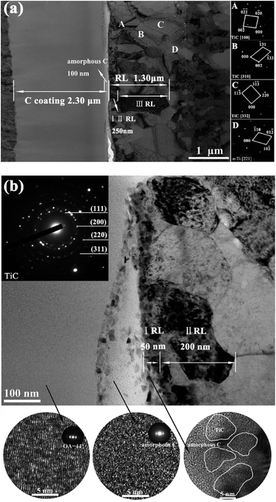
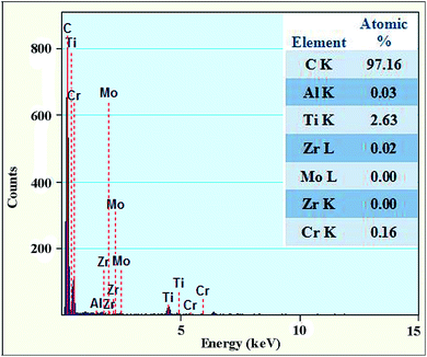
During the process of consolidating precursor wires into SiCf/C/Ti17 by HIP at 920 °C/120 MPa/2 h, chemical reaction between the outmost C coating and Ti17 matrix inevitably took place: Ti + C = TiC, ∇G = −169 kJ mol−1 at 920 °C,14 leading to the depletion of C coating and formation of interfacial reaction zones, as shown in Fig. 2. From the TEM images of interfacial zone for the as-processed SiCf/C/Ti17, it can be observed that the residual C coating is about 2.3 μm thick, comprising of a ∼2.2 μm-thick turbostratic C layer adjacent to the SiC fibre and a ∼100 nm-thick amorphous C layer close to Ti17 matrix. The high textured turbostratic C, identified by orientation angle OA = 44°, mainly consisted of (002) planes parallel to the fibre axial direction and perpendicular to the fibre radial direction as shown by the high resolution transmission electron microscope (HRTEM) image in Fig. 2(b).17–19 In contrast, trace matrix elements (∼3%) could be detected in the thin amorphous C layer, revealed by EDX in Fig. 3, meaning that the diffusion entry of metal atoms induced original turbostratic C transforming into amorphous C.20,21As identified by selected area electron diffraction (SAED) patterns, the interfacial reaction layer (RL) is just composed of different-sized TiC and its average thickness is about 1.3 μm. On the basis of TiC grains size, RL could be divided into three sub-layers, including fine-grained layer adjacent to C coating, transition layer in the middle of RL zone, and coarse-grained layer near to matrix, labelled as I RL, II RL and III RL, respectively. Higher magnification TEM image for I RL, II RL is also shown in Fig. 2(b), and it is noticed that fine TiC grains are surrounded by the amorphous C in I RL and the amorphous C disappeared in II RL. Obviously, a large difference in grain sizes occurred in I RL, II RL and III RL, exhibiting abrupt increases in grain sizes from below ∼30 nm in I RL to larger than ∼500 nm in III RL through ∼200 nm in II RL. The thickness for I RL, II RL and III RL are evaluated to be ∼50 nm, ∼200 nm and ∼1.0 μm, respectively. In addition, according to the EDX results in Table 1, I RL, II RL and III RL display C-rich, near-stoichiometric and C-deficient characters, respectively, presenting an obvious C concentration gradient along RL, which should result from the continuous outward diffusion of C atom towards Ti17 matrix during HIP.12 Consequently, continuous C diffusion towards matrix during HIP, coupled with simultaneous grain growth, yielded abrupt increases in TiC grain sizes and C concentration gradient along RL, finally formed the interfacial zone described as turbostratic C||amorphous C||fine-grained TiC||transition TiC||coarse-grained TiC.
| As-processed | 450 °C/600 h | 800 °C/600 h | 1100 °C/2 h | |||||
|---|---|---|---|---|---|---|---|---|
| C | Ti | C | Ti | C | Ti | C | Ti | |
| I RL | 58.6 | 40.3 | 57.8 | 41.0 | 50.1 | 48.5 | — | — |
| II RL | 48.6 | 49.3 | 48.1 | 49.7 | 41.2 | 57.3 | 44.4 | 53.6 |
| III RL | 45.1 | 50.6 | 43.8 | 51.8 | 35.0 | 62.1 | 36.2 | 60.2 |
The forming process of the interfacial zone could be summarized by the following two stages. In the initial stage of HIP, the amorphous C layer and the fine-grained I RL were considered as the reaction fronts triggered by the interdiffusion between C and Ti, in which diffusion entry into turbostratic C of trace metal atoms induced its amorphization, on the other hand, diffusion towards the Ti17 matrix of large amount of C atoms provided sufficient reaction atoms and high nucleation rate, evidenced by the observed nano-composited structure of nc-TiC phase embedded into an amorphous C matrix, promoting the formation of fine-grained I RL.14,22 The initial stage of HIP has been described as reaction-controlled process,23,24 during which nanocrystalline nc-boundaries provided short-circuit paths to the diffusion of amorphous C.25 During the process of C atoms passing through I RL, obvious grain growth of Ti matrix took place at zones nearby I RL simultaneously, thereby forming near-stoichiometric II RL through further reaction, which was responsible for the abrupt increment in grain size to ∼200 nm in II RL. This new production of compacted TiC II RL could be regarded as a diffusion barrier layer,26 and the further interfacial reaction would be determined by diffusion-controlled process, during which the interfacial reaction rate was governed by the diffusivity of C through the formed TiC II RL,24 since the diffusivity of C in TiC is several orders larger than Ti.27 Finally, when C diffuse through the I RL and II RL, it reacted with the grown Ti grains and produced coarse-grained TiC III RL with lager grain size about 500–1000 nm.28
The evolution of interfacial zones in SiCf/C/Ti17 activated by different thermal treatment temperature
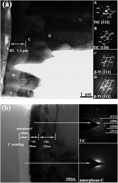
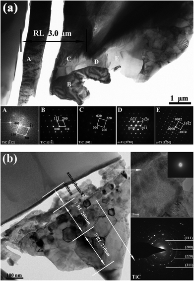
It was reported that the service temperature of Ti17 alloy applied in aerospace field is about 427 °C.16,29 Since the interfacial zone has been divided into turbostratic C||amorphous C||fine-grained TiC||transition TiC||coarse-grained TiC for as-processed SiCf/C/Ti17 sample, it is necessary to investigate its interfacial stability at this temperature for long-term reliability applications. Accordingly, the as-processed SiCf/C/Ti17 was firstly exposed at 450 °C for 600 h, and the thickness as well as microstructure of each sub-layer in interfacial zone was identified by TEM and SAED patterns, which are shown in Fig. 4, presenting same interfacial zone as the as-processed sample involving turbostratic C||amorphous C||fine-grained TiC||transition TiC||coarse-grained TiC. As identified by the lower right corner inset diffraction ring in Fig. 4(b), the amorphous C layer, stemming from the diffusion entry of trace metal atoms during HIP, maintains the same thickness of ∼100 nm as that in as-processed sample subsequently to 450 °C for 600 h exposure. At the same time, the total thickness of RL also remains unchanged at ∼1.3 μm, as confirmed by SAED, comprising of a ∼80 nm-thickness fine-grained I RL with grain size below 30 nm, a ∼170 nm-thickness transition II RL, and a ∼1.0 μm-thickness coarse-grained III RL. Additionally, no obvious grains growth took place in each sub-layer of RL. It is concluded that the interfacial zone of SiCf/C/Ti17 maintained good stability subsequently to 450 °C/600 h thermal exposure, evidenced by the almost same thickness, grain size and microstructure for each sub-layer in interfacial zone as these in the as-processed composite, suggesting that the SiCf/C/Ti17 remained interfacial inertia under this temperature and provided high reliability for long term service.In order to further investigate the evolution of interfacial zone activated by higher temperature, the as-processed composite was exposed at 800 °C for 600 h, and the TEM images and SAED patterns for corresponding interfacial products are shown in Fig. 5. Although there is still a ∼100 nm thick amorphous C layer locating between the turbostratic C layer and I RL, similar to the as-processed composite, the residual thickness of C coating decreased from ∼2.3 μm for as-processed and 450 °C/600 h thermally treated composites to ∼1.8 μm for 800 °C/600 h treated composite, supported by the SEM results displayed in Fig. 6. This meant that motived by the 800 °C high temperature, the interfacial zone could not maintain the inertia that was present at 450 °C, whereas the amorphous C layer was continuously transferred from the turbostratic C layer by means of diffusion entry of the trace metal atoms. This occurred along with the continuous C diffusion towards the matrix, the yield of static balance with the unchanged thickness of the amorphous C layer and the reduction in thickness of the turbostratic C layer as well as the increment in the RL total thickness. The RL total thickness remarkably increased up to ∼3.0 μm, still composed of different-sized TiC sub-layers, which was confirmed by SAED, suggesting that the residual C coating could effectively inhibit the direct reaction between the SiC fibre and the Ti17 matrix. Clearly, subsequently to the thermal exposure at 800 °C/600 h, a grains growth appeared in the fine-grained I RL, reaching to 50–100 nm, as compared to below 30 nm, which could be ascribed to the reduced C content in I RL, as presented in Table 1. This corresponded to a drop in amorphous C, as well as to the interface energy minimization provided by grain growth in the ultrafine grains.30 In contrast, the higher-sized TiC grains in transition II RL retained stability with an unchanged grain size. The thickness of each sub-layer for I RL, II RL and III RL in the 800 °C/600 h treated SiCf/C/Ti17 was evaluated to ∼200 nm, ∼230 nm and ∼2.6 μm, respectively, implying that the increment in thickness of III RL dominated the RL growth.
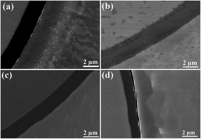 | ||
| Fig. 6 Cross-sectional SEM images of SiCf/C/Ti17 (a) as-processed composite and thermally exposed composites at (b) 450 °C/600 h, (c) 800 °C/600 h, (d) 1100 °C/2 h. | ||
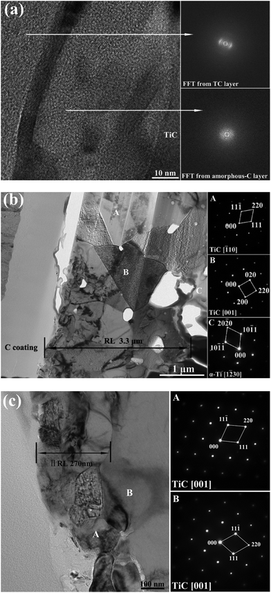
800 °C treatment has activated the interfacial reaction, but the reaction rate was very slow, still remaining ∼1.8 μm residual C coating after 600 h. The SiCf/C/Ti17 was also exposed at 1100 °C/2 h to further investigate the interfacial evolution for evaluating the possibility in high-temperature short term applications. As compared with 800 °C/600 h treated sample, it could be seen from SEM images in Fig. 6 that just 2 h treatment at 1100 °C triggered more violent interfacial reaction, remaining less residual C coating of ∼1.3 μm thickness and yielding thicker RL of ∼3.3 μm evaluated from Fig. 7. Different from the presence of ∼100 nm amorphous C layer, situated between turbostratic C layer and fine-grained I RL, in the 450 °C/600 h treated SiCf/C/Ti17, resulting from its interfacial inertia, and in the 800 °C/600 h treated SiCf/C/Ti17, coming from the static balance between amorphization rate of turbostratic C layer and diffusion rate of C atoms from amorphous C layer towards matrix, the amorphous C layer reduced to ∼35 nm thick for 1100 °C/2 h exposed composite, evidenced by Fig. 7(a). This showed that the diffusion rate of C atoms from amorphous C layer towards matrix was slightly faster than amorphization rate of turbostratic C layer under the condition of 1100 °C. Additionally, the 1100 °C/2 h treatment remarkably promoted the grains growth in the fine-grained I RL, reaching to 100–200 nm in size and following merger with the transition II RL, as presented by Fig. 7(c), suggesting the fine-grained I RL disappearance. Also, the coarse-grained III RL adjacent to the Ti17 matrix, reached up to ∼3.0 μm in thickness with 1 μm in grains size, as three times higher than ∼1.0 μm in thickness for the as-processed sample. Although 1100 °C/2 h treatment triggered violent interfacial reaction, the residual C coating could still inhibit effectively the direct reaction between SiC fibre and Ti17 matrix, supported by only TiC productions identified by the SAED patterns in Fig. 7(b) and (c). In brief, 1100 °C/2 h treatment activated further interfacial reaction and induced obvious increment in grain size and thickness of each sub-layer, resulting in interfacial zone evolved to turbostratic C||amorphous C||transition TiC||coarse-grained TiC.
As mentioned above, during the process of HIP at 920 °C, high HIP temperature activated continuous C atoms diffusion from amorphous C layer towards Ti17 matrix and simultaneous grains growth of matrix from tens of nanometres for the precursor wires fabricated by MCF method to larger than 500 nm for the compacted composites, which made interfacial reaction undergo from initially reaction-controlled to finally diffusion-controlled process, forming interfacial zone with abrupt increase in TiC grain sizes and C concentration gradient along RL for as-processed SiCf/C/Ti17, described as turbostratic C||amorphous C||fine-grained TiC||transition TiC||coarse-grained TiC. The following thermal exposure experiments including 450 °C/600 h, 800 °C/600 h and 1100 °C/2 h showed that the evolution of interfacial zones in SiCf/C/Ti17 mainly involving the variations of grain size and thickness of each sub-layer, strongly depended on the exposed temperature. The major element composition and the distributions of each sub-layer in interfacial zones for the as-processed and thermally exposed SiCf/C/Ti17 are summarized in Tables 1 and 2, respectively. The interfacial zone, nearly the same as the as-processed composite, basically maintained inertia under the condition of 450 °C/600 h. Both 800 °C/600 h and 1100 °C/2 h thermal exposures activated the further interfacial reaction, mainly yielding: (1) the residual thickness of the turbostratic C layer decreased from ∼2.3 μm for the as-processed composite to ∼1.8 μm and ∼1.3 μm subsequently to both 800 °C/600 h and 1100 °C/2 h thermal exposures, respectively; (2) the grain growth of the fine-grained I RL from below 30 nm for the as-processed composite increased to 50–100 nm for the 800 °C/600 h treated composite and finally to 100–200 nm, merging with the transition II RL for 1100 °C/2 h treated composite; (3) the total RL thickness increment from ∼1.3 for the as-processed composite increased to ∼3.0 μm and ∼3.3 μm subsequently to both 800 °C/600 h and 1100 °C/2 h thermal exposures, respectively.
| C coating/μm | Amorphous C/nm | I RL/nm | II RL/nm | III RL/μm | |
|---|---|---|---|---|---|
| As-processed | 2.3 | 100 | 50 | 200 | 1.0 |
| 450 °C/600 h | 2.3 | 100 | 80 | 170 | 1.0 |
| 800 °C/600 h | 1.8 | 100 | 200 | 230 | 2.6 |
| 1100 °C/2 h | 1.3 | 35 | — | 270 | 3.0 |
In comparison with the as-processed sample, the further depletion of the C coating and remarkable thickening of the RL induced by the 800 °C/600 h and 1100 °C/2 h thermal exposures were essentially controlled by the diffusion rate of C atoms across the formed TiC layers, since the diffusivity of C in TiC was higher by several orders of magnitude compared to the Ti diffusivity.31,32 It is known that the diffusion coefficient of C in TiC (Dc) is temperature-dependent that remarkably increases as the temperature increases. The Dc was approximately 10−14 cm2 s−1 at 450 °C,31 which was two orders of magnitude lower than at 800 °C (10−12 cm2 s−1), reaching to 10−11 cm2 s−1 at the temperature of approximately 1100 °C.33 It was reported that the interfacial reaction rate was decelerated by the presence of alloying elements, particularly the β-phase stabilized elements (as examples, the Mo, V and Cr).15 It was expected that the alloying elements would further affect the Dc, whereas the V and Cr in Ti17 might decelerate the Dc, maintaining the interfacial inertia to last at 450 °C for 600 h. The rapid increase of Dc at 800 °C increased the C coating depletion and thickened the RL subsequently to 600 h of thermal exposure. In contrast, a treatment just for 2 h at 1100 °C triggered a significantly violent interfacial reaction compared to the 800 °C/600 h exposure, suggesting that the applied temperature could essentially dominate the interfacial reaction, as quite stronger than the thermal exposure duration.13 The formation of thick RL in a short time was caused by the stronger and quicker interdiffusion of C and Ti, impelled by the high temperature.24,32
Besides the temperature-dependent diffusion coefficients controlling the C coating depletion and RL thickening, the temperature also governed the grain growth of the fine-grained I RL. Firstly, it was noted from Table 1 that both 800 °C/600 h and 1100 °C/2 h exposures transformed the C-rich TiC in the fine-grained I RL for the as-processed composite into near-stoichiometric TiC, unlocking the restriction effect of thin amorphous C in impeding the growth of TiC grains.14 On the other hand, the grain growth is driven by the reduction in the total grain boundary area and the corresponding reduction in the total grain boundary energy. At a more microscopic scale, this is accomplished when the boundaries of nearby grains move towards the corresponding centres of curvature, in order to reduce the boundary curvature and therefore the boundary energy, which can be expressed by the following equation:34
 | (1) |
![[r with combining macron]](https://www.rsc.org/images/entities/i_char_0072_0304.gif) is the average grain radius,
is the average grain radius, ![[m with combining macron]](https://www.rsc.org/images/entities/i_char_006d_0304.gif) the average grain boundary mobility,
the average grain boundary mobility, ![[small gamma, Greek, macron]](https://www.rsc.org/images/entities/i_char_e0c4.gif) gb the average grain boundary energy and
gb the average grain boundary energy and ![[small kappa, Greek, macron]](https://www.rsc.org/images/entities/i_char_e0cb.gif) is the average boundary curvature, where the grain boundary mobility is a temperature-dependent term. The grain growth mainly occurred at the fine-grained I RL from below 30 nm for the as-processed composite, to 50–100 nm for the 800 °C/600 h treated composite and finally to 100–200 nm, merging with the transition II RL for the 1100 °C/2 h treated composite. The nanoscale fine grains provided sufficient high boundary curvature, while the higher temperature activated the higher grain boundary mobility ability, contributing to the observed event.
is the average boundary curvature, where the grain boundary mobility is a temperature-dependent term. The grain growth mainly occurred at the fine-grained I RL from below 30 nm for the as-processed composite, to 50–100 nm for the 800 °C/600 h treated composite and finally to 100–200 nm, merging with the transition II RL for the 1100 °C/2 h treated composite. The nanoscale fine grains provided sufficient high boundary curvature, while the higher temperature activated the higher grain boundary mobility ability, contributing to the observed event.
In summary, the interfacial inertia in SiCf/C/Ti17 under the 450 °C/600 h thermal exposure provided high reliability for long term service under this condition. Although both 800 °C/600 h and 1100 °C/2 h thermal exposures activated a violent interfacial reaction, the residual turbostratic C coating could still effectively inhibit the chemical attack of SiC fibres by the Ti17 matrix, even at 800 °C for 600 h and 1100 °C for 2 h of thermal exposures.
Conclusions
The as-processed SiCf/C/Ti17 was consolidated with HIP at 920 °C/120 MPa/2 h, which activated the continuous C atoms diffusion from the amorphous C layer towards the Ti17 matrix and the simultaneous grain growth of the matrix, sustaining the initially reaction-controlled to the finally diffusion-controlled interfacial reaction. Simultaneously, the interfacial zone was formed with an abrupt increase in TiC grain sizes and a C concentration gradient along the RL. This was described as the turbostratic C||amorphous C||fine-grained TiC||transition TiC||coarse-grained TiC. The interfacial zone maintained inertia, identified by the observed same thickness of each sub-layer as the as-processed composite, suggesting that the SiCf/C/Ti17 could reliably serve for a long term below 450 °C. The 800 °C/600 h condition activated the diffusion of C atoms from the amorphous C layer towards the matrix and the grain growth of the fine-grained I RL, yielding the C coating depletion and the RL rapid thickening, reaching to ∼3.0 μm as three times thicker than the as-processed composite. Also, the RL thickness reached ∼3.3 μm subsequently to thermal exposure at 1100 °C for just 2 h. Moreover, the fine-grained TiC in the I RL grew into 100–200 nm in size, merging with the transition II RL, evolving to turbostratic C||amorphous C||transition TiC||coarse-grained TiC. The residual turbostratic C coating could still effectively inhibit the chemical attack of SiC fibres by the Ti17 matrix, even at 800 °C for 600 h and 1100 °C for 2 h of thermal exposures.Conflicts of interest
There are no conflicts to declare.Acknowledgements
The support from National Key R&D Program of China (2016YFA0200400), National Natural Science Foundation of China (Grant No. 51672101 and 51602122), the NSF of Jilin Province (No. 20160520010JH and 20170520120JH) China, the Aviation Science Foundation of China (No. 201430R4001), Program for JLU Science and Technology Innovative Research Team, China postdoctoral Science Foundation (Grant No. 2016M600229), is highly appreciated.Notes and references
- A. Vassel, Mater. Sci. Eng., A, 1999, 263, 305–313 CrossRef.
- J. H. Lou, Y. Q. Yang, Q. Sun, J. Li and X. Luo, Mater. Sci. Eng., A, 2011, 529, 88–93 CrossRef CAS.
- W. D. Zeng, P. W. M. Peters and Y. Tanaka, Composites, Part A, 2002, 33, 1159–1170 CrossRef.
- P. W. M. Peters and J. Hemptenmacher, Composites, Part A, 2002, 33, 1373–1379 CrossRef.
- J. M. Larsen, S. M. Russ and J. W. Jones, Metall. Mater. Trans. A, 1995, 26, 3211–3223 CrossRef.
- H. J. Dudek and K. Weber, J. Mater. Sci. Lett., 2002, 21, 1651–1654 CrossRef CAS.
- R. A. Signorelli, Proc. of the 1975 Intern. Conf. on Comp. Matls., The Metal, Soc. of the AIME, New York, NY, 1975, vol. 1, pp. 411–431 Search PubMed.
- Z. J. Ma, Y. Q. Yang, X. H. Lü, X. Luo and Y. Chen, Mater. Sci. Eng., A, 2006, 433, 343–346 CrossRef.
- D. R. Tenney, W. B. Lisagor and S. C. Dixon, J. Aircr., 1989, 26, 953–970 CrossRef.
- J. H. Li, Z. X. Guo, P. S. Grant, M. L. Jenkins, B. Derby and B. Cantor, Composites, 1994, 25, 887–890 CrossRef CAS.
- C. Jones, C. J. Kiely and S. S. Wang, J. Mater. Res., 2011, 5, 1435–1442 CrossRef.
- S. Guo, C. Hu, H. Gao, Y. Tanaka and Y. Kagawa, J. Eur. Ceram. Soc., 2015, 35, 1375–1384 CrossRef CAS.
- I. W. Hall, J. L. Lirn, Y. Lepetitcorps and K. Bilba, J. Mater. Sci., 1992, 27, 3835–3842 CrossRef CAS.
- B. Huang, M. H. Li, Y. X. Chen, X. Luo and Y. Q. Yang, Mater. Charact., 2015, 109, 206–215 CrossRef CAS.
- S. Q. Guo, Y. Kagawa, H. Saito and C. Masuda, Mater. Sci. Eng., A, 1998, 246, 25–35 CrossRef.
- T. Wang, H. Guo, L. Tan, Z. Yao, Y. Zhao and P. Liu, Mater. Sci. Eng., A, 2011, 528, 6375–6380 CrossRef CAS.
- E. López-Honorato, P. J. Meadows, R. A. Shatwell and P. Xiao, Carbon, 2010, 48, 881–890 CrossRef.
- X. J. Ning, P. Pirouz, K. P. D. Lagerlof and J. Dicarloet, J. Mater. Res., 1990, 5, 2865–2876 CrossRef CAS.
- K. L. Kendig, R. Gibala and D. B. Miracle, J. Mater. Res., 2001, 16, 3366–3377 CrossRef CAS.
- W. Zhang, Y. Q. Yang, G. M. Zhao, B. Huang, Z. Q. Feng, X. Luo, M. H. Li and J. H. Lou, Intermetallics, 2013, 33, 54–59 CrossRef CAS.
- A. A. Voevodin, M. A. Capano, S. J. P. Laube, M. S. Donley and J. S. Zabinski, Thin Solid Films, 1997, 298, 107–115 CrossRef CAS.
- M. Wu, K. Zhang, H. Huang, M. Wang, H. Li, S. Zhang and M. Wen, Carbon, 2017 DOI:10.1016/j.carbon.2017.08.065.
- Y. W. Xun, M. J. Tan and J. T. Zhou, J. Mater. Process. Technol., 2000, 102, 215–220 CrossRef.
- Z. X. Guo and B. Derby, Prog. Mater. Sci., 1995, 39, 411–495 CrossRef CAS.
- Z. Y. Xiao, Y. Q. Yang, X. Luo, B. Huang and Y. Zhou, J. Am. Ceram. Soc., 2015, 98, 1937–1941 CrossRef CAS.
- Z. Y. X. Zhiyuan, Y. Q. Y. Yanqing, Z. D. K. Zongde, O. Y. Sheng, X. L. Xian and B. H. Bin, J. Raman Spectrosc., 2015, 46, 182–188 CrossRef.
- Y. C. Fu, N. L. Shi, D. Z. Zhang and R. Yang, Mater. Sci. Eng., A, 2006, 426, 278–282 CrossRef.
- G. M. Zhao, Y. Q. Yang, W. Zhang, X. Luo, B. Huang and Y. Chen, Composites, Part B, 2013, 52, 155–163 CrossRef CAS.
- T. J. Ma, W. Y. Li, B. Zhong, Y. Zhang and J. L. Li, Sci. Technol. Weld. Joining, 2013, 17, 180–185 CrossRef.
- P. Gopalan, R. Rajaraman, B. Viswanathan, K. P. Gopinathan and S. Venkadesan, J. Nucl. Mater., 1998, 256, 229–234 CrossRef CAS.
- C. Arvieu, J. P. Manaud and J. M. Quenisset, J. Alloys Compd., 2004, 368, 116–122 CrossRef CAS.
- S. Sarian, J. Appl. Phys., 1969, 40, 3515–3520 CrossRef CAS.
- K. Koyama, Y. Hashimoto and S.-i. Omori, J. Appl. Phys., 1975, 16, 211–217 CAS.
- C. V. Thompson, Annu. Rev. Mater. Res., 2000, 16, 159–190 CrossRef.
| This journal is © The Royal Society of Chemistry 2017 |

