 Open Access Article
Creative Commons Attribution 3.0 Unported Licence
Novel nanofiber yarns synchronously endued with tri-functional performance of superparamagnetism, electrical conductivity and enhanced fluorescence prepared by conjugate electrospinning
Libing Fan,
Qianli Ma,
Jiao Tian,
Dan Li,
Xue Xi,
Xiangting Dong *,
Wensheng Yu,
Jinxian Wang
 and
Guixia Liu
Key Laboratory of Applied Chemistry and Nanotechnology at Universities of Jilin Province, Changchun University of Science and Technology, Changchun 130022, China. E-mail: dongxiangting888@163.com; Fax: +86-431-85383815; Tel: +86-431-85582575
First published on 17th October 2017
Abstract
Novel one-dimensional [Fe3O4/PANI/PAN]//[Eu(BA)3phen/PAN] (PANI = polyaniline, PAN = polyacrylonitrile, BA = benzoic acid, and phen = 1,10-phenanthrolin) heterogeneous nanofiber yarns synchronously endued with excellent tri-functionality of fluorescence, superparamagnetism and electrical conductivity were successfully fabricated for the first time using conjugate electrospinning. The heterogeneous nanofiber yarns are composed of [Fe3O4/PANI/PAN] electrical–superparamagnetic nanofibers and [Eu(BA)3phen/PAN] fluorescent nanofibers, realizing effectively the isolation of dark-colored Fe3O4 nanoparticles (NPs) and PANI from Eu(BA)3phen complexes, and thus enhanced fluorescence intensity is acquired. The morphologies and properties of the samples were studied in detail using X-ray diffraction, scanning electron microscopy, energy-dispersive spectrometry, four-probe testing, a vibrating sample magnetometer and an F-7000 fluorescence spectrophotometer. The results reveal that the prepared heterogeneous nanofiber yarns have a large aspect ratio and uniform diameter, and that the nanofibers in the yarns demonstrate high orientation. It is found that the superparamagnetism and electrical conductivity of the heterogeneous nanofiber yarns can be respectively adjusted by modulating the amounts of Fe3O4 NPs and PANI in the yarns, and the highest electrical conductivity reaches up to the order of 10−3 S cm−1. More importantly, the fluorescence intensity of the heterogeneous nanofiber yarns is much stronger than that of the counterpart [Fe3O4/PANI/Eu(BA)3phen/PAN] homogeneous nanofiber yarns with the same compositions and contents owing to the fact that the Fe3O4 NPs and PANI were not directly mixed with the Eu(BA)3phen complexes. Furthermore, the design concept and preparation method provide an effective route for manufacturing other multi-functional nanofiber yarns.
Introduction
Nanofibers have been widely applied in the fields of the national defensive industry, transparent filters, optical devices, biomaterials, etc. owing to their large surface area (higher than that of ordinary microfibers), high aspect ratio (length to diameter ratio) and the ability to penetrate other substances.1–4 Nevertheless, most nanofibers are collected in the form of random nano-weaves with poor alignment.5,6 Randomly oriented fibrous structures limit the application of nanofibers in certain areas, such as sensors, cell directed migration and growth in which orientation of the nanofibers is strictly demanded.7–9 Therefore, some researchers have shifted their focus onto preparing oriented nanofiber bundles or yarns in order to enhance the actual usage of the nanofibers for innovative applications.10 Up to now, several studies on the preparation and application of nanofiber yarns have been reported. Wu, et al.11 fabricated an aligned conductive nanofiber yarn network within a hydrogel shell using an enhanced wet–dry electrospinning method to construct a 3D hybrid scaffold, and illustrated the great potential application in engineering anisotropic 3D cardiac scaffolds. Wu, et al.7 manufactured uniaxially aligned nanofiber yarns (UANYs) successfully by using a novel electrospinning system, and the UANYs possessed high cell survivability and displayed the ability to improve the cell adhesion and proliferation. Wang, et al.12 prepared poly(caprolactone) (PCL)/silk fibroin (SF)/polyaniline (PANI) aligned nanofiber yarns via a developed dry–wet electrospinning method. The aligned nanofiber yarns have good biocompatibility and the ability to induce cellular alignment, elongation and differentiation. Xie, et al.13 demonstrated that a carbon nanofiber precursor can be prepared by electrospinning PAN into nanofiber yarns for the first time. The yarns show outstanding drawing performance, and can be drawn uniformly up to 6 times their original length without breaking.With the development of nanotechnology, the demand for nanomaterials has been increased dramatically.14,15 Single functional nanomaterials are gradually unable to meet the needs of practical applications, therefore, many researchers from different countries and regions have focused their efforts on turning single functional nanomaterials into multifunctional nanomaterials in recent years.16 Considerable research effort has been devoted to nanomaterials possessing magnetic–fluorescence bifunctionality, which benefits many technical fields such as biological imaging,17,18 drug delivery19,20 and magnetic resonance.21 Thus, more and more researchers pay attention to fluorescent–electrical–magnetic bi- or tri-functional nanomaterials. Generally, rare earth (RE) complexes have excellent fluorescence properties due to the f–f electron transition and thus have applications in sensors, laser materials, solar energy conversion materials, etc.22,23 Fe3O4 NPs as magnetic materials show great potential for various fields such as magnetic-controlled switches, electronics and biological processes because of their unique superparamagnetism, good biocompatibility and high permeability.24,25 PANI, as a very popular conductive polymer, has been widely applied in supercapacitor electrodes, electromagnetic shielding materials, and gas sensors on account of the advantages of easy synthesis, low cost, adjustable performance, good environmental stability and tunable high conductivity.26–28 There is no doubt that the fluorescence intensities of RE complexes will greatly abate if Fe3O4 NPs, Fe2O3, PANI or any other dark-colored materials are directly mixed with the RE complexes for preparing multifunctional nanomaterials.29–31 In order to get strong fluorescence properties and to overcome the above drawback, the dark-colored materials must be effectively separated from the white-colored RE complexes. So far, some types of fluorescent–electrical–magnetic trifunctional nanomaterials have been reported, such as a [Eu(TTA)3(TPPO)2/polyvinyl pyrrolidone (PVP)]/[PANI/Fe3O4/(PAN)] nanofibrous membrane,32, [Tb(BA)3phen/Fe3O4/PANI/PVP] hollow nanofibers33 and [polyfluorene (PF–Na)/Fe3O4/polyvinyl alcohol (PVA)] composite nanofibers,34 which have potential applications in cell separation, magnetic resonance, biological imaging, drug targeting, etc.
Electrospinning is a relatively straightforward and efficient method for fabricating continuous nanofibers from polymer solutions or melts, and has become a common method used by many researchers in recent years.35–41 PAN is one of the most important highly polymeric materials in electrospinning owing to its low price, good thermal and chemical stability, antioxidation and high mechanical properties, as well as the prepared nanofibers having stable physical and chemical properties,42–44 and thus it was selected for this work. Herein, we designed and constructed novel [Fe3O4/PANI/PAN]//[Eu(BA)3phen/PAN] fluorescent–electrical–superparamagnetic trifunctional nanofiber yarns by using a conjugate electrospinning method. The [Fe3O4/PANI/PAN]//[Eu(BA)3phen/PAN] nanofiber yarns were made up of two different nanofibers, namely [Fe3O4/PANI/PAN] nanofibers and [Eu(BA)3phen/PAN] nanofibers. We have named this kind of nanofiber yarn as a heterogeneous nanofiber yarn. In order to highlight the excellent performance of heterogeneous nanofiber yarns, [Fe3O4/PANI/Eu(BA)3phen/PAN] nanofiber yarns were also prepared via the same method, which were named as homogeneous nanofiber yarns. The homogeneous nanofiber yarns consisted of only one kind of nanofiber, namely [Fe3O4/PANI/Eu(BA)3phen/PAN] nanofibers. Finally, the prepared nanofiber yarns were systematically characterized using different modern determination techniques, and some valuable outcomes were gained. To our knowledge, there are no reports on fabricating nanofiber yarns which possess the tri-functionality of fluorescence, electrical conductivity and superparamagnetism. On account of their multi-functionality, this novel type of heterogeneous nanofiber yarn will have potential applications in nano-devices, drug targeting and imaging, electromagnetic interference shielding, etc. More importantly, the synthetic strategy applied in this work can be extended to prepare nanofiber yarns with other functions.
Experimental section
Chemical reagents
Eu2O3 (99.99%), concentrated nitric acid (HNO3) (A.R.), 1,10-phenanthrolin (phen) (A.R.), benzoic acid (BA) (A.R.), FeSO4·7H2O (A.R.), FeCl3·6H2O (A.R.), polyethylene glycol (PEG, Mw ≈ 20![[thin space (1/6-em)]](https://www.rsc.org/images/entities/char_2009.gif) 000) (A.R.), NH4NO3 (A.R.), ammonia (NH3·H2O) (A.R.), oleic acid (OA) (A.R.), aniline (ANI) (A.R.), (1S)-(+)-camphor-10 sulfonic acid (CSA) (A.R.), ammonium persulfate (APS) (A.R.), polyacrylonitrile (PAN) (A.R.), N,N-dimethylformamide (DMF) (A.R.), and anhydrous ethanol (A.R.) were all bought from Aladdin Chemistry Co., Ltd.
000) (A.R.), NH4NO3 (A.R.), ammonia (NH3·H2O) (A.R.), oleic acid (OA) (A.R.), aniline (ANI) (A.R.), (1S)-(+)-camphor-10 sulfonic acid (CSA) (A.R.), ammonium persulfate (APS) (A.R.), polyacrylonitrile (PAN) (A.R.), N,N-dimethylformamide (DMF) (A.R.), and anhydrous ethanol (A.R.) were all bought from Aladdin Chemistry Co., Ltd.
Syntheses of OA-modified Fe3O4 NPs
In this work, we used a co-precipitation method to prepare Fe3O4 NPs with particle sizes of 8–10 nm. The detailed preparation procedures are described in the literature.45Syntheses of europium complexes
Eu(BA)3phen complexes were prepared according to the method described in the literature.46Fabrication of the [Fe3O4/PANI/PAN]//[Eu(BA)3phen/PAN] fluorescent–electrical–superparamagnetic trifunctional heterogeneous nanofiber yarns by conjugate electrospinning
An electrospinning solution A for fabricating [Eu(BA)3phen/PAN] nanofibers was prepared as follows: Eu(BA)3phen complexes were added into DMF (5.0000 g) and then PAN (0.5000 g) was introduced under magnetic stirring at 60 °C for 3 h to form a uniform solution. The actual components of spinning solution A are shown in Table 1. An electrospinning solution B for fabricating [Fe3O4/PANI/PAN] nanofibers was prepared as follows: Fe3O4 NPs were dispersed into DMF (7.5000 g) under ultrasonic dispersion for 20 min and then PAN (0.9000 g) was added into the above suspension with mechanical agitation at 60 °C for 3 h. Then, ANI and CSA were dispersed into the suspension at room temperature for 3 h, which was named as solution 1. APS was dissolved into the DMF (1.5000 g) as an oxidant and stirred at room temperature for 3 h, which was denoted as solution 2. The solutions 1 and 2 were placed in a refrigerator at 0 °C for 1 h. Then, solution 1 was poured into solution 2 to mix together, and the mixture was mechanically agitated in an ice-water bath for 2–3 h. After that, the reaction system was maintained for one day at 0 °C to obtain solution B (Table 2).| Solution A | Eu(BA)3phen![[thin space (1/6-em)]](https://www.rsc.org/images/entities/char_2009.gif) : :![[thin space (1/6-em)]](https://www.rsc.org/images/entities/char_2009.gif) PAN (wt%) PAN (wt%) |
Eu(BA)3phen (g) | PAN (g) | DMF (g) |
|---|---|---|---|---|
| SA1 | 5 | 0.0250 | 0.5000 | 5.0000 |
| SA2 | 10 | 0.0500 | 0.5000 | 5.0000 |
| SA3 | 15 | 0.0750 | 0.5000 | 5.0000 |
| SA4 | 20 | 0.1000 | 0.5000 | 5.0000 |
| SA5 | 25 | 0.1250 | 0.5000 | 5.0000 |
| Solution B | Fe3O4![[thin space (1/6-em)]](https://www.rsc.org/images/entities/char_2009.gif) : :![[thin space (1/6-em)]](https://www.rsc.org/images/entities/char_2009.gif) PAN (mass ratio) PAN (mass ratio) |
PANI![[thin space (1/6-em)]](https://www.rsc.org/images/entities/char_2009.gif) : :![[thin space (1/6-em)]](https://www.rsc.org/images/entities/char_2009.gif) PAN (wt%) PAN (wt%) |
Fe3O4 (g) | PANI (g) | CSA (g) | APS (g) | DMF (g) | PAN (g) |
|---|---|---|---|---|---|---|---|---|
| SB1 | 1![[thin space (1/6-em)]](https://www.rsc.org/images/entities/char_2009.gif) : :![[thin space (1/6-em)]](https://www.rsc.org/images/entities/char_2009.gif) 1 1 |
40 | 0.9000 | 0.3600 | 0.4489 | 0.8834 | 9.0000 | 0.9000 |
| SB2 | 1![[thin space (1/6-em)]](https://www.rsc.org/images/entities/char_2009.gif) : :![[thin space (1/6-em)]](https://www.rsc.org/images/entities/char_2009.gif) 1 1 |
50 | 0.9000 | 0.4500 | 0.5620 | 1.1036 | 9.0000 | 0.9000 |
| SB3 | 1![[thin space (1/6-em)]](https://www.rsc.org/images/entities/char_2009.gif) : :![[thin space (1/6-em)]](https://www.rsc.org/images/entities/char_2009.gif) 1 1 |
60 | 0.9000 | 0.5400 | 0.6740 | 1.3233 | 9.0000 | 0.9000 |
| SB4 | 1![[thin space (1/6-em)]](https://www.rsc.org/images/entities/char_2009.gif) : :![[thin space (1/6-em)]](https://www.rsc.org/images/entities/char_2009.gif) 1 1 |
70 | 0.9000 | 0.6300 | 0.7862 | 1.5439 | 9.0000 | 0.9000 |
| SB5 | 0.5![[thin space (1/6-em)]](https://www.rsc.org/images/entities/char_2009.gif) : :![[thin space (1/6-em)]](https://www.rsc.org/images/entities/char_2009.gif) 1 1 |
60 | 0.4500 | 0.5400 | 0.6740 | 1.3233 | 9.0000 | 0.9000 |
| SB6 | 2![[thin space (1/6-em)]](https://www.rsc.org/images/entities/char_2009.gif) : :![[thin space (1/6-em)]](https://www.rsc.org/images/entities/char_2009.gif) 1 1 |
60 | 1.8000 | 0.5400 | 0.6740 | 1.3233 | 9.0000 | 0.9000 |
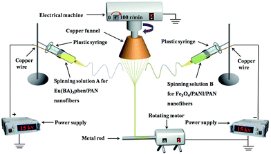
The electrospinning system for fabricating the nanofiber yarns is shown in Fig. 1. Solutions A and B were loaded into two plastic syringes equipped with spinnerets, which were respectively connected to the positive and negative high-voltage direct current (DC) power supplies using copper wires. The two syringes were fixed symmetrically on both sides of the grounded copper funnel. An applied voltage was tuned to about ±15 kV, and the distance from the top of the spinneret to the side of the copper funnel was 10 cm. The collecting device was placed below the copper funnel, and consisted of a speed-adjustable motor and a metal rod. The distance between the lower edge of the funnel and the collecting device was 18 cm. PAN-based continuous nanofiber yarns were prepared at a room temperature of 20 ± 5 °C and the relative humidity was 20 ± 5%.
After the power supplies were turned on, an electrostatic field was formed between the positive and negative spinnerets. The spinning solutions A and B were ejected under the action of the electrostatic field, and then nanofibers were formed from pulling under the action of the electrostatic attraction and solidifying as the solvent was volatilized. The nanofibers produced from solutions A and B were bonded and charge neutralized after they encountered one another. A piece of grounded metal wire was placed near the central area under the copper funnel, and then a stable conical assemblage consisting of two kinds of nanofibers was gradually formed between the funnel edges and the endpoint of the metal wire. The twisted nanofiber yarns were successfully prepared by rotating the funnel and the yarns were drawn to the collecting device by the guidance of the metal wire. The revolving speed of the copper funnel and the collection rate were 100 rpm and 0.03 m s−1, respectively. For convenience of comparison, the volume of spinning solution in each syringe was fixed to 2 mL during every electrospinning process, and the experiment was not stopped until the solutions were synchronously and completely consumed.
Fabrication of the [Fe3O4/PANI/Eu(BA)3phen/PAN] fluorescent–electrical–superparamagnetic trifunctional homogeneous nanofiber yarns by conjugate electrospinning
To highlight the advantages of the heterogeneous nanofiber yarns, [Fe3O4/PANI/Eu(BA)3phen/PAN] fluorescent–electrical–superparamagnetic trifunctional homogeneous nanofiber yarns were also fabricated as a contrast sample. The preparation method was as follows: spinning solutions A3 and B3 were mixed together at a volume ratio of 1![[thin space (1/6-em)]](https://www.rsc.org/images/entities/char_2009.gif) :
:![[thin space (1/6-em)]](https://www.rsc.org/images/entities/char_2009.gif) 1 in a conical flask under mechanical agitation for 2 h until the mixture was evenly mixed, and then electrospinning was executed under the same conditions as depicted in the above process.
1 in a conical flask under mechanical agitation for 2 h until the mixture was evenly mixed, and then electrospinning was executed under the same conditions as depicted in the above process.
Characterization methods
The as-prepared Fe3O4 NPs, [Fe3O4/PANI/PAN]//[Eu(BA)3phen/PAN] heterogeneous nanofiber yarns and [Fe3O4/PANI/Eu(BA)3phen/PAN] homogeneous nanofiber yarns were analyzed using X-ray power diffraction (XRD). The morphology of the nanofiber yarns was observed using a scanning electron microscope (SEM), which was equipped with an energy-dispersive X-ray spectrometer (EDS). A four-probe tester (RTS-4) was used to detect the electrical conduction properties of the samples. The fluorescence properties were studied using an F-7000 fluorescence spectrophotometer made by Hitachi. Then, the superparamagnetic performance of the Fe3O4 NPs and nanofiber yarns was investigated using a vibrating sample magnetometer (VSM), purchased from Quantum Design Inc., of MPMS SQUID XL type. All of the tests were conducted at room temperature.Results and discussion
Phase analyses
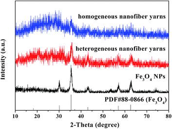
Fig. 2 shows the XRD results of the as-prepared Fe3O4 NPs, [Fe3O4/PANI/PAN]//[Eu(BA)3phen/PAN] heterogeneous nanofiber yarns (fabricated from SB3//SA3) and [Fe3O4/PANI/Eu(BA)3phen/PAN] homogeneous nanofiber yarns. Compared with the PDF standard card of Fe3O4 (PDF#88-0866), the XRD pattern of the as-prepared Fe3O4 NPs corresponds with a cubic structure, and there are no characteristic peaks of other impurities such as ferric oxide (Fe2O3) and basic ferrous oxide (FeO(OH)). The diffraction peaks of the Fe3O4 NPs are found in the [Fe3O4/PANI/PAN]//[Eu(BA)3phen/PAN] heterogeneous nanofiber yarns and [Fe3O4/PANI/Eu(BA)3phen/PAN] homogeneous nanofiber yarns, which means that the Fe3O4 NPs have been introduced into the two kinds of nanofiber yarn successfully. A wide diffraction peak between 15° and 25° in the yarns manifests the presence of amorphous PANI, Eu(BA)3phen complexes and PAN.Morphology and structure
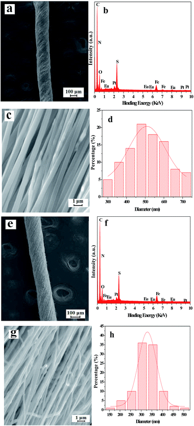
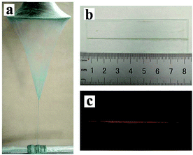
The SEM images, EDS spectra and diameter distribution histograms of nanofibers revealed in Fig. 3 demonstrate the detailed structure, element compositions and the diameter of the nanofibers in the [Fe3O4/PANI/PAN]//[Eu(BA)3phen/PAN] heterogeneous nanofiber yarns and [Fe3O4/PANI/Eu(BA)3phen/PAN] homogeneous nanofiber yarns. As revealed in Fig. 3a and e, the obvious and twisted structure of the heterogeneous nanofiber yarns and homogeneous nanofiber yarns can be clearly seen from the SEM images at low magnification, the nanofibers in the yarns are tightly arranged together in a certain direction. The corresponding EDS spectra shown in Fig. 3b and f reveal that the heterogeneous nanofiber yarns and homogeneous nanofiber yarns are comprised of the elements C, N, O, Fe, Eu, Pt and S. The peaks for Pt in the spectra are from the conductive film coated on the surface of the samples for SEM observation. The nanofibers in the yarns exhibit high degrees of alignment at high magnification, as indicated in Fig. 3c and g. As seen from Fig. 3c, some aggregations of Fe3O4 NPs can be seen on the surface of some parts of the nanofibers, and on the contrary the other nanofibers have smooth surfaces, which can be attributed to the fact that the Fe3O4 NPs are only distributed in the [Fe3O4/PANI/PAN] nanofibers but not in the [Eu(BA)3phen/PAN] nanofibers in the heterogeneous nanofiber yarns. As for the homogeneous nanofiber yarns, the Fe3O4 NPs are dispersed in every single [Fe3O4/PANI/Eu(BA)3phen/PAN] nanofiber, as revealed in Fig. 3g. Fig. 3d and h demonstrate the histograms of the diameter distribution of nanofibers in the heterogeneous nanofiber yarns and homogeneous nanofiber yarns, respectively. The average diameters of the heterogeneous nanofiber yarns and their internal nanofibers are 201 μm and 508 ± 8 nm, and the mean diameters of the homogeneous nanofiber yarns and their internal nanofibers are 148 μm and 329 ± 2 nm, respectively.Fig. 4a shows a digital photo of the conical nanofiber assemblage and the [Fe3O4/PANI/PAN]//[Eu(BA)3phen/PAN] heterogeneous nanofiber yarns coiled around the metal rod. It can be seen from Fig. 4b that the heterogeneous nanofiber yarns have a large aspect ratio, and Fig. 4c displays the red light emitted from the heterogeneous nanofiber yarns under 278 nm UV illumination in darkness, which corresponds to Fig. 4b.
Fluorescence performance
A series of [Eu(BA)3phen/PAN] nanofibers (fabricated by spinning solutions A1–5) were prepared using a traditional single-spinneret electrospinning method to obtain the optimum mass percentage of Eu(BA)3phen complexes to PAN in this work, and the mass percentages of Eu(BA)3phen complexes to PAN were 5%, 10%, 15%, 20% and 25%, respectively. The left side of Fig. 5 exhibits the excitation spectra of the [Eu(BA)3phen/PAN] nanofibers at a monitoring wavelength of 616 nm. A wide excitation band range from 200 to 400 nm is observed in all samples. The peak at 278 nm ascribed to the π → π* electronic transition of ligands can be identified. As illustrated in the emission spectra on the right side of Fig. 5, under 278 nm excitation the strong characteristic peaks of Eu3+ appear at 580, 593, and 616 nm, which are attributed to the 5D0 → 7F0, 5D0 → 7F1, and 5D0 → 7F2 energy level transitions, and the 5D0 → 7F2 hypersensitive transition at 616 nm (red light) is the primary emission peak. As revealed in Fig. 5, with the addition of more Eu(BA)3phen complexes, the fluorescence intensity of the nanofibers increases at first and then decreases. When the fluorescence intensity reaches the maximum value, the percentage of Eu(BA)3phen complexes to PAN is 15%. However, as the content of Eu(BA)3phen complexes continues to increase, the excess Eu(BA)3phen complexes will be agglomerated and then excitonic transitions will lead to much stronger nonradiative transitions among the Eu3+ ions. Therefore, the fluorescence intensity of the [Eu(BA)3phen/PAN] nanofibers is weakened. So, the content of Eu(BA)3phen complexes to PAN was fixed at 15% to prepare fluorescent–electrical–magnetic trifunctional nanofiber yarns in this study.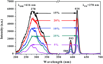 | ||
| Fig. 5 Excitation spectra (left) and emission spectra (right) of [Eu(BA)3phen/PAN] nanofibers doped with different amounts of Eu(BA)3phen complexes to PAN. | ||
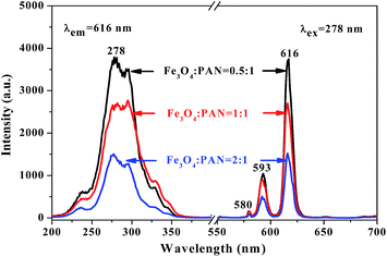
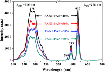
Meanwhile, [Fe3O4/PANI/PAN]//[Eu(BA)3phen/PAN] heterogeneous nanofiber yarns containing different amounts of Fe3O4 NPs and PANI were also fabricated to study the effect of different amounts of Fe3O4 NPs (fabricated from SB3//SA3, SB5//SA3 and SB6//SA3, the excitation and emission spectra are illustrated in Fig. 6) and PANI (fabricated from SB1//SA3, SB2//SA3, SB3//SA3 and SB4//SA3, the excitation and emission spectra are given in Fig. 8) on the fluorescence properties. It can be seen from Fig. 6 and 8 that the excitation and emission intensities of the heterogeneous nanofiber yarns decrease gradually with the addition of more Fe3O4 NPs and PANI. This phenomenon may be caused by light absorption by the dark-colored Fe3O4 NPs and PANI. In order to explain the effect of different amounts of Fe3O4 NPs and PANI on the fluorescence properties of the heterogeneous nanofiber yarns more clearly and intuitively, schematic diagrams of the exciting light and emitting light in heterogeneous nanofiber yarns are demonstrated in Fig. 7 and Fig. 9. It is already known that absorption by Fe3O4 NPs in ultraviolet light (where the wavelength is less than 400 nm) is much easier than in visible light (where the wavelength ranges from 400 to 760 nm), and that PANI strongly absorbs light in the region of 400–760 nm.47 Thus, Fe3O4 NPs and PANI can absorb the excitation light (281 nm) and emission light (580, 593 and 616 nm) of the heterogeneous nanofiber yarns. Furthermore, the more Fe3O4 NPs and PANI introduced into the yarns, the stronger the light absorption by the Fe3O4 NPs and PANI is, and the darker the color of the samples and the weaker the emitting light from the samples are, which can also be seen in Fig. 7 and 9.
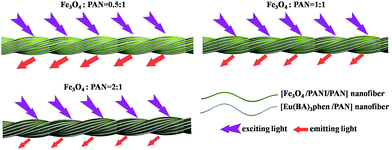 | ||
| Fig. 7 Schematic diagrams of the excitation light and emission light in heterogeneous nanofiber yarns containing different mass ratios of Fe3O4 NPs. | ||
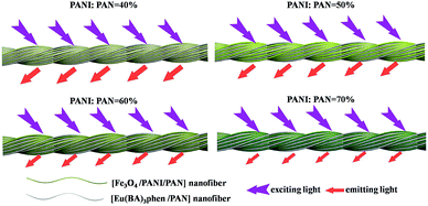 | ||
| Fig. 9 Schematic diagrams of the excitation light and emission light in heterogeneous nanofibers yarns containing different mass percentages of PANI. | ||
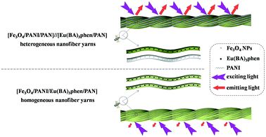
Another interesting finding is that the fluorescence property of [Fe3O4/PANI/PAN]//[Eu(BA)3phen/PAN] heterogeneous nanofiber yarns is much stronger (about 23 times) than that of [Fe3O4/PANI/Eu(BA)3phen/PAN] homogeneous nanofiber yarns under the same compositions and content, as revealed in Fig. 10. The schematic diagrams of [Fe3O4/PANI/PAN]//[Eu(BA)3phen/PAN] heterogeneous nanofiber yarns and [Fe3O4/PANI/Eu(BA)3phen/PAN] homogeneous nanofiber yarns in Fig. 11 exhibit the detailed structure of the yarns. As illustrated in the upper part of Fig. 11, heterogeneous nanofiber yarns are made up of two different nanofibers, namely the light-colored [Eu(BA)3phen/PAN] fluorescent nanofibers and dark-colored [Fe3O4/PANI/PAN] electrical–superparamagnetic nanofibers. This special structure helps to isolate the Eu(BA)3phen complexes from the Fe3O4 NPs and PANI effectively so that the excitation light and emission light in the [Eu(BA)3phen/PAN] nanofibers will be hardly affected by the dark-colored Fe3O4 NPs and PANI. The homogeneous nanofiber yarns, as demonstrated in the lower part of Fig. 11, only contain one kind of composite nanofiber. Eu(BA)3phen complexes, Fe3O4 NPs and PANI are randomly dispersed in the [Fe3O4/PANI/Eu(BA)3phen/PAN] nanofibers in the homogeneous nanofiber yarns. Hence, the excitation light must pass through many Fe3O4 NPs and PANI to approach and excite the Eu(BA)3phen complexes, as such part of the excitation light is absorbed by Fe3O4 NPs and PANI in the process, so the excitation light is weakened to a great extent before reaching the Eu(BA)3phen complexes. Likewise, the emission light emitted by the Eu(BA)3phen complexes also must pass through the Fe3O4 NPs and PANI, and is absorbed by them. As a result, both the excitation light and emission light are severely weakened. According to the above analysis, heterogeneous nanofiber yarns possess superior fluorescence performance compared to the homogeneous nanofiber yarns.
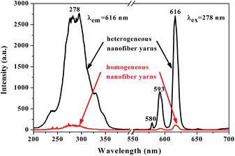 | ||
| Fig. 10 Excitation spectra (left) and emission spectra (right) of [Fe3O4/PANI/PAN]//[Eu(BA)3phen/PAN] heterogeneous nanofiber yarns and [Fe3O4/PANI/Eu(BA)3phen/PAN] homogeneous nanofiber yarns. | ||
Electrical conductivity analyses
In order to study the electrical properties of [Fe3O4/PANI/PAN]//[Eu(BA)3phen/PAN] heterogeneous nanofiber yarns and [Fe3O4/PANI/Eu(BA)3phen/PAN] homogeneous nanofiber yarns, a series of nanofiber yarns with lengths of 2.0 cm were prepared. All samples were tested three times and the average values were used as final results, the testing results are summarized in Table 3. As can be seen from Table 3, the average conductivity values of the heterogeneous nanofiber yarns increase greatly from 3.65 × 10⁻⁴ to 4.97 × 10⁻³ S cm−1 when the mass percentages of PANI to PAN are changed from 40% to 70% under the condition that the mass percentage of Eu(BA)3phen to PAN and mass ratio of Fe3O4 NPs to PAN are set to 15% and 1![[thin space (1/6-em)]](https://www.rsc.org/images/entities/char_2009.gif) :
:![[thin space (1/6-em)]](https://www.rsc.org/images/entities/char_2009.gif) 1, respectively. This result can be explained by the fact that the charge transport ability provided by the connected network of PANI is improved by adding more PANI. It also means that the electrical conductivity properties of the heterogeneous nanofiber yarns can be adjusted by changing the content of PANI. In addition, to investigate the influence of Fe3O4 NPs on the electrical conductivity, the conductivity values of the heterogeneous nanofiber yarns with different quantities of Fe3O4 NPs are also measured when the other parameters are fixed (the mass percentages of Eu(BA)3phen to PAN and PANI to PAN were set as 15% and 60%, respectively). The results in Table 3 indicate that the presence of Fe3O4 NPs has little effect on the electrical conductivity of the samples. The conductivity of the heterogeneous nanofiber yarns (SB3//SA3) is slightly higher than that of the counterpart homogeneous nanofiber yarns for the reason that the insulative Eu(BA)3phen complexes are dispersed in all of the homogeneous nanofiber yarns, which hinders the formation of the continuous conductive network to a certain extent.
1, respectively. This result can be explained by the fact that the charge transport ability provided by the connected network of PANI is improved by adding more PANI. It also means that the electrical conductivity properties of the heterogeneous nanofiber yarns can be adjusted by changing the content of PANI. In addition, to investigate the influence of Fe3O4 NPs on the electrical conductivity, the conductivity values of the heterogeneous nanofiber yarns with different quantities of Fe3O4 NPs are also measured when the other parameters are fixed (the mass percentages of Eu(BA)3phen to PAN and PANI to PAN were set as 15% and 60%, respectively). The results in Table 3 indicate that the presence of Fe3O4 NPs has little effect on the electrical conductivity of the samples. The conductivity of the heterogeneous nanofiber yarns (SB3//SA3) is slightly higher than that of the counterpart homogeneous nanofiber yarns for the reason that the insulative Eu(BA)3phen complexes are dispersed in all of the homogeneous nanofiber yarns, which hinders the formation of the continuous conductive network to a certain extent.
| Samples | Variables | Conductivity (S cm−1) | |
|---|---|---|---|
| Measurement values | Average values | ||
| SB1//SA3 | Fe3O4![[thin space (1/6-em)]](https://www.rsc.org/images/entities/char_2009.gif) : :![[thin space (1/6-em)]](https://www.rsc.org/images/entities/char_2009.gif) PAN = 1 PAN = 1![[thin space (1/6-em)]](https://www.rsc.org/images/entities/char_2009.gif) : :![[thin space (1/6-em)]](https://www.rsc.org/images/entities/char_2009.gif) 1 PANI 1 PANI![[thin space (1/6-em)]](https://www.rsc.org/images/entities/char_2009.gif) : :![[thin space (1/6-em)]](https://www.rsc.org/images/entities/char_2009.gif) PAN = 40% PAN = 40% |
2.65 × 10⁻⁴ | 3.65 × 10⁻⁴ |
| 4.60 × 10⁻⁴ | |||
| 3.71 × 10⁻⁴ | |||
| 9.09 × 10⁻⁴ | |||
| SB2//SA3 | Fe3O4![[thin space (1/6-em)]](https://www.rsc.org/images/entities/char_2009.gif) : :![[thin space (1/6-em)]](https://www.rsc.org/images/entities/char_2009.gif) PAN = 1 PAN = 1![[thin space (1/6-em)]](https://www.rsc.org/images/entities/char_2009.gif) : :![[thin space (1/6-em)]](https://www.rsc.org/images/entities/char_2009.gif) 1 PANI 1 PANI![[thin space (1/6-em)]](https://www.rsc.org/images/entities/char_2009.gif) : :![[thin space (1/6-em)]](https://www.rsc.org/images/entities/char_2009.gif) PAN = 50% PAN = 50% |
7.31 × 10⁻⁴ | 8.17 × 10⁻⁴ |
| 8.10 × 10⁻⁴ | |||
| 1.29 × 10⁻³ | |||
| SB3//SA3 | Fe3O4![[thin space (1/6-em)]](https://www.rsc.org/images/entities/char_2009.gif) : :![[thin space (1/6-em)]](https://www.rsc.org/images/entities/char_2009.gif) PAN = 1 PAN = 1![[thin space (1/6-em)]](https://www.rsc.org/images/entities/char_2009.gif) : :![[thin space (1/6-em)]](https://www.rsc.org/images/entities/char_2009.gif) 1 PANI 1 PANI![[thin space (1/6-em)]](https://www.rsc.org/images/entities/char_2009.gif) : :![[thin space (1/6-em)]](https://www.rsc.org/images/entities/char_2009.gif) PAN = 60% PAN = 60% |
1.81 × 10⁻³ | 1.50 × 10⁻³ |
| 1.40 × 10⁻³ | |||
| 4.44 × 10⁻³ | |||
| SB4//SA3 | Fe3O4![[thin space (1/6-em)]](https://www.rsc.org/images/entities/char_2009.gif) : :![[thin space (1/6-em)]](https://www.rsc.org/images/entities/char_2009.gif) PAN = 1 PAN = 1![[thin space (1/6-em)]](https://www.rsc.org/images/entities/char_2009.gif) : :![[thin space (1/6-em)]](https://www.rsc.org/images/entities/char_2009.gif) 1 PANI 1 PANI![[thin space (1/6-em)]](https://www.rsc.org/images/entities/char_2009.gif) : :![[thin space (1/6-em)]](https://www.rsc.org/images/entities/char_2009.gif) PAN = 70% PAN = 70% |
6.29 × 10⁻³ | 4.97 × 10⁻³ |
| 4.18 × 10⁻³ | |||
| 2.14 × 10⁻³ | |||
| SB5//SA3 | Fe3O4![[thin space (1/6-em)]](https://www.rsc.org/images/entities/char_2009.gif) : :![[thin space (1/6-em)]](https://www.rsc.org/images/entities/char_2009.gif) PAN = 0.5 PAN = 0.5![[thin space (1/6-em)]](https://www.rsc.org/images/entities/char_2009.gif) : :![[thin space (1/6-em)]](https://www.rsc.org/images/entities/char_2009.gif) 1 PANI 1 PANI![[thin space (1/6-em)]](https://www.rsc.org/images/entities/char_2009.gif) : :![[thin space (1/6-em)]](https://www.rsc.org/images/entities/char_2009.gif) PAN = 60% PAN = 60% |
1.15 × 10⁻³ | 1.52 × 10⁻³ |
| 1.27 × 10⁻³ | |||
| 1.17 × 10⁻³ | |||
| SB6//SA3 | Fe3O4![[thin space (1/6-em)]](https://www.rsc.org/images/entities/char_2009.gif) : :![[thin space (1/6-em)]](https://www.rsc.org/images/entities/char_2009.gif) PAN = 2 PAN = 2![[thin space (1/6-em)]](https://www.rsc.org/images/entities/char_2009.gif) : :![[thin space (1/6-em)]](https://www.rsc.org/images/entities/char_2009.gif) 1 PANI 1 PANI![[thin space (1/6-em)]](https://www.rsc.org/images/entities/char_2009.gif) : :![[thin space (1/6-em)]](https://www.rsc.org/images/entities/char_2009.gif) PAN = 60% PAN = 60% |
1.31 × 10⁻³ | 1.53 × 10⁻³ |
| 2.12 × 10⁻³ | |||
| 1.26 × 10⁻³ | |||
| Contrast sample | Fe3O4![[thin space (1/6-em)]](https://www.rsc.org/images/entities/char_2009.gif) : :![[thin space (1/6-em)]](https://www.rsc.org/images/entities/char_2009.gif) PAN = 1 PAN = 1![[thin space (1/6-em)]](https://www.rsc.org/images/entities/char_2009.gif) : :![[thin space (1/6-em)]](https://www.rsc.org/images/entities/char_2009.gif) 1 PANI 1 PANI![[thin space (1/6-em)]](https://www.rsc.org/images/entities/char_2009.gif) : :![[thin space (1/6-em)]](https://www.rsc.org/images/entities/char_2009.gif) PAN = 60% PAN = 60% |
1.23 × 10⁻³ | 1.21 × 10⁻³ |
| 1.13 × 10⁻³ | |||
Magnetic properties
The typical hysteresis loops of as-prepared Fe3O4 NPs, [Fe3O4/PANI/PAN]//[Eu(BA)3phen/PAN] heterogeneous nanofiber yarns with different mass ratios of Fe3O4 NPs and [Fe3O4/PANI/Eu(BA)3phen/PAN] homogeneous nanofiber yarns are indicated in Fig. 12, and their saturation magnetizations are revealed in Table 4. It is known that the saturation magnetization of a magnetic composite material is determined by the content of the magnetic substance doped in them. It can be seen from Table 4 that the saturation magnetization of the as-prepared Fe3O4 NPs reaches 67.37 emu g−1, which is relatively lower than its bulk value of 92 emu g−1. This phenomenon comes from the nanosized effect, where the surface layer has a number of defects for the fine magnetic particles, and thus does not contribute to the magnetization.48 Additionally, with the increasing content of Fe3O4 NPs in the nanofibers, the saturation magnetization of the yarns is also increased, and is enhanced from 7.11 to 21.28 emu g−1, implying that the heterogeneous nanofiber yarns possess tunable superparamagnetism. The heterogeneous nanofiber yarns have a superparamagnetic property close to that of the homogeneous nanofiber yarns, which is because they have the same theoretical Fe3O4 NP mass. Compared with Fe3O4 NPs, the loss of saturation magnetization of the yarns is due to the existence of the non-magnetic materials such as PAN, PANI and Eu(BA)3phen complexes.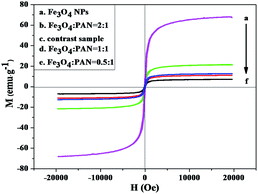 | ||
| Fig. 12 Hysteresis loops of the Fe3O4 NPs, the heterogeneous nanofiber yarns with different mass ratios of Fe3O4 NPs and of the homogeneous nanofiber yarns (contrast sample). | ||
| Samples | Saturation magnetization (Ms)/(emu g−1) | |
|---|---|---|
| Heterogeneous nanofiber yarns | Fe3O4 NPs | 67.37 |
Fe3O4![[thin space (1/6-em)]](https://www.rsc.org/images/entities/char_2009.gif) : :![[thin space (1/6-em)]](https://www.rsc.org/images/entities/char_2009.gif) PAN = 0.5 PAN = 0.5![[thin space (1/6-em)]](https://www.rsc.org/images/entities/char_2009.gif) : :![[thin space (1/6-em)]](https://www.rsc.org/images/entities/char_2009.gif) 1 1 |
7.11 | |
Fe3O4![[thin space (1/6-em)]](https://www.rsc.org/images/entities/char_2009.gif) : :![[thin space (1/6-em)]](https://www.rsc.org/images/entities/char_2009.gif) PAN = 1 PAN = 1![[thin space (1/6-em)]](https://www.rsc.org/images/entities/char_2009.gif) : :![[thin space (1/6-em)]](https://www.rsc.org/images/entities/char_2009.gif) 1 1 |
11.08 | |
Fe3O4![[thin space (1/6-em)]](https://www.rsc.org/images/entities/char_2009.gif) : :![[thin space (1/6-em)]](https://www.rsc.org/images/entities/char_2009.gif) PAN = 2 PAN = 2![[thin space (1/6-em)]](https://www.rsc.org/images/entities/char_2009.gif) : :![[thin space (1/6-em)]](https://www.rsc.org/images/entities/char_2009.gif) 1 1 |
21.28 | |
| Homogeneous nanofiber yarns | Contrast sample | 12.60 |
Formation mechanism for the nanofiber yarns
A formation mechanism for the heterogeneous nanofiber yarns is presented in Fig. 13. After the positive and negative high voltage are applied, the spinning solutions in the positive and negative spinnerets are synchronously ejected towards their opposites under the action of the electrostatic field, in which process the jets swing due to the instability of electrospinning. Meanwhile, an electrostatic induction phenomenon occurs in the copper funnel under the electrostatic field. The positively charged spinneret induces a negative charge on the edge of the funnel near the spinneret, whereas the negatively charged spinneret induces a positive charge on the edge of funnel near this spinneret,7,49 as revealed in Fig. 13a. In this case, the jets tend to be attracted to the edges of the copper funnel and the grounded metal wire so that the electric charges in the jets can be released. Thus at the beginning of the experiment, ordered nanofibers are formed between the edges of the copper funnel and the endpoint of the metal wire by electrostatic attraction of the charged copper funnel and the grounded metal wire as well as the swing of the jets, as displayed in Fig. 13a. It can be seen from Fig. 13b that a hollow-cone shaped nanofiber bundle is formed by rotating the funnel. Meanwhile, a twisted nanofiber yarn is generated between the tip of the nanofiber bundle and the endpoint of the metal wire. On slowly pulling down the metal wire, the length of the nanofiber yarn becomes longer. Once the nanofiber yarn has sufficient length, the nanofiber yarn is wrapped around the metal rod of the collecting device to realize automatic and continuous collection of nanofiber yarns, as depicted in Fig. 13c. Electrostatic induction always exists due to the existence of the electrostatic field throughout the experiment process. Therefore, the edge of the funnel opposite to the positively charged spinneret is always negatively charged and the edge of the funnel opposite to the negatively charged spinneret is always positively charged, as can be seen in Fig. 13.Conclusions
In summary, [Fe3O4/PANI/PAN]//[Eu(BA)3phen/PAN] fluorescent–electrical–superparamagnetic trifunctional heterogeneous nanofiber yarns were successfully prepared for the first time by using a conjugate electrospinning method. The average diameters of the heterogeneous nanofiber yarns and their internal nanofibers are 201 μm and 508 ± 8 nm, respectively. The heterogeneous nanofiber yarns have an obviously twisted structure and the nanofibers in the yarns exhibit high alignment and orientation. The heterogeneous nanofiber yarns contain two different types of nanofiber, namely [Fe3O4/PANI/PAN] electrical–superparamagnetic nanofibers and [Eu(BA)3phen/PAN] fluorescent nanofibers. Compared with [Fe3O4/PANI/Eu(BA)3phen/PAN] homogeneous nanofiber yarns, the heterogeneous nanofiber yarns have enhanced fluorescence owing to their peculiar structure, achieving the efficient separation of white-colored Eu(BA)3phen complexes from dark-colored Fe3O4 NPs and PANI. Besides, the superparamagnetism and electrical conductivity of the heterogeneous nanofiber yarns can be respectively tuned by changing the content of Fe3O4 NPs and PANI. The heterogeneous nanofiber yarns with unique properties are expected to be applied in the fields of electromagnetic shielding, gas sensors, drug targeting, flexible nano-devices, etc.Conflicts of interest
There are no conflicts of interest to declare.Acknowledgements
This work was financially supported by the National Natural Science Foundation of China (51573023, 50972020), the Natural Science Foundation of Jilin Province of China (20170101101JC), the Industrial Technology Research and Development Project of Jilin Province Development and Reform Commission (2017C051), the Science and Technology Research Planning Project of the Education Department of Jilin Province during the 13th Five-Year Plan Period (JJKH20170608KJ), and the Youth Foundation of Changchun University of Science and Technology (No. XQNJJ-2016-01).References
- A. Balaji, M. V. Vellayappan, A. A. John, A. P. Subramanian, S. K. Jaganathan, E. Supriyanto and S. I. A. Razak, RSC Adv., 2015, 5, 57984–58004 RSC.
- B. Khalid, X. Bai, H. Wei, Y. Huang, H. Wu and Y. Cui, Nano Lett., 2017, 17, 1140–1148 CrossRef CAS PubMed.
- A. Edwards, D. Jarvis, T. Hopkins, S. Pixley and N. Bhattarai, J. Biomed. Mater. Res., Part B, 2015, 103, 21–30 CrossRef PubMed.
- J. H. Lee, D. W. Shin, K. B. Nam, Y. H. Gim, H. S. Ko, D. K. Seo, G. Hui lee, Y. H. Kim, S. W. Kim, T. S. Oh and J. B. Yoo, Polymer, 2016, 84, 52–58 CrossRef CAS.
- F. Ko, Y. Gogotsi, A. Ali, N. Naguib, H. Ye, G. L. Yang, C. Li and P. Willis, Adv. Mater., 2003, 15, 1161–1165 CrossRef CAS.
- H. Okuzaki, T. Takahashi, N. Miyajima, Y. Suzuki and T. Kuwabara, Macromolecules, 2006, 39, 4276–4278 CrossRef CAS.
- S. H. Wu, B. Duan, P. H. Liu, C. D. Zhang, X. H. Qin and J. T. Butcher, ACS Appl. Mater. Interfaces, 2016, 8, 16950–16960 CAS.
- M. Abbasipour and R. Khajavi, Adv. Polym. Technol., 2013, 32, 21363 CrossRef.
- P. H. Liu, S. H. Wu, Y. Zhang, H. N. Zhang and X. H. Qin, Nanomaterials, 2016, 6, 121 CrossRef PubMed.
- X. R. Li, M. Y. Li, J. Sun, Y. Zhuang, J. J. Shi, D. W. Guan, Y. Y. Chen and J. W. Dai, Small, 2016, 12, 5009–5018 CrossRef CAS PubMed.
- Y. B. Wu, L. Wang, B. L. Guo and P. X. Ma, ACS Nano, 2017, 11, 5646–5659 CrossRef CAS PubMed.
- L. Wang, Y. B. Wu, B. L. Guo and P. X. Ma, ACS Nano, 2015, 9, 9167–9179 CrossRef CAS PubMed.
- Z. G. Xie, H. T. Niu and T. Lin, RSC Adv., 2015, 5, 15147–15153 RSC.
- Y. Lu and S. Ozcan, Nano Today, 2015, 10, 417–420 CrossRef CAS.
- C. M. Park, K. H. Chu, J. Heo, N. Her, M. Jang, A. Son and Y. Yoon, J. Hazard. Mater., 2016, 309, 133–150 CrossRef CAS PubMed.
- A. M. El-Toni, M. A. Habila, J. P. Labis, Z. A. Alothman, M. Alhoshan, A. A. Elzatahry and F. Zhang, Nanoscale, 2016, 8, 2510–2531 RSC.
- H. Y. Chen, D. C. Colvin, B. Qi, T. Moore, J. He, O. T. Mefford, F. Alexis, J. C. Gore and J. N. Anker, J. Mater. Chem., 2012, 22, 12802–12809 RSC.
- F. Chen, M. Chen, C. Yang, J. Liu, N. Q. Luo, G. W. Yang, D. H. Chen and L. Li, Phys. Chem. Chem. Phys., 2015, 17, 1189–1196 RSC.
- L. L. Li, C. Dong, Y. Q. Zhang, Z. T. Deng, X. L. Ren, X. W. Meng, F. Q. Tang, J. Ren and L. Zhang, Nanotechnology, 2007, 18, 405102 CrossRef.
- L. Li, C. Liu, L. Y. Zhang, T. T. Wang, H. Yu, C. G. Wang and Z. M. Su, Nanoscale, 2013, 5, 2249–2253 RSC.
- J. W. Lan, J. Y. Chen, N. X. Li, X. H. Ji, M. X. Yu and Z. K. He, Talanta, 2016, 151, 126–131 CrossRef CAS PubMed.
- H. L. Gao, L. Jiang, W. M. Wang, S. Y. Wang, H. X. Zhang and J. Z. Cui, Inorg. Chem., 2016, 55, 8898–8904 CrossRef CAS PubMed.
- B. Q. Shao, Q. Zhao, W. Z. Lv, M. M. Jiao, W. Lu and H. P. You, J. Mater. Chem. C, 2015, 3, 1091–1098 RSC.
- T. T. Li, H. W. Liu, Z. N. Wu, Y. Liu, Z. X. Guo and H. Zhang, Nanoscale, 2016, 8, 11792–11796 RSC.
- B. Shen, W. T. Zhai, M. M. Tao, J. Q. Ling and W. G. Zheng, ACS Appl. Mater. Interfaces, 2013, 5, 11383–11391 CAS.
- H. G. Wei, X. R. Yan, S. J. Wu, Z. P. Luo, S. Y. Wei and Z. H. Guo, J. Phys. Chem. C, 2012, 116, 25052–25064 CAS.
- N. German, A. Popov, A. Ramanaviciene and A. Ramanavicius, Polymer, 2017, 115, 211–216 CrossRef CAS.
- S. K. Simotwo, C. DelRe and V. Kalra, ACS Appl. Mater. Interfaces, 2016, 8, 21261–21269 CAS.
- X. Y. Xu and B. Yan, ACS Appl. Mater. Interfaces, 2015, 7, 721–729 CAS.
- H. Shao, Q. L. Ma, X. T. Dong, W. S. Yu, M. Yang, Y. Yang, J. X. Wang and G. X. Liu, Phys. Chem. Chem. Phys., 2015, 17, 21845–21855 RSC.
- X. Xi, J. X. Wang, X. T. Dong, Q. L. Ma, W. S. Yu and G. X. Liu, Chem. Eng. J., 2014, 254, 259–267 CrossRef CAS.
- Z. J. Wang, Q. L. Ma, X. T. Dong, D. Li, X. Xi, W. S. Yu, J. X. Wang and G. X. Liu, ACS Appl. Mater. Interfaces, 2016, 8, 26226–26234 CAS.
- Y. W. Liu, Q. L. Ma, M. Yang, X. T. Dong, Y. Yang, J. X. Wang, W. S. Yu and G. X. Liu, Chem. Eng. J., 2016, 284, 831–840 CrossRef CAS.
- D. C. Guo, Z. Y. Sun, L. D. Xu, Y. Gao, M. M. Dai, S. H. Wang, Q. Chang, C. Wang and D. G. Ma, Mater. Lett., 2015, 159, 159–162 CrossRef CAS.
- F. Bi, X. T. Dong, J. X. Wang and G. X. Liu, New J. Chem., 2015, 39, 3444–3451 RSC.
- N. Lv, J. L. Zhang, G. M. Li, X. Wang and J. Z. Ni, J. Phys. Chem. C, 2017, 121, 11926–11931 CAS.
- T. L. Chen and Y. A. Elabd, Electrochim. Acta, 2017, 229, 65–72 CrossRef CAS.
- F. Bi, X. T. Dong, J. X. Wang and G. X. Liu, ChemPlusChem, 2014, 79, 1713–1719 CAS.
- D. D. Yin, Q. L. Ma, X. T. Dong, N. Lv, J. X. Wang, W. S. Yu and G. X. Liu, ChemPlusChem, 2015, 80, 568–575 CrossRef CAS.
- X. Xi, Q. L. Ma, X. T. Dong, J. X. Wang, W. S. Yu and G. X. Liu, IEEE Trans. Nanotechnol., 2015, 14, 243–249 CrossRef CAS.
- L. Han, Q. L. Ma and X. T. Dong, RSC Adv., 2015, 5, 95674–95681 RSC.
- F. J. Miao, C. L. Shao, X. H. Li, N. Lu, K. X. Wang, X. Zhang and Y. C. Liu, Electrochim. Acta, 2015, 176, 293–300 CrossRef CAS.
- R. Zhao, X. Li, B. Sun, H. Ji and C. Wang, J. Colloid Interface Sci., 2017, 487, 297–309 CrossRef CAS PubMed.
- Q. J. Niu, J. X. Guo, B. L. Chen, J. Nie, X. D. Guo and G. P. Ma, Carbon, 2017, 114, 250–260 CrossRef CAS.
- Q. L. Ma, J. X. Wang, X. T. Dong, W. S. Yu and G. X. Liu, Chem. Eng. J., 2015, 260, 222–230 CrossRef CAS.
- Q. L. Ma, W. S. Yu, X. T. Dong, J. X. Wang, G. X. Liu and J. Xu, J. Nanopart. Res., 2012, 14, 1203 CrossRef.
- J. Tian, Q. L. Ma, X. T. Dong, W. S. Yu, M. Yang, Y. Yang, J. X. Wang and G. X. Liu, RSC Adv., 2016, 6, 36180–36191 RSC.
- D. H. Han, J. P. Wang and H. L. Luo, J. Magn. Magn. Mater., 1994, 136, 176–182 CrossRef CAS.
- J. X. He, K. Qi, Y. M. Zhou and S. Z. Cui, J. Appl. Polym. Sci., 2014, 131, 40137 Search PubMed.
| This journal is © The Royal Society of Chemistry 2017 |

