 Open Access Article
Simple synthesis of a double-shell hollow structured MnO2@TiO2 composite as an anode material for lithium ion batteries†
Yibo Su,
Jian Zhang,
Kai Liu,
Zeya Huang,
Xiancang Ren and
Chang-An Wang *
*
State Key Lab of New Ceramics and Fine Processing, School of Materials Science and Engineering, Tsinghua University, 100084, Beijing, China. E-mail: wangca@mail.tsinghua.edu.cn
First published on 28th September 2017
Abstract
A double-shell hollow structured MnO2@TiO2 anode material has been successfully synthesized through a two-step template method. The monodispersed carbon spheres synthesized through a hydrothermal method act as the templates. The inner part of the carbon template acts as a sacrificial template to form the void and the outer part of it plays the role of self-template to synthesize hollow MnO2 spheres. The composition, crystallinity, morphology, and valence state of the final product MnO2@TiO2 are characterized using X-ray diffraction, scanning electron microscopy, transmission electron microscopy, and X-ray photoelectron spectroscopy. The electrochemical performances of the double-shell hollow structured MnO2@TiO2 anode material have been comprehensively improved. The specific capacity of the composite retains 802 mA h g−1 at the current rate of 200 mA g−1 after 200 cycles, and it can still retain about 400 mA h g−1 at a higher current rate of 1 A g−1. Finally, a more detailed charging/discharging process of MnO2 is proposed.
1. Introduction
Lithium ion batteries have been widely used in portable electronic devices and electric vehicles because of their high energy density as well as long cycle life. Nevertheless, increasing capacity requirements make it necessary to develop new electrode materials, for example anode materials, to substitute current carbonaceous materials that possess a theoretical lithium capacity of 372 mA h g−1.1–3 Transition metal oxides are potential substitutions due to their common high theoretical specific capacity, based on a conversion reaction. One of the most promising candidates, MnO2, has attracted much attention since it was first used as an anode material by Poizot,4 because of its natural advantages: (1) MnO2 has a high theoretical specific capacity of 1232 mA h g−1, much higher than that of graphite;5–7 (2) MnO2 displays a moderate discharge voltage plateau of 0.4 V, which is lower than most of transition metal oxides, guaranteeing a high output voltage,8 and is higher than carbonaceous materials, making the precipitation of lithium metal harder under the circumstances of high current rate or low temperature, and further declare a safer working condition;10 (3) the natural resource of MnO2 is plentiful and its preparation process is mature and diverse.9–11 However, there are still some severe problems hindering the industrialization paces of MnO2 anode materials in that: (1) MnO2 shows a big volume effect during charge/discharge cycles, causing pulverization of itself and even electrode film; (2) MnO2 exhibits an extremely low electronic and ionic conductivity, leading to a bad rate capacity; (3) MnO2 displays a very low coulombic efficiency during the first cycle.12,13In order to solve these problems, different strategies have been attempted. In the beginning, the attention was focused on diminishing the particle size and making enough void for MnO2 to expand. A more elaborate structure could shorten the diffusion path of ions and alleviate the volume expansion. Thus, MnO2 nanomaterials with different crystalline phase, morphology and structure were synthesized, such as hollow α-MnO2 urchin and nanotubes,14,15 β-MnO2 nanorods,16 nanoporous γ-MnO2 hollow microspheres and nanocubes.17 Nevertheless, their cycle performances were still unsatisfied and the rate capacity was even worse as a result of the poor conductivity of MnO2. Therefore, so far, more and more works have been carried out to fabricate the composite materials of MnO2 with various conducting materials such as carbonaceous materials,18–21 organic conducting polymers22,23 and inorganic semiconductors.24–26 TiO2 is an ideal candidate of inorganic semiconductor for MnO2 coating not only because of its contribution to conductivity, but also it has a good structural stability during charge/discharge cycles due to a very small volume expansion. In addition, TiO2 is nontoxic, abundant, and not expensive so that it could be used as coating materials in industrial scale.27–29
In this paper, a new double-shell hollow structured MnO2@TiO2 has been synthesized via a two-step template method. The TiO2 coating improves the electrochemical performance of MnO2 and inner void provides a space for the volume effect during charge/discharge cycles. Moreover, this preparation method is a simple and short process, which is more adaptable to an efficient industrial production than all the above-mentioned works.
2. Experimental
2.1 Material synthesis
All reagents were used without further purification. In a typical procedure to prepare the double-shell hollow structured MnO2@TiO2 composite, carbon spheres with an average diameter of 200 nm were firstly fabricated through a hydrothermal method using glucose.30 0.15 g as-prepared carbon spheres and 0.3 g KMnO4 were separately dispersed in 50 ml and 20 ml distilled water through a 10 min ultrasonic processing, and then the two solutions were mixed together to react for 30 min to get C@MnO2. Finally, the brown product was filtered and washed with water and ethanol for three times.The synthesized C@MnO2 and 0.3 ml tetrabutyl titanate (TBOT) were dispersed in 50 ml anhydrous ethanol solution under ultrasonic treatment. 0.3 ml ammonium hydroxide diluted with 1.5 ml anhydrous ethanol was added into the solution dropwise, and the mixed solution reacted under magnetic stirring at 70 °C for 1 h. The precursor C@MnO2@TiO(OH)2 was obtained after centrifugal washing with absolute ethanol and drying for 6 h, and was finally annealed at 450 °C for 2 h to get MnO2@TiO2 with a double-shell structure.
2.2 Material characterization
The morphology of the samples was observed with a field-emission scanning electron microscope (FESEM, ZEISS MERLIN Compact, Germany). The structure and the element contents were characterized through TEM and EDS with a transmission electron microscope (TEM, JEOL JEM-2010, Japan). The crystal structure was analyzed by X-ray diffraction (XRD, Bruker D8 ADVANCE, Germany) with Cu Kα (λ = 0.154178 nm) radiation. The diffraction patterns were recorded from 10° to 80° at a scanning rate of 6° min−1. The valence state was implied with X-ray photoelectron spectroscopy (XPS) with an ESCALAB 250 Xi electron spectrometer from VG Scientific using 300 W Al Kα radiation.2.3 Battery assembling and electrochemical measurement
The working electrodes for electrochemical tests were prepared by a conventional procedure. First, 70 wt% of active material was dispersed with 15 wt% of super P and 15 wt% of polyvinylidene fluoride (PVDF) binder adequately in N-methyl-2-pyrrolidone (NMP), and the mixture was casted on a copper sheet. Then, after a drying and pressing process at 5 MPa, the electrode film was cut into several discs with a diameter of 12.5 mm. The average loading of active material was around 1 mg. At last, the LIR2032 coin cells were assembled in an Ar-filled glove box (Mikrouna (Super1220/750/900), China) by using the as-prepared electrodes as the working electrode, lithium foils as the counter and reference electrode, Celgard 2325 as the separator, and 1 M LiPF6 in EC![[thin space (1/6-em)]](https://www.rsc.org/images/entities/char_2009.gif) :
:![[thin space (1/6-em)]](https://www.rsc.org/images/entities/char_2009.gif) DEC (1
DEC (1![[thin space (1/6-em)]](https://www.rsc.org/images/entities/char_2009.gif) :
:![[thin space (1/6-em)]](https://www.rsc.org/images/entities/char_2009.gif) 1 by volume) as the electrolyte. The charge/discharge test was performed using a land cell test system (Land CT2001A, China) at various current rates between 0.01 V and 3.0 V (vs. Li/Li+) at ambient. Cyclic voltammetry (CV) was performed using an electrochemical workstation (CHI600E, China) between 0.01 V and 3.0 V at a sweep rate of 0.2 mV s−1. The electrochemical impedance spectra (EIS) of the cells was also measured on the electrochemical workstation over a frequency range from 105 Hz to 0.1 Hz with an amplitude of 5 mVrms.
1 by volume) as the electrolyte. The charge/discharge test was performed using a land cell test system (Land CT2001A, China) at various current rates between 0.01 V and 3.0 V (vs. Li/Li+) at ambient. Cyclic voltammetry (CV) was performed using an electrochemical workstation (CHI600E, China) between 0.01 V and 3.0 V at a sweep rate of 0.2 mV s−1. The electrochemical impedance spectra (EIS) of the cells was also measured on the electrochemical workstation over a frequency range from 105 Hz to 0.1 Hz with an amplitude of 5 mVrms.
3. Results and discussion
Double-shell structured MnO2@TiO2 composite and porous MnO2 were successfully achieved by a carbon-template method, as shown in Fig. 1. First, according to the previous work in our group,31 the core–shell structured C@MnO2 could be easily fabricated through the reaction in ambient between carbon spheres and KMnO4 with appropriate concentration in a short time. To certify the existing of carbon core, the C@MnO2 was calcined at 350 °C for 1 h, and the TEM images of the samples were shown in Fig. S1.† Considering the fact that the temperature range of decomposition of carbon spheres is 300–500 °C, which is denoted in Fig. S2,† the small void in Fig. S1(b)† arises clearly as a result of the oxidative decomposition of the carbon core. Then, some of the C@MnO2 samples were treated with TBOT to coat TiO(OH)2 outside the C@MnO2 spheres and finally calcined at 450 °C for 2 h to prepare MnO2@TiO2 composite, while the others were directly heated to 450 °C for 2 h to fabricate porous MnO2, which is depicted by TEM in Fig. S1(c and d).† It is noteable that the porous MnO2 possesses an interesting sphere structure constructed by crossing crystalline MnO2 nanorods. For convenience, the C@MnO2, MnO2@TiO2 and the porous MnO2 are named as CM, MT-450 and M-450, respectively.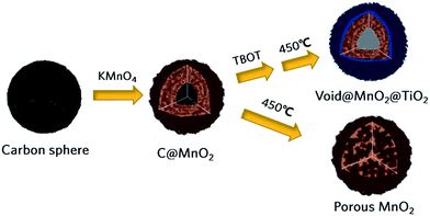 | ||
| Fig. 1 Schematic synthetic route for double shell structured MnO2@TiO2 composite and porous MnO2 in contrast. | ||
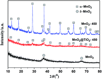
Fig. 2 shows X-ray diffraction (XRD) patterns of as-prepared C@MnO2, MT-450 and M-450. Although the XRD pattern of CM displays poor crystallinity, it could still be indexed as δ-phase MnO2 (JCPDS no. 80-1098), similar to the previous reports.32 There are the same diffraction peaks for MT-450 and M-450 appearing at 2θ = 28.8, 37.5 and 60.3°, which can be ascribed to the (310), (211) and (521) reflections of α-MnO2 (PDF-44-0141), respectively. The diffraction peaks of TiO2 in MT-450 are so weak because of the very thin shell covered on the surface of MnO2. It is worth noticing that MT-450 exhibits worse crystallinity than M-450, which demonstrates the resistant effect of TiO2 for the crystalline process of MnO2. A relatively worse crystallinity contributes to a higher first-cycle coulombic efficiency, because the insertion reaction of MnO2 at a relatively high voltage (>2 V) is nearly irreversible,9,33 which will be further discussed below.
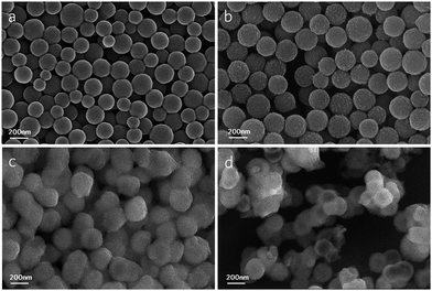
Field-emission scanning electron microscope (FESEM) was used to characterize the morphology of all the typical samples in each of the steps, as can be seen in Fig. 3. And the four images are all photographed at the same magnification. The carbon spheres in Fig. 3a have a good monodispersity and an average diameter of 150–200 nm. Comparatively, the average diameter of C@MnO2 in Fig. 3b is a little bigger than carbon spheres as a result of the Kirkendall effect, based on which Li31 set forth a “surface-softening” diffusion model to illustrate the whole process in detail. Under the treatment of KMnO4, the long tangled chains of aromatic nuclei with reactive oxygen functional groups decomposes into short carbon chains, which is capable of diffusing through the MnO2 layer and maintains reducibility at the same time. In other words, the short carbon chains in carbon spheres diffuse outward, meanwhile the KMnO4 diffuses inward and react with short carbon chains to form MnO2 outside the spheres causing a relatively bigger diameter. After coating with TiO(OH)2, voids appear in some of the spheres in Fig. 3c due to good solubility of short carbon chains in anhydrous ethanol. In the process of aging at 70 °C, short carbon chains in some spheres tend to dissolve out into the anhydrous ethanol, thus form the voids. In addition, there are some solid spheres without voids, probably because the TiO(OH)2 shell is dense enough to prevent short carbon chains from dissolving out. Finally after calcination, the spheres in goal product MT-450 (Fig. 3d) are almost all hollow spheres.
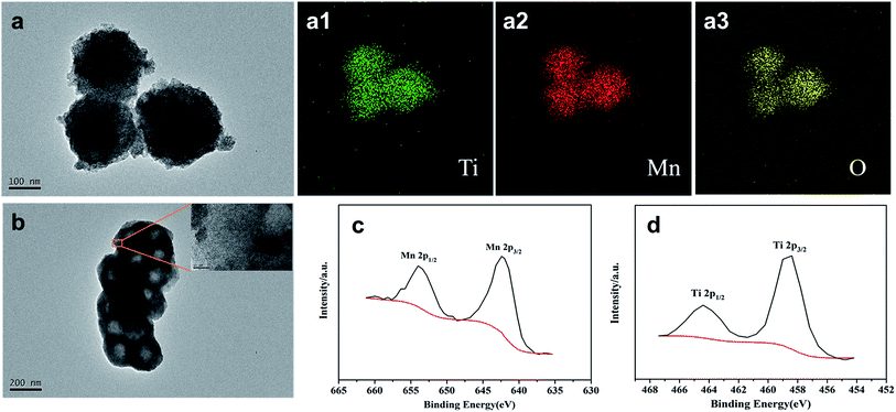
To further verify the components and structure of the resulting product MT-450, transmission electron microscope (TEM) and X-ray photoelectron spectroscopy (XPS) tests were carried out as shown in Fig. 4. According to Fig. 4a (containing 4a1–4a3), the C@MnO2@TiO(OH)2 precursor spheres partly consist of Mn, Ti and O atoms, announcing a successful coating of TiO(OH)2. From Fig. 4b, it is clearly to see the hollow structure of the goal product MT-450 as well as the amorphous TiO2 in the high-resolution TEM image, which is the magnification of the marked zone in Fig. 4b. EDS has also been conducted to certify the component of MT-450, which could be found in Fig. S3.† The chemical composition of MT-450 was deeply characterized by using XPS, as illustrated in Fig. 4(c and d). The peaks at 642.3 eV, 654.0 eV, 458.5 eV and 464.3 eV are assigned to Mn 2p3/2, Mn 2p1/2, Ti 2p3/2 and Ti 2p1/2, respectively, indicating that Mn and Ti exist in MK-450 mainly in the form of Mn4+ and Ti4+, which agrees with the reported values.34–37
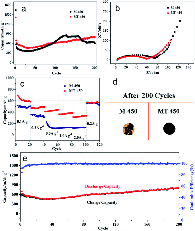
MT-450 is compared with M-450 (and M-350, discussed in Fig. S4†) in terms of cycling performance, electrochemical impedance and rate capacity, tested in coin cells with lithium foil as the reference and counter electrode. The obtained results are presented in Fig. 5. According to Fig. 5a, MT-450 displays a better specific capacity retention of 802 mA h g−1 (comparing to M-450 of 605 mA h g−1) after 200 cycles at a current rate of 200 mA h g−1. This improvement could be attributed to the protection of TiO2, which avoids direct contact between MnO2 and electrolyte, thus alleviating side reactions and volume effect during cycles. The tendency of capacity decrease before the first 30 cycles suggesting that fresh SEI keeps generating until the 30th cycle.36 As for the notable rising of specific capacity, it is common for MnOx anode materials,29 which is attributed to an activation process of the active materials.38
Fig. 5b presents similar electrochemical impedance spectra (EIS) of M-450 and MT-450. The semicircle at high frequencies of MT-450 is relatively smaller, which implies a lower charge transfer resistance (Rct) between materials and the electrolyte. That is to say, the coating of TiO2 promotes the charge transfer of MnO2 and would further improve its rate capacity. The slope of the straight line at low frequencies of the two samples are nearly the same, which reflecting the same diffusion of lithium ions in the electrolyte.36 Fig. 5c shows the rate capacity of the two samples at different current densities of 0.1 A g−1, 0.2 A g−1, 0.5 A g−1, 1 A g−1 and 2 A g−1 within 120 cycles. The two samples have similar behaviors when the current rate is lower or equal to 0.2 A g−1. While, once the current rate rises to 0.5 A g−1 or bigger, its specific capacity declines sharply to an extremely low value of about 130 mA h g−1. Comparatively, the MT-450 still presents a specific capacity of around 450 mA h g−1 and 400 mA h g−1 respectively at the current rate of 0.5 A g−1 and 1 A g−1, even with more than 300 mA h g−1 left at 2 A g−1, which proves that the coating of TiO2 does contribute to its rate capacity. Without the protection of TiO2, at last, powdering and stripping of the active material of M-450, as photographed in Fig. 5d, leads to a rapid capacity fading. Fig. 5e shows the good cyclability of the MT-450 at a current rate of 200 mA g−1 within 200 cycles, accompanied by an average coulombic efficiency of more than 99%.
From the cyclic voltammograms (CV) of MT-450 and M-450 in different cycles, shown in Fig. 6, it can be clearly seen that a new pair of charge/discharge peaks emerges at about 1 V and 2.1 V after 200 cycles. According to the reported work, there exists two charging/discharging process for MnOx anode materials.39,40 However, as far as we know, there is little work have been reported demonstrating the mechanism of the two charging/discharging process of MnO2. Herein, it is going to be further discussed.
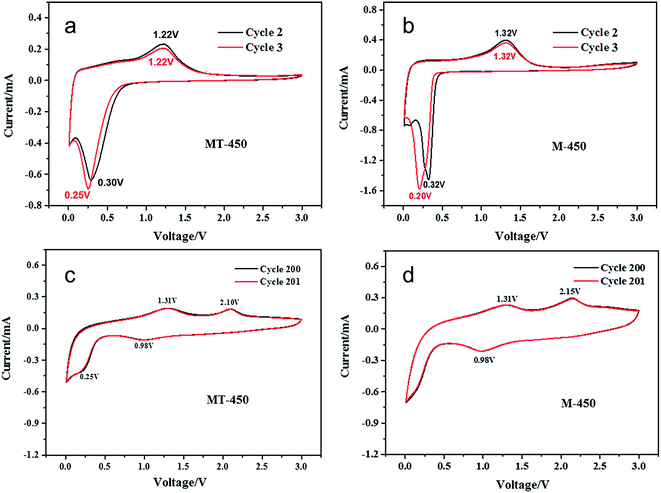 | ||
| Fig. 6 Cyclic voltammograms at a scan rate of 0.2 mV s−1 in the range of 0.01–3 V of MT-450 and M-450 in cycle 2–3 (a, b) and cycle 200–201 (c, d). | ||
In this work, the MnO2 nanospheres are crystallized as α-MnO2, as shown in Fig. 2. At the beginning of discharging process, lithium ions insert into the tunnels of α-MnO2 without affecting its structure. Then, with inserted lithium ions increasing and the voltage lowing down, the Mn and O atoms get reorganized and gradually resulting in more stabilized LixMnO2 structures with defect rock salt character until the voltage is lower than 0.5 V.9 After that, the new coming Li would replace Mn through a reduction reaction, forming Mn and Li2O. The reactions are:
| xLi + MnO2 = LixMnO2 | (1) |
| (4 − x)Li + LixMnO2 = Mn + 2Li2O (0 < x < 1) | (2) |
During charging, the process is reversed. However, for LixMnO2, it is hard to extract all of its Li+ because it's more stable to keep a rock salt structure. The reactions are written as follows.
| Mn + 2Li2O = (4 − x)Li + LixMnO2 (0 < x < 1) | (3) |
| LixMnO2 = (x − y)Li + LiyMnO2 (0 < y < x < 1) | (4) |
Further, for the next discharging process, because of the incompletion of lithium extraction for LixMnO2, the high-voltage discharging reaction is adapted to:
| (x − y)Li + LiyMnO2 = LixMnO2 (0 < y < x < 1) | (5) |
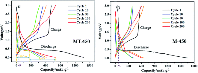
Apparently, the capacity of this part is determined by process (4), and it could contribute a capacity proportion of less than 25%, which is corresponding to the valence change from Mn4+ to Mn3+. There exists different mechanism of lithium insertion in different range of voltage, therefore, the discharge capacity should be divided into two part by the threshold of voltage platform, named part A and B in this work as illustrated in Fig. 7. After 200 cycles, part 200-A and 200-B in Fig. 7 are corresponding to process (5) and (2), respectively.
The charge/discharge curves of cycle 1, 10, 50, 100 and 200 of the two samples are put together for comparison, as shown in Fig. 7(a) and (b). From the curves of cycle 1, the discharge capacity corresponding to the voltage range from 3 V to 2 V could be read as 47 mA h g−1 (a) and 75 mA h g−1 (b), respectively. This part of discharge capacity is useless and even harmful for the anode material because of its high voltage platform as well as its poor reversibility, leading to a lower first coulombic efficiency. Comparatively, the MT-450 realizes a smaller discharge capacity of 47 mA h g−1 owing to a worse crystallinity than M-450, and further attains to a higher first coulombic efficiency.
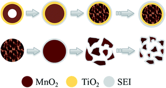
After 200 cycles, many of the active materials of M-450 collapse completely with massive SEI, while MT-450 displays an eminent structural stability, as shown in Fig. 8. Because MnO2 is well confined in the TiO2 shell in MT-450 (verified in Fig. S5†). MnO2 can only expand inwards in the process of lithium insertion. The inner MnO2 hollow spheres end up into porous spheres, which is also an eligible structure for a superior anode material. Based on the above characterizations, a schematic of morphological evolution process of MT-450 and M-450 during cycling is illustrated in Fig. 9. The structure of MT-450 will switch from double-shell hollow structure to porous core–shell structure and maintain stable in hundreds of cycles. Without protective TiO2 shell, MnO2 will end up with pieces of fragments wearing an increasing thickness of SEI during cycles. From Fig. S5,† we can find that the atom percent ratio of Mn![[thin space (1/6-em)]](https://www.rsc.org/images/entities/char_2009.gif) :
:![[thin space (1/6-em)]](https://www.rsc.org/images/entities/char_2009.gif) Ti is about 5
Ti is about 5![[thin space (1/6-em)]](https://www.rsc.org/images/entities/char_2009.gif) :
:![[thin space (1/6-em)]](https://www.rsc.org/images/entities/char_2009.gif) 1. So, the content of TiO2 is calculated as around 15.5 wt%. The content of TiO2 have to be moderate because a high TiO2 contents will cause a capacity decrease owing to the low theoretical specific capacity of TiO2 (335 mA h g−1, far less than that of MnO2 with 1232 mA h g−1), while a low TiO2 contents will result in an incomplete coating, which will greatly discount the protection effect of TiO2.
1. So, the content of TiO2 is calculated as around 15.5 wt%. The content of TiO2 have to be moderate because a high TiO2 contents will cause a capacity decrease owing to the low theoretical specific capacity of TiO2 (335 mA h g−1, far less than that of MnO2 with 1232 mA h g−1), while a low TiO2 contents will result in an incomplete coating, which will greatly discount the protection effect of TiO2.
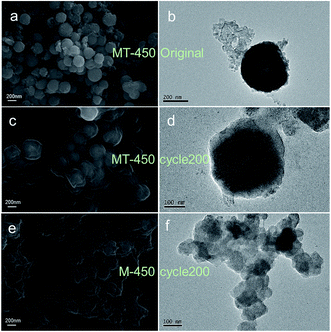 | ||
| Fig. 8 SEM images and TEM images of original state (a, b) and the 200th cycle state (c, d) of the MT-450 and the state of M-450 after 200 cycles (e, f) on copper foil. The component of (d) is certified with EDS, whose results is seen in Fig. S5.† | ||
4. Conclusions
The double-shell structured MnO2@TiO2 anode material has been successfully synthesized through a simple two-step template method. The outer part of carbon template spheres reacts with KMnO4 to form “hollow” MnO2, and then, after a TiO2 coating, the inner part is moved out by calcination to form “void”, making the MnO2 truly hollow. In the MnO2@TiO2 composite, both of MnO2 and TiO2 display poor crystallinity. TiO2 shell could improve the electrochemical performances of MnO2@TiO2 in the following four aspects: (1) TiO2 shell hinders the crystalline process of MnO2, leading to a worse crystallinity than pure MnO2 at the same temperature, which is beneficial to a higher first-cycle coulombic efficiency. (2) TiO2 shell protects MnO2 from contacting electrolyte directly, and avoids unnecessary loss of active material to form solid–electrolyte interface (SEI). (3) TiO2 shell confines MnO2 and compels it to expand only inwards to avoid volume effect during cycles. (4) TiO2 shell enhances the conductivity of MnO2 to further improve its rate capacity. At last, a more detailed charging/discharging process of MnO2 is firstly put forward.Conflicts of interest
There are no conflicts to declare.Acknowledgements
The authors would like to acknowledge the grants from the National Natural Science Foundation of China (NSFC-No. 51572145).References
- B. Xu, C. R. Fell, M. F. Chi and Y. S. Meng, Identifying surface structural changes in layered Li-excess nickel manganese oxides in high voltage lithium ion batteries: A joint experimental and theoretical study, Energy Environ. Sci., 2011, 4, 2223–2233 CAS.
- Y. M. Sun, H. W. Lee, Z. W. Seh, N. Liu, J. Sun, Y. Z. Li and Y. Cui, High-capacity battery cathode prelithiation to offset initial lithium loss, Nat. Energy, 2016, 1, 1–7 Search PubMed.
- W. M. Zhang, X. L. Wu, J. S. Hu, Y. G. Guo and L. J. Wan, Carbon coated Fe3O4 nanospindles as a superior anode material for Lithium-Ion batteries, Adv. Funct. Mater., 2008, 18, 3941–3946 CrossRef CAS.
- P. Poizot, S. Laruelle, S. Grugeon, L. Dupontand and J. M. Tarascon, Nano-sized transition-metal oxides as negative-electrode materials for lithium-ion batteries, Nature, 2000, 407, 496–499 CrossRef CAS PubMed.
- A. L. M. Reddy, M. M. Shaijumon, S. R. Gowda and P. M. Ajayan, Coaxial MnO2/Carbon Nanotube Array Electrodes for High-Performance Lithium Batteries, Nano Lett., 2009, 9, 1002–1006 CrossRef CAS PubMed.
- C. X. Guo, M. Wang, T. Chen, X. W. Lou and C. M. Li, A Hierarchically Nanostructured Composite of MnO2/Conjugated Polymer/Graphene for High-Performance Lithium Ion Batteries, Adv. Energy Mater., 2011, 1, 736–741 CrossRef CAS.
- Y. Wang, Z. J. Han, S. F. Yu, R. R. Song, H. H. Song, K. (Ken) Ostrikov and H. Y. Yang, Core-leaf onion-like carbon/MnO2 hybrid nano-urchins for rechargeable lithium-ion batteries, Carbon, 2013, 64, 230–236 CrossRef CAS.
- J. Cabana, L. Monconduit, D. Larcher and M. R. Palacín, Beyond Intercalation- Based Li-Ion Batteries: The State of the Art and Challenges of Electrode Materials Reacting Through Conversion Reactions, Adv. Mater., 2010, 22, 170–192 CrossRef PubMed.
- M. M. Thackeray, Manganese Oxides for Lithium Batteries, Prog. Solid State Chem., 1997, 25, 1–71 CrossRef CAS.
- J. J. Zhang and A. S. Yu, Nanostructured transition metal oxides as advanced anodes for lithium-ion batteries, Sci. Bull., 2015, 60, 823–838 CrossRef CAS.
- W. H. Ryu, D. W. Han, W. K. Kim and H. S. Kwon, Facile route to control the surface morphologies of 3D hierarchical MnO2 and its Al self-doping phenomenon, J. Nanopart. Res., 2013, 13, 4777–4784 CrossRef.
- Y. F. Deng, L. N. Wan, Y. Xie, X. S. Qin and G. H. Chen, Recent advances in Mn-based oxides as anode materials for lithium ion batteries, RSC Adv., 2014, 4, 23914–23935 RSC.
- A. L. M. Reddy, M. M. Shaijumon, S. R. Gowda and P. M. Ajayan, Coaxial MnO2/Carbon Nanotube Array Electrodes for High-Performance Lithium Batteries, Nano Lett., 2009, 9, 1002–1006 CrossRef CAS PubMed.
- B. Li, G. Rong, Y. Xie, L. Huang and C. Feng, Low-Temperature Synthesis of α-MnO2 Hollow Urchins and Their Application in Rechargeable Li+ Batteries, Inorg. Chem., 2006, 45, 6404–6410 CrossRef CAS PubMed.
- L. H. Li, C. Y. Nan, J. Lu, Q. Peng and Y. D. Li, α-MnO2 nanotubes: high surface area and enhanced lithium battery properties, Chem. Commun., 2012, 48, 6945–6947 RSC.
- X. P. Fang, X. Lu, X. W. Guo, Y. Mao, Y. S. Hu, J. Z. Wang, Z. X. Wang, F. Wu, H. K. Liu and L. Q. Chen, Electrode reactions of manganese oxides for secondary lithium batteries, Electrochem. Commun., 2010, 12, 1520–1523 CrossRef CAS.
- J. Zhao, Z. Tao, J. Liang and J. Chen, Facile Synthesis of Nanoporous γ-MnO2 Structures and Their Application in Rechargeable Li-Ion Batteries, Cryst. Growth Des., 2008, 8, 2799–2805 CAS.
- H. Xia, M. Lai and L. Lu, Nanoflaky MnO2/carbon nanotube nanocomposites as anode materials for lithium-ion batteries, J. Mater. Chem., 2010, 20, 6896–6902 RSC.
- A. P. Yu, H. W. Park, A. Davies, D. C. Higgins, Z. W. Chen and X. C. Xiao, Free-Standing Layer-By-Layer Hybrid Thin Film of Graphene-MnO2 Nanotube as Anode for Lithium Ion Batteries, J. Phys. Chem. Lett., 2011, 2, 1855–1860 CrossRef CAS.
- Y. Zhang, H. Liu, Z. H. Zhu, K. W. Wong, R. Mi, J. Mei and W. M. Lau, A green hydrothermal approach for the preparation of graphene/α-MnO2 3D network as anode for lithium ion battery, Electrochim. Acta, 2013, 108, 465–471 CrossRef CAS.
- Y. Y. Li, Q. W. Zhang, J. L. Zhu, X. L. Wei and P. K. Shen, An extremely stable MnO2 anode incorporated with 3D porous graphene-like networks for lithium-ion batteries, J. Mater. Chem. A, 2014, 2, 3163–3168 CAS.
- J. X. Li, M. Z. Zou, Y. Zhao, Y. B. Lin, H. Lai, L. H. Guan and Z. G. Huang, Coaxial MWNTs@MnO2 confined in conducting PPy for kinetically efficient and long-term lithium ion storage, Electrochim. Acta, 2013, 111, 165–171 CrossRef CAS.
- M. S. Wu, P. C. J. Chiang, J. T. W. Xiao, J. S. Chen, Q. Lu and X. W. Lou, Porous Spheres Assembled from Polythiophene (PTh)-Coated Ultrathin MnO2 Nanosheets with Enhanced Lithium Storage Capabilities, J. Phys. Chem. C, 2010, 114, 12048–12051 Search PubMed.
- L. L. Xing, B. He, Y. X. Nie, P. Deng, C. X. Cui and X. Y. Xue, SnO2–MnO2–SnO2 sandwich-structured nanotubes as high-performance anodes of lithium ion battery, Mater. Lett., 2013, 105, 169–172 CrossRef CAS.
- Q. Wang, D. A. Zhang, Q. Wang, J. Sun, L. L. Xing and X. Y. Xue, High electrochemical performances of α-MoO3@MnO2 core-shell nanorods as lithium-ion battery anodes, Electrochim. Acta, 2014, 146, 411–418 CrossRef CAS.
- J. Y. Liao, D. Higgins, G. Lui, V. Chabot, X. C. Xiao and Z. W. Chen, Multifunctional TiO2–C/MnO2 Core–Double-Shell Nanowire Arrays as High-Performance 3D Electrodes for Lithium Ion Batteries, Nano Lett., 2013, 13, 5467–5473 CrossRef CAS PubMed.
- D. A. Zhang, Q. Wang, Q. Wang, J. Sun, L. L. Xing and X. Y. Xue, Core–shell SnO2@TiO2–B nanowires as the anode of lithium ion battery with high capacity and rate capability, Mater. Lett., 2014, 128, 295–298 CrossRef CAS.
- J. Jin, S. Z. Huang, J. Liu, Y. Li, D. S. Chen, H. E. Wang, Y. Yu, L. H. Chen and B. L. Su, Design of new anode materials based on hierarchical, three dimensional ordered macro-mesoporous TiO2 for high performance lithium ion batteries, J. Mater. Chem. A, 2014, 2, 9699–9708 CAS.
- D. Wua, R. Yang, Q. X. Sun, L. She, W. X. Jia, R. She, M. Jiang, W. P. Ding and L. M. Peng, Simple Synthesis of TiO2/MnOx Composite with Enhanced Performances as Anode Materials for Li-Ion Battery, Electrochim. Acta, 2016, 211, 832–841 CrossRef.
- X. M. Sun and Y. D. Li, Colloidal Carbon Spheres and Their Core/Shell Structures with Noble-Metal Nanoparticles, Angew. Chem., Int. Ed., 2004, 43, 597–601 CrossRef PubMed.
- S. Li and C. A. Wang, Design and synthesis of hierarchically porous MnO2/carbon hybrids for high performance electrochemical capacitors, J. Colloid Interface Sci., 2015, 438, 61–67 CrossRef CAS PubMed.
- P. Ragupathy, D. H. Park, G. Campet, H. N. Vasan, S. J. Hwang, J. H. Choy and N. Munichandraiah, Remarkable Capacity Retention of Nanostructured Manganese Oxide upon Cycling as an Electrode Material for Supercapacitor, J. Phys. Chem. C, 2009, 113, 6303–6309 CAS.
- V. Pralong, Lithium intercalation into transition metal oxides: A route to generate new ordered rock salt type structure, Prog. Solid State Chem., 2009, 37, 262–277 CrossRef CAS.
- X. F. Xie and L. Gao, Characterization of a manganese dioxide/carbon nanotube composite fabricated using an in situ coating method, Carbon, 2007, 45, 2365–2373 CrossRef CAS.
- Z. C. Yang, C. H. Tang, H. Gong, X. Li and J. Wang, Hollow spheres of nanocarbon and their manganese dioxide hybrids derived from soft template for supercapacitor application, J. Power Sources, 2013, 240, 713–720 CrossRef CAS.
- X. Q. Chen, H. B. Lin, X. W. Zheng, X. Cai, P. Xia, Y. M. Zhu, X. P. Li and W. S. Li, Fabrication of core–shell porous nanocubic Mn2O3@TiO2 as a high-performance anode for lithium ion batteries, J. Mater. Chem. A, 2015, 3, 18198–18206 CAS.
- R. Wang, N. Sakai, A. Fujishima, T. Watanabe and K. Hashimoto, Studies of Surface Wettability Conversion on TiO2 Single-Crystal Surfaces, J. Phys. Chem. B, 1999, 103, 2188–2194 CrossRef CAS.
- J. Yue, X. Gu, L. Chen, N. N. Wang, X. L. Jiang, H. Y. Xu, J. Yang and Y. T. Qian, General synthesis of hollow MnO2, Mn3O4 and MnO nanospheres as superior anode materials for lithium ion batteries, J. Mater. Chem. A, 2014, 2, 17421–17426 CAS.
- B. Liu, D. Li, Z. J. Liu, L. L. Gu, W. H. Xie, Q. Li, P. Q. Guo, D. Q. Liu and D. Y. He, Carbon-wrapped MnO nanodendrites interspersed on reduced graphene oxide sheets as anode materials for lithium-ion batteries, Appl. Surf. Sci., 2017, 394, 1–8 CrossRef CAS.
- M. Kundu, C. C. A. Ng, D. Y. Petrovykh and L. F. Liu, Nickel foam supported mesoporous MnO2 nanosheet arrays with superior lithium storage performance, Chem. Commun., 2013, 49, 8459–8461 RSC.
Footnote |
| † Electronic supplementary information (ESI) available. See DOI: 10.1039/c7ra09628c |
| This journal is © The Royal Society of Chemistry 2017 |

