 Open Access Article
Creative Commons Attribution 3.0 Unported Licence
Synthesis of polypyrrole nanoparticles and their applications in electrically conductive adhesives for improving conductivity†
Jiayue Wen a,
Yanhong Tian*a,
Zhipeng Meib,
Weizhen Wub and
Yanqing Tian
 *b
*b
aState Key Lab of Advanced Welding and Joining, Harbin Institute of Technology, Harbin, 150001, China. E-mail: tianyh@hit.edu.cn
bDepartment of Materials Science and Engineering, Southern University of Science and Technology, Shenzhen, 518055, China. E-mail: tianyq@sustc.edu.cn
First published on 21st November 2017
Abstract
Herein, we report an innovative application of doping conjugated-polypyrrole nanoparticles (PPy NPs) into electrically conductive adhesives (ECAs) to prepare low-electrical resistivity interconnecting materials. PPy NPs were synthesized via a facile one-step chemical oxidative polymerization method at room temperature with the average diameter as small as 86.8 nm. Particles' diameters and dispersity were manipulated under different polymerization conditions through the adjustment of weight percentages and molecular weights of polyvinylpyrrolidone (PVP) as the surfactants. Results showed that higher concentrations of PVP and the longer chains of PVPs resulted in smaller diameters of PPy NPs. We also found that a suitable portion of ethanol in the polymerization mixtures gives rise to a better dispersity than that observed in mixtures without ethanol. When a small amount of PPy NPs was added into traditional epoxy resin-based and silver-flakes-filled ECAs, the resistance measurements showed an enhancement in the electrical conductivity, or in other words, a reduction in resistivity significantly. For example, the electrical resistivity of 70 wt% silver-filled ECAs was reduced from 1.6 × 10⁻³ Ω cm to 9.4 × 10⁻⁵ Ω cm by using only 2.5 wt% PPy NPs as the dopants. Thus, our results confirmed new applications of PPy NPs in the field of ECAs for decreasing the resistance, reducing the dosage of silver in ECAs, and achieving flexible devices. Finally, flexible electrical patterns were printed on paper and polyimide substrates were used as conducting circuits to light LED devices.
1. Introduction
Tin–lead (Sn–Pb) solders as traditional joining materials have been known to possess low melting points, low cost and good wettability, making them widely applicable in electronic packaging. However, to decrease the hazard of lead to human nervous system and the environment, the Sn–Pb solders were banned to be used as interconnecting materials in electronic packaging under the Waste Electrical and Electronic Equipment (WEEE) and Restriction of Hazardous Substances (RoHS) directives.1,2 Therefore, lead-free solders, such as eutectic SnAgCu solders, are generally used in spite of higher melting point, worse wettability and higher cost.Other than traditional lead-free solders, electrically conductive adhesives (ECAs) are defined as alternative solders to tin–lead solders, which possess a lot of advantages with low operating temperature for fragile integrated circuits, high flexibility for future wearable electronics, wide applications in fine-pitch packaging, and excellent compatibility with non-wetting substrates including ceramic substrates, glass substrates or polymer film substrates.3–6 Besides being used as traditional joining materials, ECAs can be easily printed to high conductive circuits. Thus, ECAs composed of polymer matrices and conductive fillers have various applications in printing flexible circuits,7,8 wearable and stretchable radio-frequency identification (FRID) devices,9 capacitive touch panel modules10 and so on. However, the disadvantage of ECAs is their high electrical resistance, which is usually caused by some lubricant residues (mostly fatty acids) on the surface of conductive fillers during the preparation processes by milling.
Although adding more conductive fillers into the ECAs can decrease the electrical resistance, it compromises the cost and fluidity for printing. Therefore, numerous significant endeavors have been focused on how to enhance the conductivity of ECAs or reduce the percolation threshold for a lower cost,11 which can be divided into three approaches: (1) surface treatment, (2) adding nano conductive materials, and (3) sintering nano fillers or low melting point alloys. Some inorganic acids and short-chain dibasic acids were used to replace fatty acids on the surface of silver flakes to reduce tunneling resistance.12–14 Silane coupling agents were used to improve the compatibility of resins and conductive fillers, which are also beneficial for the mechanical properties of ECAs.15–17 However, when silver flakes or silver nanoparticles were used as the conducting fillers, even a small amount of semiconducting silver oxide (Ag2O), from long time storage or high temperature curing process, impaired the conductivity of ECAs. Therefore, reductants such as sodium borohydride (NaBH4), Iodine (I2) or terephthalaldehyde have been used to remove Ag2O from the surface of Ag flakes.18,19 Besides the surface treatments, the second approach is to add nanomaterials-based conducting materials into ECAs to fill the gap between conductive fillers and increase conductive paths. This approach of using nanomaterials as the dopants into ECAs could drastically enhance the electrical conductivity of ECAs. Some nanomaterials have been synthesized and investigated with various morphologies including silver nanoparticles,20 silver nanowires,21 modified reduced graphene oxide,22 or modified carbon nanotubes.12,23,24 In addition to two approaches stated above, in terms of sintering in ECAs, low temperature bonding nanomaterials and low melting point alloys are suitable for sintering between Ag flakes and fillers during the curing process at temperatures usually lower than 200 °C.25–27
On the other hand, conjugated polymers possessing excellent electrical properties, magnetic properties, optical properties, wettability, and so on have drawn considerable attention for applications in microelectronic devices, chemical or biological sensors, ion selective electrodes, electromagnetic interference (EMI) shielding, and conductive coatings for nanomaterials.28–30 Besides the abovementioned applications, conjugated polymers as intrinsic semi-conductors were applied as corrosion-resistant materials.31–33 Thus, these characteristics of conjugated polymers would also be beneficial to ECAs if the polymers were fabricated into nanoparticles and used as fillers in ECAs. However, there were only several reports about utilizing soluble conjugated polymers to improve the electrical conductivity,34,35 and few studies were focused on using conjugated polymer nanoparticles to reduce the resistance, particularly in ECAs.
Herein, we introduce a facile method to synthesize polypyrrole nanoparticles (PPy NPs) with different diameters under various preparation conditions as fillers for ECAs. These nanostructured PPy NPs were mixed into conventional Ag-flakes-filled ECAs to improve the conductivity of ECAs. Finally, we successfully printed these PPy NPs-doped ECAs on flexible substrates like papers and polyimides to light the light-emitting diodes (LED).
2. Experimental
2.1 Materials
Pyrrole (Py) was purchased from Adamas Reagent Co., Ltd, Shanghai, China. Polyvinylpyrrolidone (PVP, K15 Mw10![[thin space (1/6-em)]](https://www.rsc.org/images/entities/char_2009.gif) 000, K30 Mw58
000, K30 Mw58![[thin space (1/6-em)]](https://www.rsc.org/images/entities/char_2009.gif) 000, K90 Mw13
000, K90 Mw13![[thin space (1/6-em)]](https://www.rsc.org/images/entities/char_2009.gif) 00
00![[thin space (1/6-em)]](https://www.rsc.org/images/entities/char_2009.gif) 000), methylhexahydrophthalic anhydride (MeHHPA), 2,4,6-tris(dimethylaminomethyl)phenol (DMP-30) and ethanol were purchased from Aladdin, Shanghai, China. PVP K60 Mw360
000), methylhexahydrophthalic anhydride (MeHHPA), 2,4,6-tris(dimethylaminomethyl)phenol (DMP-30) and ethanol were purchased from Aladdin, Shanghai, China. PVP K60 Mw360![[thin space (1/6-em)]](https://www.rsc.org/images/entities/char_2009.gif) 000 was purchased from Energy Chemical, Shanghai, China. Ferric chloride hexahydrate (FeCl3·6H2O) was purchased from Tianjin Fuchen Chemical Reagents Factory. Ag flakes with average diameters of 8–10 μm were purchased from Bolong Silver Industry, Changsha, China. Liquid bisphenol-A epoxy resin (E51) was purchased from Beijing Tonglian Hengxing Technology Co., Ltd.
000 was purchased from Energy Chemical, Shanghai, China. Ferric chloride hexahydrate (FeCl3·6H2O) was purchased from Tianjin Fuchen Chemical Reagents Factory. Ag flakes with average diameters of 8–10 μm were purchased from Bolong Silver Industry, Changsha, China. Liquid bisphenol-A epoxy resin (E51) was purchased from Beijing Tonglian Hengxing Technology Co., Ltd.
2.2 Synthesis of PPy NPs and preparation of ECAs
Typically, to synthesize PPy NPs, 14 mmol of FeCl3 and 3 mmol of PVP K30 were dissolved in 40 mL ethanol/water (volume ratio: 1/4) with vigorous magnetic stirring for one hour. Subsequently, 10 mL DI water with 6 mmol Py was added dropwise at room temperature. After stirring at 400 rpm for four hours, the color of solution changed from brown to dark black indicating the successful polymerization of Py. Finally, the product was centrifuged and washed with ethanol five times until the supernatant became transparent. The oxidative polymerization method for the preparation of PPy NPs was improved based on a few reviews about the synthesis of conjugated polymer nanoparticles.36,37Organic matrix of ECAs was made up of epoxy resin (E51), MeHHPA, and DMP-30 with a mass ratio of 100![[thin space (1/6-em)]](https://www.rsc.org/images/entities/char_2009.gif) :
:![[thin space (1/6-em)]](https://www.rsc.org/images/entities/char_2009.gif) 86
86![[thin space (1/6-em)]](https://www.rsc.org/images/entities/char_2009.gif) :
:![[thin space (1/6-em)]](https://www.rsc.org/images/entities/char_2009.gif) 0.5. Typically, mass fraction of Ag powders was 70 wt% to obtain ideal electrical conductivity and rheological property. These materials were mixed together by a mixing deaerator (SIE-MIX80, Sienox Industrial Products Ltd. China) at 2500 rpm for 5 minutes, which could mix the samples uniformly by rotation and revolution simultaneously. Then, different mass of PPy NPs was added into the above mixture to prepare the PPy NPs-doped ECAs (ECAs PPy). The films of ECAs on the surfaces of glass slides were prepared by knife coating (76 mm × 19 mm × 0.1 mm) and cured at 160 °C for one hour, as shown in Fig. S1.† Similarly, paper-based circuits and polyimide-based circuits 0.1 mm in thickness were also printed by knife coating, while the curing temperature was lowered to 140 °C and curing time was shortened to 30 minutes. Then, an LED powered by a 4.5 V battery was inserted in the circuit.
0.5. Typically, mass fraction of Ag powders was 70 wt% to obtain ideal electrical conductivity and rheological property. These materials were mixed together by a mixing deaerator (SIE-MIX80, Sienox Industrial Products Ltd. China) at 2500 rpm for 5 minutes, which could mix the samples uniformly by rotation and revolution simultaneously. Then, different mass of PPy NPs was added into the above mixture to prepare the PPy NPs-doped ECAs (ECAs PPy). The films of ECAs on the surfaces of glass slides were prepared by knife coating (76 mm × 19 mm × 0.1 mm) and cured at 160 °C for one hour, as shown in Fig. S1.† Similarly, paper-based circuits and polyimide-based circuits 0.1 mm in thickness were also printed by knife coating, while the curing temperature was lowered to 140 °C and curing time was shortened to 30 minutes. Then, an LED powered by a 4.5 V battery was inserted in the circuit.
2.3 Characterization methods
Scanning electron microscopy (SEM, TESCAN MIRA3) was used to confirm the morphologies of PPy NPs and the distribution of PPy NPs in the ECAs. X-Ray Diffraction (XRD, BRUKER ECO D8) was used to realize the phase composition of the purchased silver powders. Bulk electrical resistivity was obtained by a conversion from sheet resistivity measured by a four-point probes system (RTS-9, 4 PROBES TECH). Each sample was tested 9 times to calculate the average parameters and errors. Electrical resistivity (ρ) of the ECAs doped by PPy NPs was calculated using the following equation:| ρ = Rst |
3. Results and discussion
3.1 Synthesis of PPy NPs
In the processes of synthesis, experimental conditions of molecular weights and mass percentages of PVPs, as well as the solvents with different ratios of water and ethanol were found to affect the sizes and dispersity of PPy NPs. It has been known that PVPs or other surfactants play a significant role to control the size of nanomaterials.38,39 Furthermore, the dispersity and size of the PPy nanoparticles affect the ECAs performance. To achieve an insightful comprehension, PVPs with various concentrations from 2 mM to 60 mM and also their molecular weights from Mw10![[thin space (1/6-em)]](https://www.rsc.org/images/entities/char_2009.gif) 000 to Mw1
000 to Mw1![[thin space (1/6-em)]](https://www.rsc.org/images/entities/char_2009.gif) 300
300![[thin space (1/6-em)]](https://www.rsc.org/images/entities/char_2009.gif) 000, and proportions of ethanol in solutions were compared during the synthesis.
000, and proportions of ethanol in solutions were compared during the synthesis.
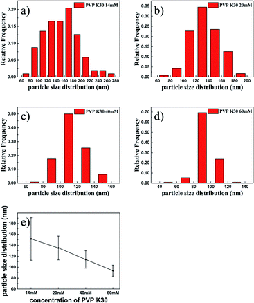
Fig. 1 shows the morphologies of PPy NPs prepared with different concentrations of PVP K30 in water using FeCl3 (280 mM) as the oxidizing agent. As shown in Fig. 1a and b, PPy tended to agglomerate at a low concentration of PVP during chemical oxidative polymerization by FeCl3. The as-prepared agglomerate PPy cannot be broken by sonication or vigorous magnetic stirring, although several particles were observed in Fig. 1a and b. The agglomeration problem was alleviated by using more PVP in the polymerization solutions (Fig. 1c–f). Besides, as shown in the inset images of Fig. 1, agglomerate polymers (Fig. 1a and b) could not form stable suspension in ethanol. However, PPy NPs synthesized with 60 mM PVP K30 could suspend in ethanol for more than 3 days. To calculate the particle sizes, about 100 particles were randomly chosen to calculate average diameters and error distributions, which are shown in Fig. 2. Fig. 2a–d showed that the average sizes of particles decreased from 151.5 nm to 93.5 nm with the increasing use of PVP. Moreover, higher PVP concentrations contributed to more homogeneous particles with smaller error values as shown in Fig. 2e. Thus, smaller diameters and narrower dispersity of PPy NPs were obtained with a higher concentration of PVP K30.
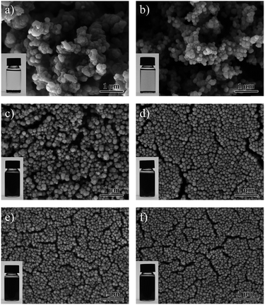 | ||
| Fig. 1 SEM images of the PPy NPs synthesized with PVP K30 concentrations of (a) 2 mmol L−1, (b) 8 mmol L−1, (c) 14 mmol L−1, (d) 20 mmol L−1, (e) 40 mmol L−1, and (f) 60 mmol L−1. | ||
Besides the investigation of PVP concentrations on particle sizes and distributions, the influence of molecular weights (or chain lengths) on the formation of PPy NPs was studied. Four types of PVPs with different molecular weights of 10![[thin space (1/6-em)]](https://www.rsc.org/images/entities/char_2009.gif) 000, 58
000, 58![[thin space (1/6-em)]](https://www.rsc.org/images/entities/char_2009.gif) 000, 360
000, 360![[thin space (1/6-em)]](https://www.rsc.org/images/entities/char_2009.gif) 000 and 1
000 and 1![[thin space (1/6-em)]](https://www.rsc.org/images/entities/char_2009.gif) 300
300![[thin space (1/6-em)]](https://www.rsc.org/images/entities/char_2009.gif) 000 were chosen for investigation. Results are shown in Fig. 3. Fig. 3a shows the morphology of PPy NPs prepared under the condition of the PPy with a molecular weight of 10
000 were chosen for investigation. Results are shown in Fig. 3. Fig. 3a shows the morphology of PPy NPs prepared under the condition of the PPy with a molecular weight of 10![[thin space (1/6-em)]](https://www.rsc.org/images/entities/char_2009.gif) 000. The NPs synthesized at this condition could not disperse well in ethanol. However, the PPy NPs synthesized by long chain PVPs showed much better stability, as displayed in Fig. 3b–d. The average diameters of PPy NPs stabilized with PVP K30, PVP K60 and PVP K90 were 134.9 nm, 97.9 nm and 86.8 nm, respectively. Although small particles could be obtained using the assistance of PVP K90 (molecular weight of 1
000. The NPs synthesized at this condition could not disperse well in ethanol. However, the PPy NPs synthesized by long chain PVPs showed much better stability, as displayed in Fig. 3b–d. The average diameters of PPy NPs stabilized with PVP K30, PVP K60 and PVP K90 were 134.9 nm, 97.9 nm and 86.8 nm, respectively. Although small particles could be obtained using the assistance of PVP K90 (molecular weight of 1![[thin space (1/6-em)]](https://www.rsc.org/images/entities/char_2009.gif) 300
300![[thin space (1/6-em)]](https://www.rsc.org/images/entities/char_2009.gif) 000), PVP K90 needs much longer time to dissolve in water than other PVPs with smaller molecular weights. Moreover, the PPy NPs covered with PVP K90 were very difficult to precipitate even after being centrifuged at the speed of 8000 rpm for one hour. Therefore, PVP K30 with the molecular weight of 58
000), PVP K90 needs much longer time to dissolve in water than other PVPs with smaller molecular weights. Moreover, the PPy NPs covered with PVP K90 were very difficult to precipitate even after being centrifuged at the speed of 8000 rpm for one hour. Therefore, PVP K30 with the molecular weight of 58![[thin space (1/6-em)]](https://www.rsc.org/images/entities/char_2009.gif) 000 is more suitable for industrial manufacture.
000 is more suitable for industrial manufacture.
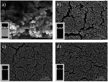 | ||
Fig. 3 SEM images of the PPy NPs synthesized using PVPs as the surfactants (60 mM) with different molecular weights of (a) Mw10![[thin space (1/6-em)]](https://www.rsc.org/images/entities/char_2009.gif) 000, (b) Mw58 000, (b) Mw58![[thin space (1/6-em)]](https://www.rsc.org/images/entities/char_2009.gif) 000, (c) Mw360 000, (c) Mw360![[thin space (1/6-em)]](https://www.rsc.org/images/entities/char_2009.gif) 000, (d) Mw 1 000, (d) Mw 1![[thin space (1/6-em)]](https://www.rsc.org/images/entities/char_2009.gif) 300 300![[thin space (1/6-em)]](https://www.rsc.org/images/entities/char_2009.gif) 000. 000. | ||
Although particles prepared in water can have reasonable dispersity with sizes as small as 86.8 ± 11.8 nm, we found that some particles tended to form large aggregations as shown in the inset image of Fig. S2a.† The rate of aggregations (the percentage of the aggregative PPy particles in the total particles) can be counted as high as 31.9% (Fig. S2†), which is harmful to disperse the PPy NPs into the ECAs uniformly. To prepare well-dispersed particles, different conditions with mixtures of ethanol and water at various ratios as co-solvents were investigated (all of the reactants are soluble to ethanol). Compared with synthesizing PPy NPs without ethanol (Fig. 4a), when the volume ratio of ethanol was set at 20%, the aggregation percentage decreased from 31.9% to 4.8% as shown in Fig. 4b. The synthesis of uniform and well-dispersed NPs may be resulting from adjusting the polarity of solution and a better solubility of pyrrole monomer and PVP in ethanol. On the other hand, the diameters of a few particles were also measured in their suspension states in water by using dynamic light scattering (DLS). The results obtained from SEM and DLS are very consistent (Fig. S3†).
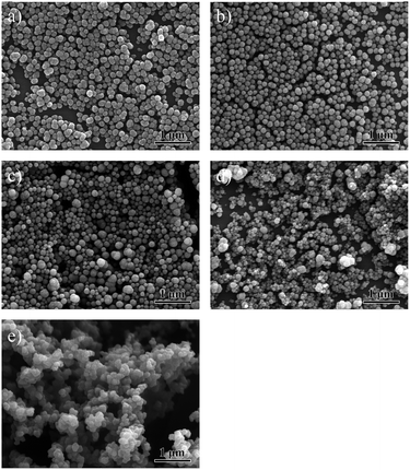 | ||
Fig. 4 SEM images of the PPy NPs synthesized in solutions (PVP K30 60 mM) with different ratios of ethanol to water. (a) Without ethanol, (b) 20%![[thin space (1/6-em)]](https://www.rsc.org/images/entities/char_2009.gif) : :![[thin space (1/6-em)]](https://www.rsc.org/images/entities/char_2009.gif) 80%, (c) 40% 80%, (c) 40%![[thin space (1/6-em)]](https://www.rsc.org/images/entities/char_2009.gif) : :![[thin space (1/6-em)]](https://www.rsc.org/images/entities/char_2009.gif) 60%, (d) 60% 60%, (d) 60%![[thin space (1/6-em)]](https://www.rsc.org/images/entities/char_2009.gif) : :![[thin space (1/6-em)]](https://www.rsc.org/images/entities/char_2009.gif) 40%, and (e) 80% 40%, and (e) 80%![[thin space (1/6-em)]](https://www.rsc.org/images/entities/char_2009.gif) : :![[thin space (1/6-em)]](https://www.rsc.org/images/entities/char_2009.gif) 20%. 20%. | ||
Furthermore, the rate of aggregation increased again to 9.3% with 40% ethanol. Moreover, a large amount of ethanol would also cause a deterioration of dispersity. Many large particles with diameters more than 300 nm co-existed with small particles when the solvents contained 40% and 60% ethanol, resulting in the non-uniform particles distributions (Fig. 4c and d). Statistical data analyses about the rate of aggregation of PPy particles accounting for total particles are shown in Fig. S2, S4 and S5† (corresponding to Fig. 4a–c in the paper, respectively).
Therefore, we concluded that increasing the quantity of PVPs, avoiding the choice of short chain PVPs, and adding suitable amount of ethanol were critical for obtaining PPy NPs with small sizes and excellent dispersity.
3.2 Electrical properties of ECAs
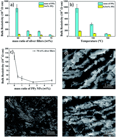
Before the ECAs studies, we characterized the silver flakes used for this research. Fig. S6 in the ESI† displays the XRD pattern and SEM images of the purchased silver flakes. As shown in Fig. S6b and c,† the diffraction peaks of the XRD pattern correspond to {111}, {200}, {220} and {311} planes of the face-centered cubic silver, and the silver flakes are around 150 nm thick. ECAs were prepared by doping the silver flakes into E51 epoxy resin with a curing agent of MeHHPA and a catalyst of DMP-30 by tuning their ratios. After mixing, the mixtures need to be cured to form the films of ECAs. Fig. S7 in the ESI† shows the DSC analysis of the curing process of the resin matrix. The curing process starts at about 100 °C, and curing speed reaches the peak at 137.5 °C. Thus, we normally use temperatures from 120 °C to 180 °C to cure the resin for solidification.The blue histograms in Fig. 5a showed the resistivity of the ECAs with different silver fillers curing at 160 °C without adding PPy NPs. It was observed that bulk resistivity decreased from 799.8 × 10⁻⁵ Ω cm for 60 wt% silver-filled ECAs to 47.1 × 10⁻⁵ Ω cm for 75 wt% silver-filled ECAs. Significant decrease of in resistivity was observed between ECAs with 60 wt% and 65 wt% silver flakes, indicating a percolation threshold of 65 wt% of silver flakes in this system. Some studies also reported similar phenomenon at the same curing temperature and curing time.12,18 Only when enough dosage (higher than the percolation threshold) of silver fillers was added into epoxy matrices, ECAs became obviously electrically conductive.11
It is important to note that after a small amount of PPy NPs (1 wt%) was filled into 60 wt% silver-filled ECAs, the bulk resistivity had a sharp decrease compared with that without PPy NPs, which decreased from 799.8 × 10⁻⁵ Ω cm to 61.4 × 10⁻⁵ Ω cm. Similar phenomenon was observed for other ECAs with various silver fillers, as shown by the comparison of the blue histograms and yellow histograms in Fig. 5a. The significant decrease in the resistivity by doping PPy NPs at 60 wt% of silver fillers shows the critical roles of improving conductivity by the PPy NPs. Thus, the ECAs with 1 wt% of PPy NPs in the 60 wt% silver flakes reached the same resistivity level as that of the ECAs with 75 wt% silver flakes. Such a system with a low weight percentage of silver, although possessing reasonably low resistivity, might be beneficial to reducing the cost and enhancing the flexibility of ECAs.
We also studied the roles of curing temperatures on resistivity. For this study, we chose the ECAs with 65 wt% silver flakes doped with 0.3 wt% of PPy NPs as a representative system. Results are plotted in Fig. 5b. It was found that even a very small amount of PPy NPs could reduce the resistivity significantly. Although using higher curing temperature could also bring about lower electrical resistivity (from 959.7 × 10⁻⁵ Ω cm to 89.7 × 10⁻⁵ Ω cm when curing temperature increased from 120 °C to 180 °C) without PPy NPs, higher curing temperature is harsh for temperature-sensitive devices. We have found that adding only a tiny amount of PPy NPs can reduce the resistivity significantly to achieve high conductive ECAs even by using a low curing temperature. For example, the electrical resistivity of 65 wt% silver-filled ECAs with 0.3 wt% PPy NPs cured at 120 °C (179.4 × 10⁻⁵ Ω cm) was much lower than that of the 65 wt% silver-filled ECAs without PPy NPs cured at 150 °C (412.2 × 10⁻⁵ Ω cm) (Fig. 5b). Furthermore, no obvious cracks in the ECAs PPy mixtures were observed even when heated at 180 °C for one hour (Fig. S8†), suggesting excellent stability for high temperature curing.
The doping amounts of PPy NPs in ECAs were also studied using 70 wt% of silver flakes cured at 160 °C for 60 min (Fig. 5c). Similar to the above investigation, doping the PPy NPs into the ECAs with as small as 0.46 wt% could significantly reduce the resistivity. When the PPy NPs reached 2.5 wt%, the lowest resistivity (9.3 × 10⁻⁵ Ω cm) was observed. With further increasing PPy NPs, the resistivity of ECAs increased slightly. Obviously, too many PPy NPs are harmful for electrical conductivity. This is because the PPy NPs belong to semiconducting materials, which have less conductivity than silver flakes. Reasonable PPy NPs can increase the epoxy matrix electric conductivity. A few research papers also reported the use of other nanomaterials as dopants in ECAs and found similar phenomena. For example, Oh et al. reported the use of 2 wt% carbon nanotubes in 80 wt% silver fillers-containing ECAs to achieve 1.84 × 10⁻⁵ Ω cm resistivity;40 Liu et al. reported the use of 0.05 wt% of graphene in 80 wt% silver fillers-containing ECAs to achieve 4.3 × 10⁻⁵ Ω cm resistivity;22 Zhang et al. used 76 wt% of silver nano-wire as the fillers to achieve 7.1 × 10⁻⁴ Ω cm resistivity.41 We have used much less weight percentage of silver fillers (70 wt%) with 2.5 wt% of PPy NPs to achieve 9.3 × 10⁻⁵ Ω cm resistivity (Fig. 5c), which is comparable to or even better than some nanomaterials-containing ECAs. Thus, our approach provides a new alternative strategy for preparing high-performance ECAs with fewer silver-flakes-filling and lower curing temperature.
SEM images gave the morphologies of the dispersion of silver flakes (Fig. 5d) and the PPy NPs doped in the 70 wt% silver flakes-containing ECAs (Fig. 5e and f). Fig. 5e and f showed that PPy NPs dispersed homogeneously in the E51 resin matrix and interspersed on the surface of silver flakes. PPy NPs as inherently conductive polymers filled into the gaps between silver flakes, which offered more conductive tracks to decrease the electrical resistance.
Furthermore, we performed two weeks aging experiments at 85 °C and 120 °C to test the time-dependent resistivity changes (Fig. S9†). The results (Fig. S9†) were obtained by averaging 9 measurements from different areas of each tested sample. For samples annealed at 85 °C, the bulk resistivity decreased in the first day and remained stable later. For samples annealed at 120 °C, the bulk resistivity decreased continuously during the aging process. In addition, annealing at higher temperature (herein, 120 °C) close to Tg of the adhesive resin (about 140 °C, not shown) might result in the silver flakes becoming much closer to increase the electrical conductivity. Much lower resistivity of the samples with PPy NPs than those without PPy during the two weeks aging was observed, showing that the PPy NPs played critical roles in decreasing bulk resistivity of ECAs.
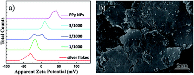
For further understanding the possible reasons of why a small percentage of semiconducting nanomaterials is used as dopants to increase the conductivity significantly, besides using SEM to observe the homogeneous dispersion of the nanoparticles in ECAs and the particles filled into the gaps between silver flakes (Fig. 5d and f), we further used zeta potentials to see other possible reasons. It was found that a larger absolute value of zeta potential reflects that there are more positive charges or negative charges on the surface of suspended solids, which can stabilize powders in the environment.42–44 The zeta potential of silver flakes (0.2 g L−1) suspended in water was measured to be −35.6 mV, while the zeta potential of PPy NPs is +37.7 mV (Fig. 6a). The zeta potentials of the mixtures were found to be between +37.7 mV and −35.6 mV. Typical measurement data of the mixtures with the mass ratios of PPy NPs to silver flakes of 1/1000, 2/1000 and 3/1000 were found to be −18.5 mV, −11.5 mV and 9.7 mV, as plotted in Fig. 6a. The negatively charged silver flakes had strong interactions with positively charged PPy NPs, which resulted in adsorption of PPy NPs on the surface of silver flakes (Fig. 6b). This might reduce the electrostatic repulsions between the silver flakes to achieve higher electric conductivity than those of free silver flakes in the matrices.
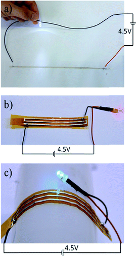
With the above understanding, we printed one type of ECA with 0.5 wt% PPy NPs (samples shown in Fig. 4b) doped in 65 wt% silver-flakes-containing E51 resin on white paper (Fig. 7a) and flexible polyimide substrates (Fig. 7b and c). These resins were cured at 140 °C for 30 minutes. Even under such a low temperature and short curing time, the printed electronics showed excellent conductivity to enable the lighting of the LED devices. Furthermore, since the circuits were printed on flexible substrates, LED could still be light under a bending condition.
4. Conclusions
In summary, a facile chemical oxidative polymerization method was used to synthesize well-dispersed polypyrrole nanoparticles (PPy NPs). The diameters of as-prepared PPy NPs could be manipulated from 151.5 nm to 86.8 nm by changing the concentrations of PVPs and the chain lengths of PVPs. Besides, a suitable amount of ethanol was beneficial to prepare well-dispersed PPy NPs. The electrical conductivity was obviously enhanced by adding a small amount of PPy NPs into traditional silver fillers-based ECAs, which provides a feasible strategy of saving the cost by reducing the use of silver in ECAs and enhancing the electrical conductivity at a low curing temperature. As a result, bulk resistivity can decrease to as low as 9.3 × 10⁻⁵ Ω cm when incorporating 2.5 wt% PPy NPs into 70 wt% silver-filled ECAs cured at 160 °C for 60 min. Finally, flexible paper-based and polyimide-based circuits were prepared to enable the lighting of LEDs using them. Due to the flexibility of these ECAs, the circuits could still maintain excellent conductivity after being folded.Conflicts of interest
There are no conflicts to declare.Acknowledgements
The authors are grateful for financial support from the National Natural Science Foundation of China (Grant No. 51522503) and the Program for New Century Excellent Talents in University (NCET-13-0175). This work was also supported partially by the start fund of SUSTech (Y01256009).Notes and references
- Directive 2002/96/EC of the European Parliament and of the Council on Waste Electrical and Electronic Equipment (WEEE), Report 46(L 37), Official Journal of the European Union, 2003.
- Directive 2002/95/EC of the European Parliament and of the Council of 27 January 2003 on the Restriction of the Use of Certain Hazardous Substances in Electrical and Electronic Equipment., Report 46(L 37), Official Journal of the European Union, 2003.
- H. W. Cui, J. T. Jiu, S. Nagao, T. Sugahara, K. Suganuma, H. Uchida and K. A. Schroder, RSC Adv., 2014, 4, 15914–15922 RSC.
- D. D. Chang, P. A. Crawford, J. A. Fulton, R. Mcbride, M. B. Schmidt, R. E. Sinitski and C. P. Wong, IEEE Trans. Compon., Hybrids, Manuf. Technol., 1993, 16, 828–835 CrossRef CAS.
- Y. Li and C. P. Wong, Mat. Sci. Eng. R., 2006, 51, 1–35 CrossRef.
- I. Mir and D. Kumar, Int. J. Adhes. Adhes., 2008, 28, 362–371 CrossRef CAS.
- H. M. Ren, Y. Guo, S. Y. Huang, K. Zhang, M. M. Yuen, X. Z. Fu, S. Yu, R. Sun and C. P. Wong, ACS Appl. Mater. Interfaces, 2015, 7, 13685–13692 CAS.
- B. Yao, J. Zhang, T. Kou, Y. Song, T. Liu and Y. Li, Adv. Sci., 2017, 4, 1700107 CrossRef PubMed.
- Z. Li, T. R. Le, Z. Wu, Y. G. Yao, L. Y. Li, M. Tentzeris, K. S. Moon and C. P. Wong, Adv. Funct. Mater., 2015, 25, 464–470 CrossRef CAS.
- C. Yang, X. Cui, Z. Zhang, S. W. Chiang, W. Lin, H. Duan, J. Li, F. Kang and C. P. Wong, Nat. Commun., 2015, 6, 8150 CrossRef PubMed.
- G. R. Ruschau, S. Yoshikawa and R. E. Newnham, J. Appl. Phys., 1992, 72, 953–959 CrossRef CAS.
- J. Luo, Z. J. Cheng, C. W. Li, L. J. Wang, C. P. Yu, Y. Zhao, M. H. Chen, Q. W. Li and Y. G. Yao, Compos. Sci. Technol., 2016, 129, 191–197 CrossRef CAS.
- S. F. Sun, Z. H. Pan, W. Zhang, F. K. Yang, Y. D. Huang and B. X. Zhao, J. Mater. Sci.: Mater. Electron., 2016, 27, 4363–4371 CrossRef CAS.
- L. Wang, C. Wan, Y. G. Fu, H. T. Chen, X. J. Liu and M. Y. Li, J. Electron. Mater., 2014, 43, 132–136 CrossRef CAS.
- L.-N. Ho, T. F. Wu and H. Nishikawa, J. Adhes., 2013, 89, 847–858 CrossRef CAS.
- X. Li, B. Zheng, L. Xu, D. Wu, Z. Liu and H. Zhang, Rare. Metal. Mat. Eng., 2012, 41, 24–27 CrossRef CAS.
- F. Tan, X. Qiao, J. Chen and H. Wang, Int. J. Adhes. Adhes., 2006, 26, 406–413 CrossRef CAS.
- C. Yang, W. Lin, Z. Y. Li, R. W. Zhang, H. R. Wen, B. Gao, G. H. Chen, P. Gao, M. M. F. Yuen and C. P. Wong, Adv. Funct. Mater., 2011, 21, 4582–4588 CrossRef CAS.
- C. W. Li, X. K. Gong, L. Tang, K. Zhang, J. Luo, L. Ling, J. Pu, T. T. Li, M. X. Li and Y. G. Yao, J. Mater. Chem. C, 2015, 3, 6178–6184 RSC.
- B. M. Amoli, S. Gumfekar, A. M. Hu, Y. N. Zhou and B. X. Zhao, J. Mater. Chem., 2012, 22, 20048–20056 RSC.
- V. H. Luan, H. N. Tien, T. V. Cuong, B.-S. Kong, J. S. Chung, E. J. Kim and S. H. Hur, J. Mater. Chem., 2012, 22, 8649–8653 RSC.
- K. Liu, L. Liu, Y. Luo and D. Jia, J. Mater. Chem., 2012, 22, 20342–20352 RSC.
- H. W. Cui, A. Kowalczyk, D. S. Li and Q. Fan, Int. J. Adhes. Adhes., 2013, 44, 220–225 CrossRef CAS.
- R. Ma, S. Kwon, Q. Zheng, H. Y. Kwon, J. I. Kim, H. R. Choi and S. Baik, Adv. Mater., 2012, 24, 3344 CrossRef CAS PubMed.
- P. Peng, A. M. Hu, H. Huang, A. P. Gerlich, B. X. Zhao and Y. N. Zhou, J. Mater. Chem., 2012, 22, 12997–13001 RSC.
- R. Zhang, W. Lin, K. S. Moon and C. P. Wong, ACS Appl. Mater. Interfaces, 2010, 2, 2637–2645 CAS.
- Z. X. Zhang, X. Y. Chen and F. Xiao, J. Adhes. Sci. Technol., 2011, 25, 1465–1480 CrossRef CAS.
- R. C. Advincula, J. Am. Chem. Soc., 2011, 133, 5622 CrossRef CAS.
- Y.-J. Cheng, S.-H. Yang and C.-S. Hsu, Chem. Rev., 2009, 109, 5868–5923 CrossRef CAS PubMed.
- T. K. Das and S. Prusty, Polym-Plast. Technol., 2012, 51, 1487–1500 CrossRef CAS.
- E. Armelin, R. Pla, F. Liesa, X. Ramis, J. I. Iribarren and C. Aleman, Corros. Sci., 2008, 50, 721–728 CrossRef CAS.
- D. Kowalski, M. Ueda and T. Ohtsuka, Corros. Sci., 2007, 49, 1635–1644 CrossRef CAS.
- A. Sakhri, F. X. Perrin, E. Aragon, S. Lamouric and A. Benaboura, Corros. Sci., 2010, 52, 901–909 CrossRef CAS.
- Z. Liu, Y. Su and K. Varahramyan, Thin Solid Films, 2005, 478, 275–279 CrossRef CAS.
- J. Lee, P. Lee, H. B. Lee, S. Hong, I. Lee, J. Yeo, S. S. Lee, T.-S. Kim, D. Lee and S. H. Ko, Adv. Funct. Mater., 2013, 23, 4171–4176 CrossRef CAS.
- J. Pecher and S. Mecking, Chem. Rev., 2010, 110, 6260–6279 CrossRef CAS PubMed.
- D. Tuncel and H. V. Demir, Nanoscale, 2010, 2, 484–494 RSC.
- M. Aldissi and S. P. Armes, Prog. Org. Coat., 1991, 19, 21–58 CrossRef CAS.
- M. Tsuji, Y. Nishizawa, K. Matsumoto, M. Kubokawa, N. Miyamae and T. Tsuji, Mater. Lett., 2006, 60, 834–838 CrossRef CAS.
- Y. Oh, D. Suh, Y. Kim, E. Lee, J. S. Mok, J. Choi and S. Baik, Nanotechnology, 2008, 19, 495602 CrossRef PubMed.
- Z. Zhang, X. Chen, H. Yang, H. Fu and F. Xiao, presented in part at the ICEPT-HDP, Beijing, China, 2009 Search PubMed.
- N. Sakthivel, R. Socrates, G. M. Shanthini, A. Rajaram and S. N. Kalkura, Mater. Sci. Eng., C, 2015, 47, 222–229 CrossRef CAS PubMed.
- S. Singh, A. Bharti and V. K. Meena, J. Mater. Sci.: Mater. Electron., 2014, 25, 3747–3752 CrossRef CAS.
- Y.-S. Wang, J.-H. Shen, J.-P. Lin and J.-J. Horng, J. Therm. Anal. Calorim., 2013, 111, 1443–1448 CrossRef CAS.
Footnote |
| † Electronic supplementary information (ESI) available: XRD of silver flakes and SEM images of PPy nanoparticles. See DOI: 10.1039/c7ra09725e |
| This journal is © The Royal Society of Chemistry 2017 |

