 Open Access Article
Creative Commons Attribution 3.0 Unported Licence
High-pressure salt templating strategy toward intact isochoric hierarchically porous carbon monoliths from ionic liquids
Zhen Zhang,
Junzong Feng,
Yonggang Jiang and
Jian Feng *
*
Science and Technology on Advanced Ceramic Fibers and Composites Laboratory, National University of Defense Technology, 109 De Ya Rd, Changsha, Hunan 410073, China. E-mail: fengj@nudt.edu.cn; Fax: +86 073184576578; Tel: +86 073184576291
First published on 2nd November 2017
Abstract
Through a facile and novel high-pressure salt templating approach, a crack-free hierarchically porous carbon monolith without visible volume changes was prepared using 1-ethyl-3-methyl-imidazolium dicyanamide (Emim-dca) as a carbon precursor. TG-DSC and FT-IR measurements revealed that Emim-dca pyrolysis, decomposition, crosslinking and carbonization reactions occurred in turn at temperatures of 234–350 °C, 350–520 °C and 520–1000 °C, respectively, which provides a guide for the preparation of an intact porous carbon monolith. The porous carbon monolith prepared at 4 MPa is amorphous and composed of small, uniform carbon particles with interconnected interstitial pores. Its bulk density is 0.072 g cm−3. Besides the advantages of well monolithic formability and integrity derived from high pressure strategy, interestingly, the obtained porous carbon monolith possesses a higher specific surface area compared to the porous carbon powders fabricated through ambient pressure salt templating. The meso and macro specific surface area of the resultant porous carbon monolith is nearly three times higher (314.0 versus 106.7 m2 g−1) with the content of 4 nm mesopore increasing dramatically compared to that of porous carbon powders prepared under ambient pressure, while the architecture of micropores keeps unchanged. These results might be explained as follows. The high pressure compresses gas molecules from the decomposition reaction into the carbon skeleton to form super-mesopores and macropores and simultaneously disperses salt clusters, generating small (∼4 nm) mesopores. As a solution to volume expansion in powders obtained via salt templating, the high pressure results in a porous carbon with an intact monolithic shape without volume expansion or shrinkage. Thus, fiber-reinforced porous carbon composites can be prepared for ultra-high-temperature insulation using the high-pressure salt templating method.
Introduction
Porous carbons are attracting more and more interest due to their biocompatibility, chemical stability in inert or vacuum atmospheres, low cost, extensive accessibility, low density, high porosity, ultra-high temperature resistance (up to 2000 °C under inert atmosphere or vacuum), low thermal conductivity at high temperature (ascribed to outstanding adsorption for infrared radiation) and so on.1–3 Porous carbons have already been extensively applied in the fields of separation, purification, catalysts and catalyst supports, supercapacitors, electrochemical electrodes, sensors and thermal insulation.2–19 Porous carbons can be prepared in the form of fibers, membranes, capsules, powders and monoliths.4 Among these porous carbons with different shapes, porous carbon monoliths are of vital importance because they have promising applications in fields involving catalyst carriers, thermal and acoustic insulation, adsorption of volatile organic pollutants in the air, hydrogen storage, and sewage disposal, where porous carbon monoliths are functionally advantageous.5–19 Moreover, the freestanding ability of porous carbon monoliths makes their handling easy and simple. Porous carbon monoliths can be conventionally obtained through sol–gel, solvothermal–pyrolysis, activation and template methods.11–25 For example, resorcinol and formaldehyde, furfuryl alcohol and lignin have been used as carbon precursors to prepare hierarchical carbon monoliths via inorganic hard-template methods. Chunfeng Xue et al. fabricated highly nitrogen-doped porous carbon monoliths through a zeolite cage-lock method to directly pyrolyze ZSM-39. In 2011, monolithic mesoporous nitrogen-doped carbons were prepared through an incipient wetness strategy for hydrogen storage. The porous carbons with hierarchical pore structures synthesized through sol–gel methodology exhibited excellent ultra-high temperature insulation and CO2 capture properties. The solvothermal–pyrolysis process as a low-cost and energy-saving method that can be applied to fabricate porous carbon monoliths with very good integrity.11–24 However, the microstructures of porous carbon monoliths prepared through the activation approach are not uniform and interconnected; the template method is complex, cumbersome and time-consuming; the specific surface areas of porous carbon monoliths prepared by the solvothermal–pyrolysis process are relatively low; and the sol–gel method has shortcomings including large volume shrinkage, resulting in cracks and deformations in the carbonization process.2,3,11–24 So it is critical to develop other methodologies to fabricate porous carbon monoliths.Ionic liquids are increasing being used as carbon precursors to prepare heterofunctional porous carbons because they are liquid at room temperature, have negligible vapor pressure and naturally contain heteroatoms.25–27 In 2006, the salt templating method was invented as a simple and sustainable pathway to fabricate hierarchically porous carbons.28 Recently, Markus Antonietti et al. used ionic liquids as carbon precursors and simultaneously adopted the salt templating method to prepare porous functional carbons for the first time.29 In follow-up studies, microporous carbon powders with high specific surface areas of up to 2830 m2 g−1 (close to the theoretical specific surface area of graphene, 2965 m2 g−1) were prepared via the condensation of ionic liquids within salt eutectics, and poly(ionic liquid)s were developed to prepare porous carbon fibers and membranes due to their processability as polymers.4,30 Additionally, metal-free N-doped carbon aerogels as promising electrocatalytic materials and high surface area iron/cobalt-containing N-doped porous carbon aerogels for oxygen reduction reaction were prepared using ionic liquids via the salt templating method.31–33 By researching the effects of different ionic liquids and salts on the porous carbons, it was verified that the alkaline earth metal salts can be used as porogens to fabricate micropores and mesopores by tuning the concentrations of salts due to their small molecular size. Zinc salts with large grain size can build up the entire mesoporous architecture, even at low concentrations. Moreover, the nature of ionic liquids plays a minor role in the structure of the porous carbon, while the yield of the porous carbon material mainly depends on the type of ionic liquid.29,30,34,35 In 2016, Shu-Hong Yu and Markus Antonietti et al. prepared robust monolithic carbon aerogels through the direct carbonization of phenol-formaldehyde polymer under the hypersaline conditions of ZnCl2 salts.36 There is no doubt that scholars are paying more and more attention to the salt templating method to prepare porous carbons. However, because salts serve as dehydration and foaming agents in the salt templating method in addition to porogens, uncontrollable and large volume expansions ascribed to foaming inevitably occur during the carbonization process, resulting in material deformation and cracking. According to the literature,28–36 the resulting porous carbons expand to several times their original volumes, and, in most cases, only porous carbon powders can be obtained. Thus, it is a pressing challenge to prepare crack-free isochoric porous carbon monoliths with good integrity using ionic liquids via the salt templating method.
In the salt templating method, the foaming phenomenon makes it difficult to fabricate intact porous carbon monoliths with desired geometries. To the best of our knowledge, no reports have solved the problem of uncontrollable volume expansion. To address this problem, TG-DSC and FT-IR analyses were applied to determine the reason for the foaming phenomenon and the accurate reaction mechanism for the pyrolysis of Emim-dca. The salt templating method was conducted under high-pressure in inert atmosphere to prevent foaming, resulting in intact, crack-free and isochoric porous carbon monoliths. In addition, the obtained porous carbon monolith was characterized to analyze the porous and crystalline structures via nitrogen adsorption, scanning electron microscopy and X-ray diffraction measurements. Due to the high porosity and great monolithic integrity of the resulting monolith, the high-pressure salt templating method is promising for the preparation of fiber-reinforced porous carbon composites for use in the ultra-high-temperature insulation field.
Results and discussion
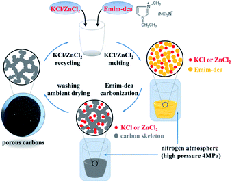
A schematic of the preparation of porous carbon monoliths via the high-pressure salt templating method under nitrogen atmosphere is shown in Fig. 1. Briefly, KCl and ZnCl2 as porogens as well as 1-ethyl-3-methyl-imidazolium dicyanamide as a carbon precursor were mixed thoroughly. Under the protection of a high-pressure (4 MPa) nitrogen atmosphere, the mixtures were subsequently heated to 700 °C at a heating rate of 2 °C min−1 and remained at 700 °C for 1 h. The entire thermal treatment was conducted under the high-pressure nitrogen atmosphere. After washing several times with water, a dry porous carbon monolith was obtained by drying in an oven at ambient pressure.To study the effects of pressure on porous carbons, experiments were carried out under vacuum and under a nitrogen atmosphere at ambient pressure with the same process used to prepare the porous carbon monolith. To determine the exact reaction mechanism for the pyrolysis of Emim-dca, pure Emim-dca was pyrolyzed under nitrogen atmosphere at ambient pressure using the same thermal treatment procedure used to prepare the porous carbon monolith. Eight samples were analyzed at temperatures from 300 °C to 1000 °C using TG-DSC and FT-IR.
Reaction mechanism for the pyrolysis of Emim-dca
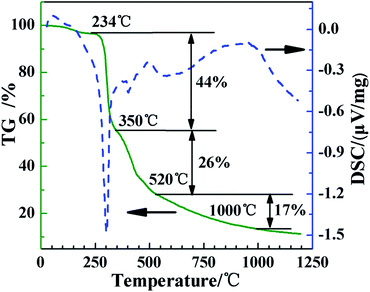
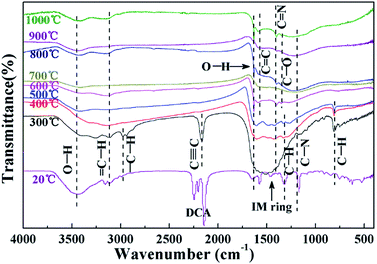
Fig. 2 shows the TG and DSC traces of Emim-dca. There are three main stages of thermal weight loss in the process of pyrolyzing Emim-dca under nitrogen atmosphere. Emim-dca is stable until 234 °C, and the slight weight loss before 234 °C corresponds to the evaporation of physically and chemically adsorbed H2O. The first stage of rapid weight loss occurs between 234 °C and 350 °C, and the percentage of weight loss is 44%. This large mass loss should be attributed to the generation and emission of numerous gas molecules resulting from decomposition reactions. The second stage of weight loss occurs from 350 °C to 520 °C, and the percentage of mass loss is 26%. The third stage of weight loss occurs after 520 °C, and the percentage of weight loss in this stage is only 17% at 1000 °C. The carbonization reaction tends to be slow and mild after 520 °C. At 1000 °C, the total mass loss is 87% (i.e., the percentage of residual carbon is 13%). In the DSC trace, the sharp exothermic peak between 234 °C and 350 °C indicates a large rate of weight loss and an extremely violent reaction, which would lead to the formation of cracks and powders. Therefore, to obtain a crack-free, porous carbon monolith without volume changes, the heating rate between 234 °C and 350 °C should be slow so that the reaction process is less violent.The FT-IR spectra of Emim-dca and its pyrolyzed products at different temperatures are shown in Fig. 3. According to past studies,37–39 the peaks between 2100 and 2300 cm−1 represent the vibration of dicyanamide, and the peaks from 1300 to 1600 cm−1 reflect the plane vibration of the imidazole ring. Considering the other typical peaks, the FT-IR spectrum of Emim-dca at 20 °C demonstrates that the ionic liquid used was standard Emim-dca with a little H2O, which was confirmed by TG-DSC measurement. The peaks around 3430 and 1630 cm−1 in every spectrum are ascribed to hydroxyl groups, and the peaks at 1300 cm−1 correspond to the vibration of C–O bonds. These peaks demonstrate the presence of H2O or hydroxyl bonding, which is attributed to the oxidation of a small amount of residual O2 during the pyrolysis of Emim-dca. The adsorption peak at 2190 cm−1 represents the characteristic vibration of C![[triple bond, length as m-dash]](https://www.rsc.org/images/entities/char_e002.gif) C bonds, and the peaks at 1580 and 1420 cm−1 are related to the presence of C
C bonds, and the peaks at 1580 and 1420 cm−1 are related to the presence of C![[double bond, length as m-dash]](https://www.rsc.org/images/entities/char_e001.gif) C and C
C and C![[double bond, length as m-dash]](https://www.rsc.org/images/entities/char_e001.gif) N bonds, respectively. When the temperature increases from 20 °C to 300 °C, the peaks related to C
N bonds, respectively. When the temperature increases from 20 °C to 300 °C, the peaks related to C![[triple bond, length as m-dash]](https://www.rsc.org/images/entities/char_e002.gif) N bonding and imidazole ring groups clearly disappear, and those related to C
N bonding and imidazole ring groups clearly disappear, and those related to C![[triple bond, length as m-dash]](https://www.rsc.org/images/entities/char_e002.gif) C and C
C and C![[double bond, length as m-dash]](https://www.rsc.org/images/entities/char_e001.gif) N bonding appear. This is attributed to the rupturing of the C
N bonding appear. This is attributed to the rupturing of the C![[triple bond, length as m-dash]](https://www.rsc.org/images/entities/char_e002.gif) N bonds and imidazole rings. Thus, it can be concluded that Emim-dca decomposes between 20 °C and 300 °C. In addition, the bands at around 3130, 2950, 1270 and 800 cm−1 are assigned to saturated and unsaturated C–H groups. The peaks representing the plane swing vibration of C–H bonds gradually become weak starting at 300 °C and vanish at 600 °C. Together with the disappearance of the peaks corresponding to C
N bonds and imidazole rings. Thus, it can be concluded that Emim-dca decomposes between 20 °C and 300 °C. In addition, the bands at around 3130, 2950, 1270 and 800 cm−1 are assigned to saturated and unsaturated C–H groups. The peaks representing the plane swing vibration of C–H bonds gradually become weak starting at 300 °C and vanish at 600 °C. Together with the disappearance of the peaks corresponding to C![[triple bond, length as m-dash]](https://www.rsc.org/images/entities/char_e002.gif) C bonds, this indicates that molecular rearrangement and thermal dehydrogenation polycondensation occur between 300 °C and 600 °C, and the molecules originating from the decomposition reaction crosslink to fabricate a solid carbon skeleton. As the temperature increases from 600 °C to 1000 °C, there are no visible changes in the FT-IR spectra except for the gradual increase in the degree of carbon unsaturation. Hence, it can be assumed that after 600 °C, the carbonization reaction continually intensifies to form microcrystalline graphitic carbons and a nanoporous interconnected structure of porous carbons, as confirmed in the subsequent XRD measurements.38–42
C bonds, this indicates that molecular rearrangement and thermal dehydrogenation polycondensation occur between 300 °C and 600 °C, and the molecules originating from the decomposition reaction crosslink to fabricate a solid carbon skeleton. As the temperature increases from 600 °C to 1000 °C, there are no visible changes in the FT-IR spectra except for the gradual increase in the degree of carbon unsaturation. Hence, it can be assumed that after 600 °C, the carbonization reaction continually intensifies to form microcrystalline graphitic carbons and a nanoporous interconnected structure of porous carbons, as confirmed in the subsequent XRD measurements.38–42
Based on the TG-DSC analysis of Emim-dca and the obtained FT-IR spectra, the reaction mechanism of Emim-dca pyrolysis can be accurately summarized. Because the C![[triple bond, length as m-dash]](https://www.rsc.org/images/entities/char_e002.gif) N bond and imidazole rings rupture, the decomposition reaction results in the generation and emission of many small gas molecules from 234 °C to 350 °C. Next, from 350 °C to 520 °C, molecular rearrangement and thermal dehydrogenation polycondensation cause the liquid molecules generated from the decomposition reaction to crosslink into a solid carbon skeleton. As the carbonization reaction intensifies, and the degree of carbon unsaturation increases, the carbon skeleton continuously carbonizes to form microcrystalline graphitic carbons and an interconnected nanostructure of porous carbons after 520 °C. Finally, to obtain crack-free, isochoric and intact porous carbon monoliths, it is necessary to slow the heating rate between 234 °C and 350 °C, when the decomposition reaction is violent.
N bond and imidazole rings rupture, the decomposition reaction results in the generation and emission of many small gas molecules from 234 °C to 350 °C. Next, from 350 °C to 520 °C, molecular rearrangement and thermal dehydrogenation polycondensation cause the liquid molecules generated from the decomposition reaction to crosslink into a solid carbon skeleton. As the carbonization reaction intensifies, and the degree of carbon unsaturation increases, the carbon skeleton continuously carbonizes to form microcrystalline graphitic carbons and an interconnected nanostructure of porous carbons after 520 °C. Finally, to obtain crack-free, isochoric and intact porous carbon monoliths, it is necessary to slow the heating rate between 234 °C and 350 °C, when the decomposition reaction is violent.
Characterization of porous carbons prepared under different pressures
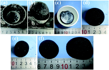
The photographs of porous carbons prepared under vacuum, ambient pressure (0.1 MPa) and high pressure (4 MPa) nitrogen atmospheres before and after washing with water are shown in Fig. 4. For all samples, it is clear that Emim-dca carbonized into a black material under non-oxidizing atmosphere at different pressures. The samples differ in yield and morphology. Under vacuum, porous carbons cannot be obtained because of reagent overflow. This occurs because the violent emission of excess gases from decomposition reaction and the foaming effect derived from salts together result in over-boiling phenomenon. Under ambient pressure (0.1 MPa), foaming results in a volume expansion of several times the initial volume, and the porous carbons obtained are fragile powders. Under high pressure (4 MPa), the foaming problem is effectively solved, and a porous carbon monolith is obtained. Fig. 4(d)–(f) show the morphology of the porous carbon monolith prepared under high pressure (4 MPa) after washing with water and drying at ambient pressure. The porous carbon monolith has no cracks, and no visible volume changes are observed in comparison with the original volume. The bulk density is 0.072 g cm−3. These results indicate that the foaming phenomenon during the decomposition process was relieved to a large extent. Moreover, the high pressure helped improve the monolithic integrity and retain the original volume and shape. Last but not least, if the porous carbon monoliths are used to prepare composites for some applications such as thermal insulation, the crack-free performance of them can ensure the excellent linkage between carbon monoliths as matrix with fibers as enforcement phase.The XRD patterns of the washed and dried porous carbons prepared under ambient pressure (0.1 MPa) and high pressure (4 MPa) indicate that the two samples are basically amorphous (Fig. 5). The two broad peaks in the diffraction patterns at about 2θ = 25° (002) and 2θ = 44° (100) correspond to slightly disordered graphitic carbon. This confirms the conclusion from FT-IR analysis that microcrystalline graphitic carbon formed through continuous carbonization reaction after 520 °C. The obvious small sharp peak in the XRD pattern of the porous carbon monolith prepared under high pressure (4 MPa) is attributed to the typical crystalline peak of Zn5(OH)8Cl2·H2O, which originates from the residue of the salt eutectic KCl/ZnCl2. The results suggest that the high pressure (4 MPa) had no effect on the amorphous structure of the porous carbon.
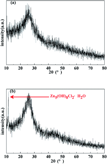 | ||
| Fig. 5 XRD patterns of porous carbons prepared under (a) ambient pressure (0.1 MPa) and (b) high pressure (4 MPa). | ||
The nitrogen sorption isotherms of the porous carbons prepared under ambient pressure (0.1 MPa) and high pressure (4 MPa) are shown in Fig. 6(a). The porous carbons prepared under ambient pressure (0.1 MPa) exhibit the features of IUPAC type-I and type-II sorption isotherms, indicating the presence of micropores and macropores.43 The strong gas adsorption in ultra-low relative pressure region (P/P0 ≤ 0.05) indicates the presence of micropores. In the middle and high relative pressure range, the slow increase of adsorption is ascribed to the single-layer and multi-layer adsorption of macropores. The nitrogen sorption isotherm of the porous carbon monolith prepared under high pressure (4 MPa) belongs to the type-IV sorption isotherm and reflects the presence of micropores, mesopores and macropores. Because the nitrogen uptake amount in the ultra-low relative pressure range is nearly the same as that for porous carbon powders prepared under ambient pressure (0.1 MPa), high pressure does not change the contribution of micropores. In the middle relative pressure range (0.4 ≤ P/P0 ≤ 0.8), a hysteresis loop appears, and the adsorption amount increases greatly. This can be ascribed to capillary condensation resulting from the increased contribution of mesopores. When the relative pressure is between 0.8 and 1, the adsorption amount increases sharply with adsorption unsaturation. Similarly, the content of small macropores in the structure of the porous carbon monolith prepared under high pressure (4 MPa) is greater than that of the porous carbon prepared under ambient pressure (0.1 MPa). Thus, it can be concluded that high pressure enhances the contributions of mesopores and macropores in the structure of the porous carbon monolith while having little effect on the micropores.
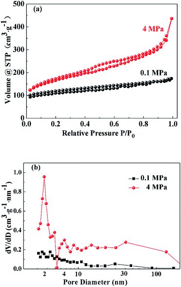 | ||
| Fig. 6 Nitrogen sorption isotherms (a) and BJH pore size distribution curves (b) of the porous carbons prepared under ambient pressure (0.1 MPa) and high pressure (4 MPa). | ||
Fig. 6(b) presents the BJH pore size distribution curves of the porous carbons prepared under ambient pressure (0.1 MPa) and high pressure (4 MPa). The BJH pore size distribution curve of the porous carbons prepared under ambient pressure (0.1 MPa) has no obvious peak. In addition, the contribution of small mesopores increases as mesopore size decreases; that is, micropores are dominant, and there are very few small macropores in the porous carbon powders. The BJH pore size distribution curve of the porous carbons prepared under high pressure (4 MPa) indicates a large increase in mesopores and macropores. The peak around 4 nm indicates that the contribution of mesopores with sizes of approximately 4 nm increases the most. One of the reasons could be that at high pressure, the gas molecules derived from decomposition reaction were compressed into carbon skeleton forming more super-mesopores and macropores instead of releasing into the air with the appearance of foaming phenomenon. Moreover, high pressure might help disperse salt clusters as porogens, further favoring the fabrication of small mesopores with sizes around 4 nm.
The exact values of the textural parameters of porous carbons derived under ambient pressure (0.1 MPa) and high pressure (4 MPa) are listed in Table 1. The BET specific surface area of the porous carbon monolith derived under high pressure (4 MPa) is higher than that of the porous carbon prepared under ambient pressure (0.1 MPa), and the meso and macro specific surface area is nearly three times higher. In contrast, the micro specific surface area remains at approximately 285 m2 g−1, and the micropore volume is 0.124 cm3 g−1. This illustrates that the high pressure (4 MPa) helps generate more mesopores and macropores, thereby increasing the specific surface area, but has little influence on the micropore architecture.
| Carbonization pressure (MPa) | BET specific surface area (m2 g−1) | Micro-pore volume (cm3 g−1) | Micro specific surface area (m2 g−1) | Meso and macro specific surface area (m2 g−1) |
|---|---|---|---|---|
| 0.1 | 403.108 | 0.124 | 296.375 | 106.733 |
| 4 | 591.776 | 0.124 | 277.780 | 313.996 |
From the nitrogen sorption analyses, it can be determined that high pressure (4 MPa) enhances the contributions of mesopores and macropores, vastly increasing the specific surface area, but has no effect on micropores. This may be because the high pressure compresses the gas molecules from the decomposition reaction into the carbon skeleton, leading to the formation of more super-mesopores and macropores during the crosslinking process. Furthermore, the high pressure also helps disperse the salt clusters as porogens more uniformly to fabricate more small mesopores with sizes of around 4 nm, which needs to be verified.
The scanning electron micrographs of the porous carbons prepared under ambient pressure (0.1 MPa) and high pressure (4 MPa) are shown in Fig. 7. The porous carbons formed under ambient pressure (0.1 MPa) possess a porous interconnected network composed of irregular carbon tectonic particles and interstitial pores. The pore sizes are large, and interstitial pores are fabricated because the amount of salt is sufficient to form a continuous phase. Comparatively, the structure of the porous carbon monolith prepared under high pressure (4 MPa) is uniform and homogeneous. Its porous interconnected network is composed of small carbon skeleton nanoparticles, and the pore sizes are relatively uniform and average. The uniform and regular structure and centralized pore size along with the small carbon skeleton particles are ascribed to the high pressure. This result supports the conclusions of the nitrogen sorption analyses to a certain extent.
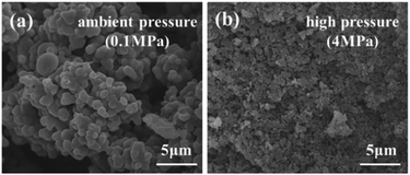 | ||
| Fig. 7 Scanning electron micrographs of porous carbons prepared under (a) ambient pressure (0.1 MPa) and (b) high pressure (4 MPa). | ||
In conclusion, porous carbons cannot be obtained under vacuum because of the violent decomposition reaction and foaming phenomenon resulting from salts, which inevitably result in the over-boiling and overflowing of reagents. Under ambient pressure (0.1 MPa), the obtained porous carbons are fragile powders because the foaming phenomenon leads to a volume expansion of several times the initial volume. By greatly relieving the foaming phenomenon, an intact, crack-free, isochoric and hierarchically porous carbon monolith with uniform microstructure was prepared under high pressure (4 MPa). We hypothesized that the high pressure compressed the gas molecules produced by the decomposition reaction into the carbon scaffolds to form more super-mesopores and macropores and dispersed the salt clusters to form more small (∼4 nm) mesopores while not affecting the micropore structure.
Conclusions
In the pyrolysis of Emim-dca, intramolecular C![[triple bond, length as m-dash]](https://www.rsc.org/images/entities/char_e002.gif) N bonds and imidazole rings rupture at 234–350 °C. Molecular rearrangement and thermal dehydrogenation poly-condensation cause the molecules produced by the decomposition reaction to crosslink into a solid carbon skeleton between 350 °C and 520 °C. As the carbonization reaction intensifies, and the degree of carbon unsaturation increases, a nanoporous interconnected structure and microcrystalline graphitic carbon are gradually fabricated after 520 °C. The amorphous and hierarchically porous carbon monolith prepared under high pressure (4 MPa) is intact, crack-free and without visible volume changes. The meso and macro specific surface area of the porous carbon monolith with mesopore size around 4 nm is nearly three times higher than that of the porous carbon powder obtained under ambient pressure (314.0 versus 106.7 m2 g−1), while the micropore morphology remains basically unchanged. We speculate that the high pressure compressed the gas molecules from the decomposition reaction into the carbon skeleton to form more super-mesopores and macropores, thereby increasing the specific surface area. The high pressure may also have dispersed the salt clusters, favoring the generation of small (4 nm) mesopores. For conventional ionic liquid-derived porous carbons formed via salt templating, high pressure provides good monolithic formability and integrity by relieving the foaming phenomenon, which leads to significant volume expansion and the formation of powders in most cases. In addition, the hierarchically porous structure of the as-prepared porous carbon monolith can be tuned by controlling process parameters such as temperature and the type and ratio of raw materials.24,25,29,30 Crack-free porous carbon monoliths with desired geometries have promising application prospects in the fields of catalyst support, hydrogen storage, thermal insulation and electrode materials. For example, excellent monolithic formability makes it possible to prepare fiber-reinforced porous carbon composites that can be applied in ultra-high temperature insulation. Our ongoing works focus on finding other cheap and economic carbon precursors and, most importantly, further clarifying the mechanisms of pore evolution and the effects of high pressure on porous carbon monoliths.
N bonds and imidazole rings rupture at 234–350 °C. Molecular rearrangement and thermal dehydrogenation poly-condensation cause the molecules produced by the decomposition reaction to crosslink into a solid carbon skeleton between 350 °C and 520 °C. As the carbonization reaction intensifies, and the degree of carbon unsaturation increases, a nanoporous interconnected structure and microcrystalline graphitic carbon are gradually fabricated after 520 °C. The amorphous and hierarchically porous carbon monolith prepared under high pressure (4 MPa) is intact, crack-free and without visible volume changes. The meso and macro specific surface area of the porous carbon monolith with mesopore size around 4 nm is nearly three times higher than that of the porous carbon powder obtained under ambient pressure (314.0 versus 106.7 m2 g−1), while the micropore morphology remains basically unchanged. We speculate that the high pressure compressed the gas molecules from the decomposition reaction into the carbon skeleton to form more super-mesopores and macropores, thereby increasing the specific surface area. The high pressure may also have dispersed the salt clusters, favoring the generation of small (4 nm) mesopores. For conventional ionic liquid-derived porous carbons formed via salt templating, high pressure provides good monolithic formability and integrity by relieving the foaming phenomenon, which leads to significant volume expansion and the formation of powders in most cases. In addition, the hierarchically porous structure of the as-prepared porous carbon monolith can be tuned by controlling process parameters such as temperature and the type and ratio of raw materials.24,25,29,30 Crack-free porous carbon monoliths with desired geometries have promising application prospects in the fields of catalyst support, hydrogen storage, thermal insulation and electrode materials. For example, excellent monolithic formability makes it possible to prepare fiber-reinforced porous carbon composites that can be applied in ultra-high temperature insulation. Our ongoing works focus on finding other cheap and economic carbon precursors and, most importantly, further clarifying the mechanisms of pore evolution and the effects of high pressure on porous carbon monoliths.
Experimental
Synthetic procedures
In a typical synthesis, briefly, KCl and ZnCl2 were ground and mixed at KCl![[thin space (1/6-em)]](https://www.rsc.org/images/entities/char_2009.gif) :
:![[thin space (1/6-em)]](https://www.rsc.org/images/entities/char_2009.gif) ZnCl2 mass ratio of 47
ZnCl2 mass ratio of 47![[thin space (1/6-em)]](https://www.rsc.org/images/entities/char_2009.gif) :
:![[thin space (1/6-em)]](https://www.rsc.org/images/entities/char_2009.gif) 100 in the minimum eutectic point.44 Subsequently, Emim-dca was mixed well with the salt eutectic at the Emim-dca
100 in the minimum eutectic point.44 Subsequently, Emim-dca was mixed well with the salt eutectic at the Emim-dca![[thin space (1/6-em)]](https://www.rsc.org/images/entities/char_2009.gif) :
:![[thin space (1/6-em)]](https://www.rsc.org/images/entities/char_2009.gif) KCl/ZnCl2 mass ratio of 25
KCl/ZnCl2 mass ratio of 25![[thin space (1/6-em)]](https://www.rsc.org/images/entities/char_2009.gif) :
:![[thin space (1/6-em)]](https://www.rsc.org/images/entities/char_2009.gif) 100 in an alumina crucible, which was then placed into an autoclave. After vacuuming, nitrogen was introduced into the autoclave to a nitrogen pressure of 4 MPa. The autoclave was then heated to 230 °C at a heating rate of 2 °C min−1 and kept at 230 °C for 1 h. At 230 °C, the porogen salts melted into the liquid and blended sufficiently with Emim-dca. Subsequently, the temperature was increased to 700 °C at a rate of 2 °C min−1 and remained at 700 °C for 1 h. The entire thermal treatment process was carried out under a high-pressure nitrogen atmosphere prior to cooling to room temperature. The nitrogen was relieved slowly with a decompression rate of 0.1 MPa min−1 to ambient pressure (0.1 MPa), and a porous carbon monolith with an interior solid salt eutectic was obtained. After several times washing with water and filtrating to remove the salts KCl/ZnCl2, a dry porous carbon monolith was obtained by drying at ambient pressure and 130 °C for 12 h.
100 in an alumina crucible, which was then placed into an autoclave. After vacuuming, nitrogen was introduced into the autoclave to a nitrogen pressure of 4 MPa. The autoclave was then heated to 230 °C at a heating rate of 2 °C min−1 and kept at 230 °C for 1 h. At 230 °C, the porogen salts melted into the liquid and blended sufficiently with Emim-dca. Subsequently, the temperature was increased to 700 °C at a rate of 2 °C min−1 and remained at 700 °C for 1 h. The entire thermal treatment process was carried out under a high-pressure nitrogen atmosphere prior to cooling to room temperature. The nitrogen was relieved slowly with a decompression rate of 0.1 MPa min−1 to ambient pressure (0.1 MPa), and a porous carbon monolith with an interior solid salt eutectic was obtained. After several times washing with water and filtrating to remove the salts KCl/ZnCl2, a dry porous carbon monolith was obtained by drying at ambient pressure and 130 °C for 12 h.
Materials and methods
1-Ethyl-3-methyl-imidazolium dicyanamide [C8H11N5, abbreviated as Emim-dca] with a purity of 98% was obtained from Aladdin Industrial Corporation. Analytical grade zinc chloride [ZnCl2] and potassium chloride [KCl] were purchased from Sinopharm Chemical Reagent Co. Ltd. ZnCl2 and KCl were dried in a vacuum oven at 130 °C for 24 h prior to the synthesis. Emim-dca was used without further purification.The thermogravimetric and differential scanning calorimetric analyses for Emim-dca were carried out on a STA449F3 thermal analyzer (Germany). A few samples were placed in the equipment cell and heated from room temperature to 1200 °C at a heating rate of 10 °C min−1 under flowing nitrogen at 20 mL min−1.
The FT-IR absorption spectra of Emim-dca and its pyrolyzed products at different temperatures were collected using a Fourier transform infrared spectrometer (Spectrum Frontier, America) in the region of 4000–400 cm−1 using KBr pellets.
The microstructures and morphologies of the porous carbons were observed by scanning electron microscopy (NovaNanoSEM230, America) under an accelerating voltage of 10 kV. Before observation, samples were sputtered with gold for 120 s to enhance their electrical conductivity.
The X-ray diffraction patterns of the as-made porous carbons were acquired using an X-ray diffractometer (D8 Advance, Germany) with a Cu Kα radiation source over the 2θ range of 10° to 80° scanned at a rate of 0.03° s−1.
The nitrogen sorption isotherms of all samples were characterized at 77 K using a Micrometric Autosorb-iQ-MP apparatus (America). Each isotherm was recorded after desorbing a dry sample under vacuum over 6 h at 200 °C. The Brunauer–Emmett–Teller (BET) model was applied in the relative pressure range of 0.05–0.3. Barrett–Joyner–Halenda (BJH) analysis was employed for the desorption branches of isotherms, and micro specific surface area was calculated using the t-plot method. Meso and macro specific surface area was obtained as the BET specific surface area minus the micro specific surface area.
Conflicts of interest
There are no conflicts to declare.Acknowledgements
The work was financially supported by the National Nature Science Foundation of China (51302317) and the Natural Science Foundation of Hunan Province (14JJ3008).Notes and references
- A. C. Pierre and G. M. Pajonk, Chem. Rev., 2002, 102, 4243 CrossRef CAS PubMed.
- J. Lee, J. Kim and T. Hyeon, Adv. Mater., 2006, 18, 2073 CrossRef CAS.
- A. Stein, Z. Y. Wang and M. A. Fierke, Adv. Mater., 2009, 21, 265 CrossRef CAS.
- S. Mascotto, D. Kuzmicz, D. Wallacher, M. Siebenbürger, D. Clemens, S. Risse, J. Y. Yuan, M. Antonietti and M. Ballauff, Carbon, 2015, 82, 425 CrossRef CAS.
- K. Elumeeva, J. W. Ren, M. Antonietti and T. P. Fellinger, ChemElectroChem, 2015, 2, 584 CrossRef CAS.
- G. Rasines, P. Lavela, C. Macías, M. C. Zafra, J. L. Tirado, J. B. Parra and C. O. Ania, Carbon, 2015, 83, 262 CrossRef CAS.
- D. F. Jiménez, F. C. Marín and C. M. Castilla, Langmuir, 2007, 23, 10095 CrossRef PubMed.
- F. Chejne, D. Camargo-Trillos, E. Pabón and F. Carrasco-Marin, Heat Mass Transfer, 2015, 51, 1141 CrossRef CAS.
- C. Macías, G. Rasines, P. Lavela, M. C. Zafra, J. L. Tirado and C. O. Ania, ACS Sustainable Chem. Eng., 2016, 4, 2487 CrossRef.
- Y. Zheng, Y. Jiao, Y. Zhu, L. H. Li, Y. Han, Y. Chen, M. Jaroniec and S. Z. Qiao, Nat. Commun., 2013, 5, 1 Search PubMed.
- C. F. Xue, H. Y. Zhu, T. T. Xu, E. Y. Wang, B. Xiao, X. G. Liu, X. G. Hao and G. Q. Guan, RSC Adv., 2017, 7, 24195 RSC.
- H. G. Wang, C. P. Yuan, R. Zhou, Q. Duan and Y. H. Li, Chem. Eng. J., 2017, 316, 1004 CrossRef CAS.
- S. S. Park, S. W. Chu, C. F. Xue, D. Y. Zhao and C. S. Ha, J. Mater. Chem., 2011, 21, 10801 RSC.
- C. T. Xue, Y. Y. Lv, F. Zhang, L. M. Wu and D. Y. Zhao, J. Mater. Chem., 2012, 22, 1547 RSC.
- J. Wang, P. Nie, B. Ding, S. Y. Dong, X. D. Hao, H. Dou and X. G. Zhang, J. Mater. Chem. A, 2017, 5, 2411 CAS.
- J. C. Wang, R. G. Ma, Y. Zhou and Q. Liu, J. Mater. Chem. A, 2015, 3, 12836 CAS.
- H. Li, D. Yuan, C. H. Tang, S. X. Wang, J. T. Sun, Z. B. Li, T. Tang, F. K. Wang, H. Gong and C. B. He, Carbon, 2016, 100, 151 CrossRef CAS.
- Shilpa, S. Katiyar, N. Kalaiselvi and A. Sharma, Ind. Eng. Chem. Res., 2016, 55, 11818 CrossRef CAS.
- J. Z. Feng, J. Feng and C. R. Zhang, J. Sol-Gel Sci. Technol., 2011, 59, 371 CrossRef CAS.
- T. Horikawa, J. Hayashi and K. Muroyama, Carbon, 2004, 42, 1625 CrossRef CAS.
- J. Z. Feng, J. Feng, Y. J. Gang and C. R. Zhang, Mater. Lett., 2011, 65, 3454 CrossRef CAS.
- G. P. Hao, W. C. Li, D. Qian and A. H. Lu, Adv. Mater., 2010, 22, 853 CrossRef CAS PubMed.
- C. X. Liu, G. Y. Han, Y. Z. Chang, Y. M. Xiao, M. Y. Li and W. Zhou, Electrochim. Acta, 2016, 188, 175 CrossRef CAS.
- X. Y. Ma, B. Zou, M. H. Cao, S. L. Chen and C. W. Hu, J. Mater. Chem. A., 2014, 2, 18360 CAS.
- S. Z. E. Abedin and F. Endres, Acc. Chem. Res., 2007, 40, 1106 CrossRef PubMed.
- J. P. Paraknowitsch, J. Zhang, D. Su, A. Thomas and M. Antonietti, Adv. Mater., 2010, 22, 87 CrossRef CAS PubMed.
- R. D. Rogers and G. A. Voth, Acc. Chem. Res., 2007, 40, 1077 CrossRef CAS PubMed.
- A. H. Lu, W. C. Li, W. Schmidt and F. Schüth, Microporous Mesoporous Mater., 2006, 95, 187 CrossRef CAS.
- T. P. Fellinger, A. Thomas, J. Y. Yuan and M. Antonietti, Adv. Mater., 2013, 25, 5838 CrossRef CAS PubMed.
- N. Fechler, T. P. Fellinger and M. Antonietti, Adv. Mater., 2013, 25, 75 CrossRef CAS PubMed.
- S. J. Yang, R. Rothe, S. Kirchhecker, D. Esposito, M. Antonietti, N. Fechler and H. Gojzewski, Carbon, 2015, 94, 641 CrossRef CAS.
- K. Elumeeva, N. Fechler, T. P. Fellinger and M. Antonietti, Mater. Horiz., 2014, 1, 588 RSC.
- K. Elumeeva, J. W. Ren, M. Antonietti and T. P. Fellinger, ChemElectroChem, 2015, 2, 584 CrossRef CAS.
- N. Fechler, G. A. Tiruye, R. Marcilla and M. Antonietti, RSC Adv., 2014, 4, 26981 RSC.
- J. Y. Zhu, D. Xu, W. J. Qian, J. Y. Zhan and F. Yan, Small, 2016, 12, 1935 CrossRef CAS PubMed.
- Z. L. Yu, G. C. Li, N. Fechler, N. Yang, Z. Y. Ma, X. Wang, M. Antonietti and S. H. Yu, Angew. Chem., Int. Ed., 2016, 55, 14623 CrossRef CAS PubMed.
- R. S. Antonio, H. R. Aurelio, C. R. Alejandro, H. L. Manue and Z. Beatriz, Thermochim. Acta, 2010, 510, 88 CrossRef.
- S. Begel, F. W. Heinemann, G. Stopa, G. Stochel and R. Eldik, Inorg. Chem., 2011, 50, 3946 CrossRef CAS PubMed.
- P. Giridhar, A. M. Elbasiony, S. Z. E. Abedin and F. Endres, ChemElectroChem, 2014, 1, 1549 CrossRef CAS.
- K. Wendler, M. Brehm, F. Malberg, B. Kirchner and L. D. Site, Theory Comput., 2012, 8, 1570 CrossRef CAS PubMed.
- V. H. Paschoal, L. F. O. Faria and M. C. C. Ribeiro, Chem. Rev., 2017, 117, 7053 CrossRef CAS PubMed.
- M. T. Clough, K. Geyer, P. A. Hunt, J. Mertes and T. Welton, Phys. Chem. Chem. Phys., 2013, 15, 20480 RSC.
- J. S. Lee, X. Q. Wang, H. M. Luo and S. Dai, Adv. Mater., 2010, 22, 1004 CrossRef CAS PubMed.
- S. J. Gregg and K. W. Sing, Adsorption, Surface Area and Porosity, Academic Press, London, UK, 2nd edn, 1982 Search PubMed.
| This journal is © The Royal Society of Chemistry 2017 |

