 Open Access Article
Creative Commons Attribution 3.0 Unported Licence
A novel retractable spring-like-electrode triboelectric nanogenerator with highly-effective energy harvesting and conversion for sensing road conditions†
Xiude Yangabcd,
Juanjuan Hanab,
Fei Wu*ab,
Xi Raoab,
Guangdong Zhouab,
Cunyun Xuab,
Ping Licd and
Qunliang Song *ab
*ab
aInstitute for Clean Energy & Advanced Materials (ICEAM), Southwest University, Chongqing 400715, P. R. China. E-mail: qunliang@gmail.com; qlsong@swu.edu.cn
bChongqing Key Laboratory for Advanced Materials and Technologies of Clean Energy, Chongqing 400715, P. R. China
cDepartment of Physics and Electronics, Zunyi Normal College, Zunyi 563002, P. R. China
dInstitute of Theoretical Physics, Zunyi Normal College, Zunyi 563002, P. R. China
First published on 2nd November 2017
Abstract
Integrated multi-layer structural triboelectric nanogenerators (TENGs) have been verified as an effective approach to solving the insufficient energy supply to single-layer devices. Unfortunately, the contact/separation asynchronism between triboelectric materials during the working stage severely hinders promotion of further output performance from TENGs. In this work, based on spring steel as both skeleton and electrode, we demonstrated a novel retractable spring-like-electrode TENG (SL-TENG) for harvesting vibratory energy. Benefiting from the specific elasticity of spring steel and the unique spring structure of the device, the contact/separation synchronism of a SL-TENG is integrally enhanced and further strengthened as vibration frequency increases, which can be used to tandem stack springs to efficiently collect and convert vibration energy in a small volume. A three-layer SL-TENG in a volume of approximate 5 cm3 can reach a maximum negative current of 9.4 μA and positive current of 8 μA at a frequency of 7 Hz, which is 4.09 and 2.29 times that at a frequency of 2 Hz, respectively. Including appropriate frequency, separation distance, and enlarged friction area, it was found that a device's internal resistance is decreased gradually with an increased number of layers. This may be one important reason for the boost in output performance of multi-layer SL-TENGs. In addition, the three-layer SL-TENG was applied to alternately illuminate tens of commercial LEDs, and the results attest that a SL-TENG is promising in the application of a self-powered sensor for monitoring road potholes.
1. Introduction
Since triboelectric nanogenerators (TENGs) were first reported in 2012,1 they have been arousing more interest and are becoming a research hotspot throughout the world because they can convert almost all kinds of ambient mechanical energy, such as wind,2,3 tide,4,5 water flow,6 and human motion,7–9 into electricity, based on coupling the contact electrification principle and electrostatic induction effect.10 With advantages including a broad source of materials, simple fabrication, cost-effective price, admirable electricity generation performance, and conversion efficiency, TENGs are considered as the most effective approach for meeting the needs of self-powered passive micro-sensors and wireless portable micro-electron devices in the near future.11 Generally, there are four basic working prototypes of TENGs, comprising the vertical contact-separation mode,12–15 the lateral sliding mode,16,17 the single-electrode mode,18,19 and the free-standing mode.20,21 TENGs are mainly made up of two triboelectric materials with distinct electron affinities coated with metal electrodes. The contact/separation between the two triboelectric materials drives electrons from one electrode to the other and thereby generates an alternating current pulse in the external circuit.In recent years, electronic devices such as the transistor, memristor, and TENG have made great progress,22–24 especially, a great number of researches for TENGs were investigated from the aspects of materials,25–29 surface morphology,30–32 and structural designs,33–39 and a lot of significant progress was achieved, particularly in structural fabrication. To overcome the insufficient energy output by a single-layer TENG, some integrated multi-layer TENGs were studied and reported.40–45 However, owing to usage of skeleton materials, most previous multi-layer devices had a relatively large volume,40–42 which subsequently limits their wide application in TENGs. Moreover, the contact/separation asynchronism derived from each pair of triboelectric materials in a device43–45 leads to the presence of partial current peaks on the output current–time waveform. In some cases, they could even get close to the maximum peak and, as a result, negatively affect output capacity. Therefore, designing a suitable structure of a device to improve its space utilization as well as to eliminate asynchronism between friction layers is one of the tasks of our recent study of TENGs.
The spiral and retractable spring structure shows great potential for designing and fabricating high-performance devices46,47 as it exhibits an excellent contact/separation synchronism in the vibration process. Herein, based on the disc plate type spring steel as both skeleton and electrode,36,44 we have assembled a novel retractable spring-like-electrode TENG (SL-TENG) for harvesting vibratory mechanical energy. The SL-TENG with three layers has a thickness of 4 mm when its volume is only 5 cm3, showing an efficient utilization of space. More importantly, such unique spring construction could greatly improve the contact/separation synchronism between triboelectric materials. As a result, the output current–time waveform of a SL-TENG matches well with that of a normal single-layer TENG. Furthermore, the synchronism of a SL-TENG can be tuned and improved at a more appropriate frequency. For instance, the three-layer SL-TENG reaches maximum negative current of 9.4 μA and positive current of 8 μA at a frequency of 7 Hz; while the values are only 2.3 μA and 3.5 μA at a frequency of 2 Hz, respectively. Additionally, the three-layer SL-TENG was applied to alternately illuminate tens of commercial LEDs. These results demonstrate that SL-TENG is promising for applying self-powered sensors for intelligently monitoring road potholes. The electricity generation mechanism, and some of the factors that influence the output of a SL-TENG, are discussed in detail as well. The new retractable spring structure of our SL-TENG displays great advantages in effective energy harvesting and conversion which could provide a new approach to improving output performance and efficiency of multi-layer TENGs.
2. Experimental details
2.1 Fabrication of SL-TENGs
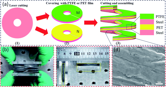
The device structure of a SL-TENG is schematically illustrated in Fig. 1(a), showing the fabricating process of a SL-TENG. The details include: (1) spring steels (Kobetool, Germany, width 50 mm, and thickness 0.1 mm) were cut to be single discs (diameter 4 cm) with a circular hole (diameter 1 cm). (2) The steel discs were first physically sanded, then ultrasonically washed in an ethanol bath for 30 min, and finally dried at 40 °C for 2 h in a vacuum. Thereafter, the disc surfaces were covered with commercial polytetrafluoroethylene (PTFE) (thickness 0.1 mm) and polyethylene glycol terephthalate (PET) (thickness 0.2 mm) films, forming the electrode M and electrode N respectively. Copper wires were adhered to the disc surfaces for the subsequent tests. (3) Spring steel discs of electrodes M and N were cut from the circle centre to the edge directly; each pair of steel discs of electrode M and electrode N were nested together along the incision direction, then stuck tightly with 3M double-side adhesive tape (thickness 0.15 mm) according to the material ranking order of SL-TENG, as shown in Fig. 1(a). Later, by adding spring steel discs of electrode M and electrode N one by one, and repeating the above steps, a retractable SL-TENG was achieved.2.2 Characterization of SL-TENGs
The microscopic surface structure of the spring steel was observed by field emission scanning electron microscopy (FE-SEM JSM-6510). The output voltage of SL-TENGs was measured using an oscilloscope (Agilent DSO-X 3102A). The output current of SL-TENGs was calculated from the voltage of a resistor when connected in the external circuit. In this measurement, acrylic boards at the top and bottom of SL-TENGs were respectively fixed onto the motion module and stator of the linear motor (WMUA512075-06-D). The devices were tested by changing the position of the motion module, vibration frequency, and amplitude.3. Results and discussion
3.1 Working mechanism of a SL-TENG
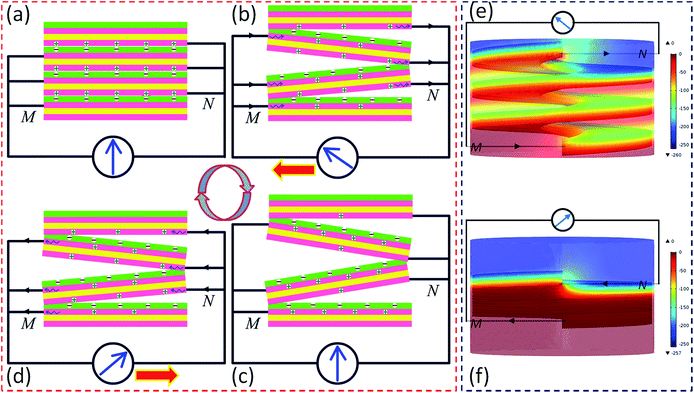
Fig. 1(b and c) are photographs of the as-prepared SL-TENG, showing the appearances of stretched and released devices, respectively. The thickness of the three-layer SL-TENG is merely 4 mm, except for the acrylic boards, which saves a lot of space and materials so as to achieve effective utilization of space for harvesting vibration energy. Under the same conditions, the open-circuit voltage of a single-layer TENG made via sanding surface treatment is about 1.6 times of that without any surface processing (see in ESI Fig. S1†), which demonstrates that due to the sanding treatment, the roughness of the steel surface is improved (see in Fig. 1(d)), leading to the enhancement of the surface charge density of the triboelectric materials of the device.As a SL-TENG has similar construction to a spring, it exhibits good elastic properties. When a SL-TENG converts vibratory mechanical energy into electrical energy in contact/separation mode, the spring steel acts not only as skeleton, but also as triboelectric material and electrode. In view of the absolute synchronicity of an ideal spring structure, Fig. 2 theoretically depicts the working principle of a SL-TENG in detail. At the initial position in Fig. 2(a), each pair of the PTFE film on electrode M and the steel of electrode N of the SL-TENG are well contacted, causing negative charges on the surface of the PTFE film and equal positive charges on the surface of steel, due to the triboelectricity and the large difference of electron affinity between two triboelectric materials. Since PTFE material is an insulator, the charges on the surface of PTFE film can be maintained for a long time so that electricity is generated continuously. When an external force is applied, the SL-TENG begins to stretch, the two friction layers separate synchronously from the contact surfaces, and subsequently an electric field is produced in space; at the same time the induced charges, which are caused by the electrostatic induction effect, transfer across the two electrodes due to the potential difference. This forms a current flow from electrode N to M through the external circuit, as is shown in Fig. 2(b). The charge flowing continues until the SL-TENG reaches the largest displacement position, shown in Fig. 2(c). Thereafter, the electric field is offset and the device is in a static equilibrium. Similarly, once the external force is released, the SL-TENG begins to shrink and the separated surfaces begin to contact synchronously from the largest displacement position, as shown in Fig. 2(d), which results in an inverse output current from electrode M to N until they fully contact (Fig. 2(a)). Thus, a full cycle of electricity generation has been accomplished and thereby a signal of periodic output alternating current is generated. Additionally, COMSOL multi-physics software based on finite-element simulation was employed to demonstrate the potential distribution of the SL-TENG (ESI†) under the open-circuit conditions in the separation state (Fig. 2(e)) and contact state (Fig. 2(f)). Simulation results indicate that when the friction layers begin to separate from the contact state under an applied force, electric current would flow from electrode N to electrode M in order to screen the produced electrostatic field until the device returned back to its static equilibrium, and vice versa. This is consistent with the working mechanism illustrated in Fig. 2(a–d) and further elucidates the working process of the device.
Previous studies have shown that there is a strong correlation between output performance and the contact/separation synchronism for a multi-layer TENG.36,43,44 Due to the complete synchronization of an ideal spring, the current–time waveform of a TENG with a spring structure should be in accord with the normal waveform from a single-layer TENG. To verify the contact/separation synchronization of the SL-TENG devices, a comparison study between a SL-TENG and a typical single-layer TENG was performed, as shown in Fig. 3. Fig. 3(a1–a4) display the output current–time waveform of a SL-TENG with three-layers. It can be intuitively seen that the curve form of SL-TENG is pretty close to that of a single-layer TENG (vs. Fig. 3(b)) except for two or three weak partial peaks. Compared with the result from ref. 43 as shown in Fig. 3(c), only fewer and smaller partial peaks can be observed far from the maximum peak. Undoubtedly, the unique spring structure effectively enhances the contact/separation synchronism of SL-TENGs. More importantly, as vibration frequency increases, the partial peaks gradually begin to disappear. The better contact/separation synchronism of SL-TENGs is also believed to be the reason for the rapid increase of the output current, especially the negative current when increasing the vibration frequency. At an amplitude of 5 mm, it was observed that the maximum negative and positive current, respectively, reach 9.4 μA and 8 μA at a frequency of 7 Hz, which is respectively 4.09 and 2.29 times the maximum current value at a frequency of 2 Hz. These results show that the synchronism is further strengthened as vibration frequency increases, indicating the efficient energy collection and conversion of SL-TENGs. However, a certain number of current partial peaks originating from the asynchronism still exist compared to that of a single-layer TENG. This non-ideality can be attributed to the hand-fabrication of the spring structure. In order to achieve ideal synchronism, it is suggested that both preparation methods and techniques should be improved.
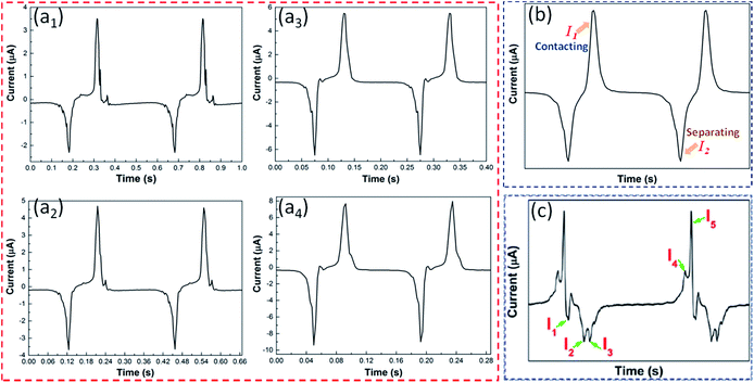 | ||
| Fig. 3 Output current peaks of different TENGs in the two working cycles. (a1–a4) The three-layer SL-TENG at the frequency of 2 Hz, 3 Hz, 5 Hz, and 7 Hz respectively (amplitude of 5 mm). (b) A normal single-layer TENG. (c) The multi-layer TENG from ref. 43. | ||
3.2 Output performances of SL-TENGs
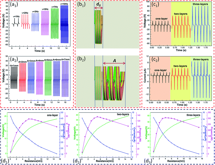
Both frequency and amplitude are key factors that influence the output performance of SL-TENGs. The output voltage with varied frequencies and amplitudes A (Fig. 4(b2)) are respectively shown in Fig. 4(a1 and a2). From Fig. 4(a1), the open-circuit voltage increases continually when increasing the frequency from 1 Hz to 10 Hz at an amplitude of 4 mm, which is likely caused by several factors, as follows: (1) as the frequency increases, the vibration acceleration becomes greater. The more efficient contact of the SL-TENG thus helps the friction layer to accumulate more charges,48 which causes the higher open-circuit voltage values. (2) The output performance for a TENG has its own frequency selectivity which only responds to the trigger signal with a frequency inside its working band.49 Based on frequency selectivity, the open-circuit voltage increases with increasing frequency when it is less than the resonant frequency of the device. In contrast, it decreases with an increase of frequency when it is higher than the resonant frequency. So, the frequency values from our study maybe just distribute within the working frequency range and are less than the resonance frequency of the SL-TENG. (3) The impedance value ∼10 MΩ of our oscilloscope has the same order of magnitude as the internal resistance of SL-TENG from experimental measurements, thus leading to the effect of current shunt in the circuit. Therefore, the observed value from the oscilloscope is the terminal voltage but not the open-circuit voltage. Thus, the voltage increases with frequency, similarly to the output current.Similarly, at a frequency of 5 Hz, the output voltage increases as amplitude increases from 1 mm to 7 mm (Fig. 4(a2)); especially, the open-circuit voltage swiftly increases from 27 V to 36 V when the amplitude raises from 1 mm to 2 mm. This variation can be explained as below: the open-circuit voltage VOC is given by26
Based on the excellent synchronism of the spring structure, a comparison of SL-TENGs with one layer, two layers, and three layers was made. Fig. 4(c1 and c2) show that the open-circuit voltage and short-circuit current of SL-TENGs both increase as the number of layers increases under the same conditions. The peak voltage and current of a three-layer SL-TENG could reach 80 V and 14 μA, respectively, about 267% and 280% of that from a one-layer SL-TENG, and about 145% and 156% of that from a two-layer SL-TENG. In addition, the electricity output capability of SL-TENGs under varied external resistances was studied at a frequency of 10 Hz and amplitude of 5 mm, as depicted in Fig. 4(d1–d3). The output current gradually decreases with increasing resistance. On the contrary, the output voltage shows an opposite trend: the voltage increases with increased resistance. The output powers of the SL-TENGs with one layer, two layers, and three layers reached a maximum of 46 μW, 135 μW, and 306 μW at external load resistances of 6 MΩ, 5 MΩ, and 4 MΩ, respectively. As the number of layers increases, on the one hand, the friction area is enlarged and more charges are produced on the contact surfaces;43 on the other hand, experimental results show that the SL-TENG's internal resistance gradually decreases. For these two reasons, the output performance of a SL-TENG is greatly promoted, far more than double or triple the output of a single-layer device. However, maybe there are other factors determining the open-circuit voltage, which need more investigation in future studies.
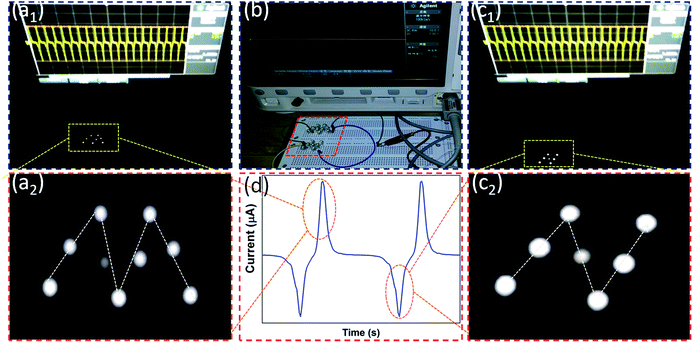
To demonstrate the output capability of a SL-TENG, the three-layer SL-TENG was applied to illuminate tens of LEDs at a frequency of 4 Hz and an amplitude of 5 mm, as shown in Fig. 5. In the test, the ‘M’ and ‘N’ shape LEDs are connected in antiparallel on a breadboard. Fig. 5(b) displays the image when the device is at rest; no LEDs are lit and no electric signal can be detected by an oscilloscope. When the SL-TENG is driven by a liner motor, the ‘M’ and ‘N’ shaped LEDs alternately light up. A signal of alternating current (Fig. 5(d)) is simultaneously generated, as could be seen from the oscilloscope. It was observed that the ‘M’ shape LEDs were lit (Fig. 5(a1)) when a positive current was generated, while the ‘N’ shape LEDs glowed (Fig. 5(c1)) when a negative current flowed. Fig. 5(a2 and c2) are corresponding magnified pictures. It is proved that a SL-TENG can convert vibration energy into alternating electricity and could be applied in self-powered systems of micro-electronic devices. Furthermore, under the frequency of 10 Hz and amplitude of 5 mm, a stability and durability test was carried out for about 10![[thin space (1/6-em)]](https://www.rsc.org/images/entities/char_2009.gif) 000 cycles (testing time was about 18 minutes). The results show almost no change of output performance, as shown in Fig. S2 (ESI†).
000 cycles (testing time was about 18 minutes). The results show almost no change of output performance, as shown in Fig. S2 (ESI†).
3.3 Potential application as a self-powered road condition sensor
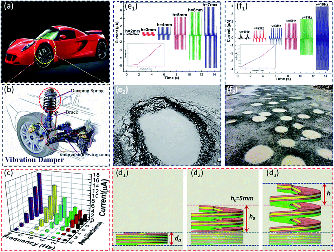
Road condition sensing is a new intelligent technique to monitor road potholes, and a sensor would potentially be used for safer driving (e.g., for a car, Fig. 6(a)). However, to the best of our knowledge, there is no such a sensor with an electric signal generated by the vibration of a damping spring (Fig. 6(b)). Here, we propose a road condition sensor based on the SL-TENG studied in this paper. By taking the brace as the central axis, the SL-TENG with a circular hole can be installed on the outside of the brace and vibrates with the vibration spring. When a car was driven on different roads, the higher frequency and amplitude of the vibration spring could respectively correspond to a greater depth (Fig. 6(e2)) and to more (Fig. 6(f2)) road potholes. In other words, the various depths and numbers of road potholes could also be transformed into the vibration amplitude (Fig. 6(e1)) and frequency (Fig. 6(f1)), respectively.To testify to the feasibility, the experimental measurements were designed and implemented by adjusting both the position of the mobile module on a motor and the vibration settings. First, the SL-TENG was pulled from the original state (Fig. 6(d1)) to the fixed vibration centre position (Fig. 6(d2)) where h0 = 5 mm. The 3D graph of output current on changing frequencies ν and amplitudes h (Fig. 6(d3)) is shown in Fig. 6(c), and it can be intuitively seen that at the same frequency (amplitude), the output current increases as amplitude (frequency) increases. Derived from the corresponding 3D graph, Fig. 6(e1) depicts the varied current with changing amplitudes (ν = 5 Hz), while Fig. 6(f1) displays the varied current as frequency changes (h = 4 mm). From insets in Fig. 6(e1 and f1), it is obvious that the relationship between the output current and frequency (amplitude) is approximately linear at a certain amplitude (frequency). These results attest that the generated electrical signal can be employed for sensing the depth and number of road potholes when a SL-TENG is installed in a car's vibration system.
4. Conclusions
In summary, to improve the synchronism of multi-layer TENGs, we assembled a novel retractable spring-like-electrode TENG for vibratory energy harvesting by employing spring steel as both skeleton and electrode. The SL-TENG works in contact/separation mode, which can convert vibration energy into electricity for a self-powered system. Benefiting from the outstanding elasticity of spring steel, a small volume with a SL-TENG is achieved so that the electricity output can be improved rapidly without a large displacement. More importantly, with the unique retractable spring structure, the contact/separation synchronism of a SL-TENG is integrally enhanced and further strengthened as vibration frequency increases. This can be used to tandem-stack springs to efficiently collect and convert vibration energy in a small volume. At an amplitude of 5 mm, the three-layer SL-TENG can reach a maximum negative current of 9.4 μA and positive current of 8 μA at a frequency of 7 Hz. Meanwhile, the SL-TENG possesses favorable integration ability for power output. The maximum power of a three-layer SL-TENG is 6.7 and 2.3 times of that of one-layer and two-layer SL-TENGs, respectively. The gradual decrease in the internal resistance of the device with an increase in the number of layers is believed to be one of the most important reasons for boosting the output performance of multi-layer SL-TENGs. Additionally, a three-layer SL-TENG was applied to alternately illuminate tens of commercial LEDs, and a SL-TENG is proposed to be used as a self-powered sensor for monitoring road potholes.Conflicts of interest
There are no conflicts to declare.Acknowledgements
We gratefully acknowledge financial support from the National Natural Science Foundation of China (Grant 11274256), the Program for Innovation Team Building at Institutions of Higher Education in Chongqing (CXTDX201601011), the Fundamental Research Funds for the Central Universities (XDJK2017A002), and the Key Laboratory and Scientific Research Foundation of Zunyi City (SSKH[2015]55).References
- F. R. Fan, Z. Q. Tian and Z. L. Wang, Nano Energy, 2012, 1, 328–334 CrossRef CAS.
- H. Y. Guo, J. Chen, L. Tian, Q. Leng, Y. Xi and C. G. Hu, ACS Appl. Mater. Interfaces, 2014, 6, 17184–17189 CAS.
- Y. N. Xie, S. H. Wang, L. Lin, Q. S. Jing, Z. H. Lin, S. M. Niu, Z. Y. Wu and Z. L. Wang, ACS Nano, 2013, 7, 7119–7125 CrossRef CAS PubMed.
- Y. Xi, H. Y. Guo, Y. L. Zi, X. G. Li, J. Wang, J. N. Deng, S. M. Li, C. G. Hu, X. Cao and Z. L. Wang, Adv. Energy Mater., 2017, 1602397 CrossRef.
- Y. F. Hu, J. Yang, Q. S. Jing, S. M. Niu, W. Z. Wu and Z. L. Wang, ACS Nano, 2013, 7, 10424–10432 CrossRef CAS PubMed.
- D. Choi, S. Lee, S. M. Park, H. Cho, W. Hwang and D. S. Kim, Nano Res., 2015, 8, 2481–2491 CrossRef CAS.
- T. Huang, C. Wang, H. Yu, H. Z. Wang, Q. H. Zhang and M. F. Zhu, Nano Energy, 2015, 14, 226–235 CrossRef CAS.
- T. C. Hou, Y. Yang, H. L. Zhang, J. Chen, L. J. Chen and Z. L. Wang, Nano Energy, 2013, 2, 856–862 CrossRef CAS.
- B. Saravanakumar, R. Mohan, K. Thiyagarajan and S. J. Kim, RSC Adv., 2013, 3, 16646–16656 RSC.
- Z. L. Wang, Faraday Discuss., 2014, 176, 447–458 RSC.
- Z. M. Chen, X. Rong and G. Z. Cao, Chin. Micronanoelectron. Technol., 2016, 53, 36–42 Search PubMed.
- A. S. M. I. Uddin and G. S. Chung, RSC Adv., 2016, 6, 63030–63036 RSC.
- Q. Z. Zhong, J. W. Zhong, X. F. Cheng, X. Yao, B. Wang, W. B. Li, N. Wu, K. Liu, B. Hu and J. Zhou, Adv. Mater., 2015, 27, 7130–7136 CrossRef CAS PubMed.
- R. Zhu, J. Jiang, Z. Wang, Z. X. Cheng and H. Kimur, RSC Adv., 2016, 6, 66451–66456 RSC.
- B. Bajaj, S. Hong, S. M. Jo, S. Lee and H. J. Kim, RSC Adv., 2016, 6, 64441–64445 RSC.
- G. Zhu, J. Chen, Y. Liu, P. Bai, Y. S. Zhou, Q. S. Jing, C. F. Pan and Z. L. Wang, Nano Lett., 2013, 13, 2282–2289 CrossRef CAS PubMed.
- S. H. Wang, L. Lin, Y. N. Xie, Q. S. Jing, S. M. Niu and Z. L. Wang, Nano Lett., 2013, 13, 2226–2233 CrossRef CAS PubMed.
- S. M. Niu, Y. Liu, S. H. Wang, L. Lin, Y. S. Zhou, Y. F. Hu and Z. L. Wang, Adv. Funct. Mater., 2014, 24, 3332–3340 CrossRef CAS.
- Y. Yang, H. L. Zhang, J. Chen, Q. S. Jing, Y. S. Zhou, X. N. Wen and Z. L. Wang, ACS Nano, 2013, 7, 7342–7351 CrossRef CAS PubMed.
- S. H. Wang, Y. N. Xie, S. M. Niu, L. Lin and Z. L. Wang, Adv. Mater., 2014, 26, 2818–2824 CrossRef CAS PubMed.
- C. B. Han, C. Zhang, W. Tang, X. H. Li and Z. L. Wang, Nano Res., 2015, 8, 722–730 CrossRef CAS.
- G. D. Zhou, B. Sun, Y. Q. Yao, H. H. Zhang, A. K. Zhou, K. Alameh, B. F. Ding and Q. L. Song, Appl. Phys. Lett., 2016, 109, 143904 CrossRef.
- G. D. Zhou, L. H. Xiao, S. J. Zhang, B. Wu, X. Liu and A. K. Zhou, J. Alloys Compd., 2017, 722, 753–759 CrossRef CAS.
- G. D. Zhou, Y. Q. Yao, Z. S. Lu, X. D. Yang, J. J. Han, G. Wang, X. Rao, P. Li, Q. Liu and Q. L. Song, Nanotechnology, 2017, 28, 425202 CrossRef PubMed.
- X. Z. Wang, B. Yang, J. Q. Liu, Y. B. Zhu, C. S. Yang and Q. He, Sci. Rep., 2016, 6, 36409 CrossRef CAS PubMed.
- J. Chen, H. Y. Guo, X. M. He, G. L. Liu, Y. Xi, H. F. Shi and C. G. Hu, ACS Appl. Mater. Interfaces, 2016, 8, 736–744 CAS.
- X. N. Xia, J. Chen, G. L. Liu, M. S. Javed, X. Wang and C. G. Hu, Carbon, 2017, 111, 569–576 CrossRef CAS.
- M. Wang, W. Li, C. You, Q. Wang, X. S. Zeng and M. F. Chen, RSC Adv., 2017, 7, 6772–6779 RSC.
- D. Kim, H. M. Lee and Y. K. Choi, RSC Adv., 2017, 7, 137–144 RSC.
- G. G. Cheng, W. Fang, J. Zhang, S. Y. Jiang, J. N. Ding, N. S. Pesika, Z. Q. Zhang, L. Q. Guo and Y. Wang, Acta Phys. Sin., 2016, 65, 060201 Search PubMed.
- S. Lee, W. Ko, Y. Oh, J. Lee, G. Baek, Y. Lee, J. Sohn, S. Cha, J. Kim, J. Park and J. Hong, Nano Energy, 2015, 12, 410–418 CrossRef CAS.
- K. N. Kim, Y. K. Jung, J. Chun, B. U. Ye, M. Gu, E. Seo, S. Kim, S. W. Kim, B. S. Kim and J. M. Baik, Nano Energy, 2016, 26, 360–370 CrossRef CAS.
- H. Y. Guo, Q. Leng, X. M. He, M. J. Wang, J. Chen, C. G. Hu and Y. Xi, Adv. Energy Mater., 2014, 1400790 Search PubMed.
- X. N. Xia, G. L. Liu, H. Y. Guo, Q. Leng, C. G. Hu and Y. Xi, Nano Energy, 2015, 15, 766–775 CrossRef CAS.
- P. Bai, G. Zhu, Y. Liu, J. Chen, Q. S. Jing, W. Q. Yang, J. S. Ma, G. Zhang and Z. L. Wang, ACS Nano, 2013, 7, 6361–6366 CrossRef CAS PubMed.
- G. L. Liu, W. N. Xu, X. N. Xia, H. F. Shi and C. G. Hu, J. Mater. Chem. A, 2015, 3, 21133–21139 CAS.
- J. H. Kim, J. Chun, J. W. Kim, W. J. Choi and J. M. Baik, Adv. Funct. Mater., 2015, 25, 7049–7055 CrossRef CAS.
- H. Y. Guo, J. Chen, Q. Leng, Y. Xi, M. J. Wang, X. M. He and C. G. Hu, Nano Energy, 2015, 12, 626–635 CrossRef CAS.
- J. L. Chang, A. Y. Choi, C. Choi, H. J. Sim, S. J. Kim and T. K. Youn, RSC Adv., 2016, 6, 10094–10098 RSC.
- B. Meng, W. Tang, X. S. Zhang, M. D. Han, W. Liu and H. X. Zhang, Nano Energy, 2013, 2, 1101–1106 CrossRef CAS.
- P. Bai, G. Zhu, Z. H. Lin, Q. S. Jing, J. Chen, G. Zhang, J. S. Ma and Z. L. Wang, ACS Nano, 2013, 7, 3713–3719 CrossRef CAS PubMed.
- W. Q. Yang, J. Chen, Q. S. Jing, J. Yang, X. N. Wen, Y. J. Su, G. Zhu, P. Bai and Z. L. Wang, Adv. Funct. Mater., 2014, 24, 4090–4096 CrossRef CAS.
- Y. Kang, B. Wang, S. G. Dai, G. L. Liu, Y. P. Pu and C. G. Hu, ACS Appl. Mater. Interfaces, 2015, 7, 20469–20476 CAS.
- G. L. Liu, H. Y. Guo, L. Chen, X. Wang, D. P. Wei and C. G. Hu, Nano Res., 2016, 9, 3355–3363 CrossRef.
- K. N. Kim, J. P. Lee, S. H. Lee, S. C. Lee and J. M. Baik, RSC Adv., 2016, 6, 88526–88530 RSC.
- T. Jiang, Y. Y. Yao, L. Xu, L. M. Zhang, T. X. Xiao and Z. L. Wang, Nano Energy, 2017, 31, 560–567 CrossRef CAS.
- C. S. Wu, R. Y. Liu, J. Wang, Y. L. Zi, L. Lin and Z. L. Wang, Nano Energy, 2017, 32, 287–293 CrossRef CAS.
- S. L. Zhang, Y. C. Lai, X. He, R. Y. Liu, Y. L. Zi and Z. L. Wang, Adv. Funct. Mater., 2017, 27, 1606695 CrossRef.
- A. F. Yu, X. Y. Chen, R. Wang, J. Y. Liu, J. J. Luo, L. B. Chen, Y. Zhang, W. Wu, C. H. Liu, H. T. Yuan, M. Z. Peng, W. G. Hu, J. Y. Zhai and Z. L. Wang, ACS Nano, 2016, 10, 3944–3950 CrossRef CAS PubMed.
Footnote |
| † Electronic supplementary information (ESI) available. See DOI: 10.1039/c7ra09911h |
| This journal is © The Royal Society of Chemistry 2017 |

