 Open Access Article
Chemical vapor deposition-assisted fabrication of a graphene-wrapped MnO/carbon nanofibers membrane as a high-rate and long-life anode for lithium ion batteries†
Juan Wangab,
Chao Lib,
Zhenyu Yang *ab and
Deliang Chen*b
aSchool of Chemical Engineering and Energy Technology, Dongguan University of Technology, Dongguan, Guangdong 523808, P. R. China
bSchool of Chemistry, Nanchang University, No. 999, Xuefu Road, Nanchang, Jiangxi, China. E-mail: zyyang@ncu.edu.cn; dlchen@zzu.edu.cn; Tel: +86-131-77812780
First published on 1st November 2017
Abstract
In this work, we have fabricated a graphene-wrapped MnO/carbon nanofibers (MnO/CNFs@G) membrane by a facile electrospinning technique followed by an ambient pressure chemical vapor deposition (APCVD) process. The resultant MnO/CNFs@G membrane with uniform MnO particle distribution in porous carbon nanofibers and with a graphene layer covering not only facilitates the transport of both electrolyte ions and electrons to the MnO surface, but also relieves the pulverization that originated from the large volume change of MnO during the charge/discharge cycles. Interestingly, the free-standing and binder-free MnO/CNFs@G membranes can deliver a high reversible capacity of 946.5 mA h g−1 when the current density is switched back to 0.1 A g−1 after 110 cycles. Even at a high rate (10 A g−1), the electrode can still keep 426.7 mA h g−1 after 5000 cycles with coulombic efficiency of above 99%. This is the best specific capacity and longest cycling life reported for the MnO composite film anodes. We believe that the approach based on CNFs and CVD graphene as a structural support for the transition metal oxide can be potentially extended to improve the electrochemical performance of other electrode materials in lithium ion batteries.
1. Introduction
Over the past years, the development of flexible Li-ion batteries (LIBs) has been more and more important for portable electronic devices. For example, smart communication, wearable devices, etc. However, the fabrication of flexible electrodes with long cycle life and high specific capacity in commercial applications is still a great challenge.1–4 Conventionally, graphite is used as an anode material for commercial lithium ion batteries. However, graphite suffers from an inherently low theoretical charge storage capacity (372 mA h g−1) and often operates at significantly lower rates (typically, <1C) that in turn limits the achievable power densities.5–7 For the purpose of improving the energy density and power density of batteries, scientists have made great efforts to explore alternative anode materials with higher capacity, such as Si,8 SnO2,9 Co3O4,10 FeOx,11,12 and MnOx.13–15Among these anode materials investigated for LIBs, MnO is an attractive anode material because of its low conversion potential (average discharge and charge voltages of 0.5 V and 1.2 V vs. Li/Li+, respectively), low voltage hysteresis (<0.8 V), high density (5.43 g cm−3), low cost, non-toxicity, and the high abundance of Mn on earth.16–18 However, it still remains great challenges for the application of MnO in commercial LIBs. Its biggest obstacles toward LIBs is that the large volume expansion and severe collapse occurs in the host matrix of MnO during the cycling processes give rise to pulverization, which results in poor cycling stability and inferior rate capability.19,20 Meanwhile MnO-based electrodes have poor rate capability as a result of poor electronic conductivity.21,22
Recently, some efforts have been performed to deal with these issues. An effective strategy is to fabricate nano-scale composites with a carbonaceous matrix.13–17 Based on it, some MnO/C hybrids have been developed, such as MnO/mesoporous carbon,16 MnO/graphene,17 MnO/carbon nanowires,23 and MnO/carbon nanotube,24 etc. Although the incorporation of carbonaceous matrix has significantly enhanced electrochemical performances, these MnO composites are still confronted with limited reversible cycling life and capacities. The fracture of anode materials was found to occur during a certain number of cycles because of the limited elasticity of the shell material and the shortcomings of integrity and regularity in the structure, which meant that the electrochemical performance could not be effectively maintained. Moreover, in most cases the aforementioned products were in powder. The electrode fabrication required to add extra conductive additives and binders, and then includes complex slurry casting procedures.
In comparison, an electrode with freestanding and binder free film avoids the use of electrochemical inactive components, e.g. binders, conductive additives, and/or current collectors, which account for about 50 wt% of the electrode. When considering these components, the freestanding, binder-free and flexible membrane electrodes would be much more appealing. It is known that electrospinning is a versatile method for fabrication of composite film by ejecting a polymer composite solution from a syringe needle under an electric field gradient. In recent years, the composite thin film has been produced with electrospinning as free standing and binder-free film anode materials with high theoretical capacity for lithium ion batteries. For example, Huang's group fabricated the composite film electrode of MnO/carbon nanofibers by an electrospinning technique, but a polymeric binder was still used for the fabrication of the electrodes.25 Zhao's group designed a flexible membrane through incorporating MnO2 nanowires into polymer solution, which exhibits a high reversible capacity of 987.3 mA h g−1 after 150 discharge/charge cycles at 0.1 A g−1, a good rate capability (406.1 mA h g−1 at 3 A g−1) and an excellent cycling performance (655 mA h g−1 over 280 cycles at 0.5 A g−1).26–28
However, to the best of our knowledge, MnO-based flexible membranes anode materials with long cycle life (e.g., >1000 cycles), and excellent rate capability (e.g., >300 mA h g−1 at 10![[thin space (1/6-em)]](https://www.rsc.org/images/entities/char_2009.gif) 000 mA h g−1) have never been reported for lithium storage to date. Also, there has been no report on fabricating CVD graphene-wrapped MnO/C nanofiber membranes and using it as flexible anodes for Li-ion batteries, although CVD is potentially the most attractive technique for direct synthesis of high quality graphene on various flexible substrates among the many graphene synthesis methods available.
000 mA h g−1) have never been reported for lithium storage to date. Also, there has been no report on fabricating CVD graphene-wrapped MnO/C nanofiber membranes and using it as flexible anodes for Li-ion batteries, although CVD is potentially the most attractive technique for direct synthesis of high quality graphene on various flexible substrates among the many graphene synthesis methods available.
Herein, we construct a graphene-wrapped structure of MnO/C nanofibers membrane through electrospinning followed by an ambient pressure chemical vapor deposition (APCVD) reaction process, since that APCVD is an inexpensive and simplified method for high-throughput growth of graphene. In such membrane structure, the MnO surface will be covered by graphene; the flexible network of graphene will prevent the electrolyte from reaching the MnO surface directly; the lithiation of the MnO will be occurred by Li diffusion through graphene to the surface of MnO, which allows for anti-pulverization ability of MnO and good kinetics upon lithiation. As expected, the freestanding and binder-free graphene-wrapped membranes electrode exhibits high lithium-storage capacity, impressive rate capability, and superior cyclability, due to the synergetic effects of APCVD graphene and MnO/CNFs. Interestingly, it delivers a high reversible capacity of 946.5 mA h g−1 when the current density is switched back to 0.1 A g−1 after 110 cycles. Even at high rate (10 A g−1), the electrode can still keep 426.7 mA h g−1 after 5000 cycles with coulombic efficiency of above 99%. This is the best specific capacity and longest cycling life reported for the flexible MnO composite membrane anodes.
2. Experimental
2.1 Materials
Polyacrylonitrile (PAN, Mw = 150![[thin space (1/6-em)]](https://www.rsc.org/images/entities/char_2009.gif) 000) and manganese(II) acetate tetra hydrate (Mn(Ac)2·4H2O, 99.9%) were purchased from J&K Chemical. N,N-Dimethyl-formamide (DMF, AR) was purchased from Sinopharm Chemical Reagent Co., Ltd. All these reagents were used without further purification.
000) and manganese(II) acetate tetra hydrate (Mn(Ac)2·4H2O, 99.9%) were purchased from J&K Chemical. N,N-Dimethyl-formamide (DMF, AR) was purchased from Sinopharm Chemical Reagent Co., Ltd. All these reagents were used without further purification.
2.2 Fabrication of Mn(Ac)2/PAN nanofiber membranes
A PAN solution was prepared by dissolving 0.8 g of PAN in 10 mL of DMF at 50 °C with vigorous stirring for 6 h. Amounts of 1.0 g of Mn(Ac)2·4H2O in stoichiometric ratios were dissolved in the solution of PAN/DMF and stirred at 50 °C for 12 h in order to obtain homogeneous viscous mixtures. Then, the as-prepared precursor solution was loaded into a plastic syringe with a stainless steel nozzle. With a syringe pump (0.8 mL h−1) and an applied voltage of 17 kV between the electrospinning jet and the collector (15 cm), the Mn(Ac)2/PAN nanofiber membranes was obtained. Then the nanofiber membranes were firstly heated at 280 °C in air for 2 h to promote stabilization.2.3 Fabrication of MnO/CNFs@G membranes
Graphene was directly grown on MnO/PAN nanofiber membranes using ambient pressure chemical vapor deposition (APCVD) method. The growth protocol consisted of three steps: (1) the nanofiber membranes was heated to 1020 °C in 110 min under the atmosphere of Ar (500 sccm) and H2 (30 sccm), then staying at this temperature for 30 min; (2) a nominal amount of CH4 (30 sccm) was brought into the reaction tube for 15 min; (3) the samples were cooled to room temperature with Ar (500 sccm) and H2 (30 sccm). Then the MnO/CNFs@G membranes were obtained. For the controlled experiment, the MnO/CNFs were conducted at the same condition except for the addition of CH4 in the growth procedure.2.4 Characterization
The crystal structures of the obtained samples were determined by X-ray diffraction (XRD, Bruker XD-3 Focus X-ray diffractometer) using Cu Kα radiation over the range of 2θ = 5–80°, the morphology and structure of products were examined using a scanning electron microscopy (SEM, Hitachi-S4800) and transmission electron microscopy (TEM, TEKNAI F20; 200 kV acceleration voltage) and high-resolution TEM. X-ray photoelectron spectra (XPS) were recorded using a Kratos Analytical Axis-Ultra spectrometer with a monochromatic Al Kα X-ray source. Raman spectroscopy was performed with a microscopic confocal Raman spectrometer (Jobin Yvon LabRAM HR 800UV; 514.5 nm, 25 mW).2.5 Cell fabrication and electrochemical measurements
Electrochemical experiments of the half cell were carried out on CR 2025 coin cells, which were assembled in an Ar-filled MBraun glove box. Li metal was used as counter electrode and Celgard 2400 as the separator. The as-obtained fabrics were tailored into freestanding discs with 10 mm in diameter, which were directly used as the working electrode without any binders, conductive additives. The electrolyte was 1 M LiPF6 dissolved in a mixture of ethylene carbonate/dimethyl carbonate/diethyl carbonate (EC/DMC/DEC = 1![[thin space (1/6-em)]](https://www.rsc.org/images/entities/char_2009.gif) :
:![[thin space (1/6-em)]](https://www.rsc.org/images/entities/char_2009.gif) 1
1![[thin space (1/6-em)]](https://www.rsc.org/images/entities/char_2009.gif) :
:![[thin space (1/6-em)]](https://www.rsc.org/images/entities/char_2009.gif) 1, v/v). The coin cells were galvanostatically cycled between 2.5 and 0.01 V (vs. Li/Li+) using a LAND (CT2001A) battery measurement system at room temperature. Cyclic voltammogram (CV) experiment was performed in the potential window of 0.01–3.0 V at a scanning rate of 0.5 mV s−1. Electrochemical impedance spectroscopy (EIS) tests were measured in the frequency range from 100 kHz to 0.1 Hz on an electrochemical workstation (Im6e, Zahner).
1, v/v). The coin cells were galvanostatically cycled between 2.5 and 0.01 V (vs. Li/Li+) using a LAND (CT2001A) battery measurement system at room temperature. Cyclic voltammogram (CV) experiment was performed in the potential window of 0.01–3.0 V at a scanning rate of 0.5 mV s−1. Electrochemical impedance spectroscopy (EIS) tests were measured in the frequency range from 100 kHz to 0.1 Hz on an electrochemical workstation (Im6e, Zahner).
3. Results and discussion
The fabrication process of the flexible MnO/CNFs@G composite membranes is illustrated in Fig. 1. Typically, a homogeneous viscous solutions with Mn(Ac)2·4H2O dissolved in PAN/dimethylformamide (DMF) was electrospun into the film of nanofibers, following with stabilization process in air. Then, graphene has been grown on the film by APCVD process in a horizontal quartz tube at 1020 °C. The fabricated films have a pale yellow color due to the existence of Mn2+, and then the color is changed to black after APCVD process.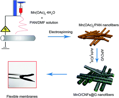 | ||
| Fig. 1 Schematic illustration of the fabrication process of the flexible MnO/CNFs@G nanofiber membranes. | ||
The structural changes of MnO/CNFs@G composite membranes have been conducted by XRD experiments as shown in Fig. 2a. It shows that all the fundamental peaks can be easily indexed to the typical cubic phase of MnO (PDF no. 07-0230). The films of MnO/CNFs@G and MnO/CNFs appear to have a similar profile compared with the results of pure MnO. The main peaks at 2θ ≈ 34.9, 40.5, 58.7, 70.2, and 73.8° can be indexed as (111), (200), (220), (311) and (222) reflections of cubic MnO.21,29,30 A broad peak has been observed at 2θ ≈ 26°, which can be ascribed to carbon. This is probably the presence of low crystalline carbon.
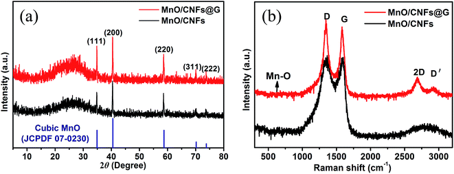 | ||
| Fig. 2 (a) XRD patterns of the nanofiber membranes of MnO/CNFs and MnO/CNFs@G; (b) Raman spectrum of the nanofiber membranes of MnO/CNFs and MnO/CNFs@G. | ||
The structural change of MnO/CNFs@G composites can be also reflected by the Raman spectra as shown in Fig. 2b. The peaks centered at 1350 cm−1 and 1587 cm−1 can be indexed to the D (disordered carbon) and G (graphite) bands of carbon in MnO/CNFs@G and MnO/CNFs composites,31,32 respectively, and the Raman band at 643 cm−1 can be ascribed to the stretching vibration of Mn–O bond in MnO.20 Compared to the MnO/CNFs, the Raman spectra for the film of MnO/CNFs@G have been found the peaks at about 2685 cm−1 and 2922 cm−1, which are assigned to the 2D and D′ band of graphene, respectively. The shape of 2D band is typical sign of multilayer graphene.33,34 Therefore, the sample of MnO/CNFs@G composite appears to be wrapped by graphene network structure with a relatively high degree of graphitization and thus is expected to improve the electronic conductivity of the composite membranes.
To further analyze the elemental composition and chemical states of MnO/CNFs@G membranes, X-ray photoelectron spectra (XPS) analyses were carried out. As shown in Fig. 3a, the survey scan spectrum only reveals the peaks of manganese, carbon, oxygen, and nitrogen, indicating a high purity of as-prepared MnO/CNFs@G composite membranes. Fig. 3b displays the high resolution XPS spectra of Mn 2p. The binding energies of Mn 2p1/2 peak at 653.6 eV, Mn 2p3/2 peak at 641.5 eV, and a splitting satellite peak at 644.7 eV are observed between the Mn 2p3/2 and Mn 2p1/2 peaks which was assigned to its purely divalent nature, implying that the oxidation state of Mn element in the composites were of Mn2+ only. It was corresponded to the previous results.25,35 Fig. 3c shows the high-resolution XPS spectrum for C 1s, which can be deconvoluted into four peaks. The strong C 1s peak at 284.5 eV corresponds to graphitic carbon in the MnO/CNFs@G composites, including graphene, while the weaker peak including (N–C, 285.4 eV; C![[double bond, length as m-dash]](https://www.rsc.org/images/entities/char_e001.gif) O, 287.5 eV; O–C
O, 287.5 eV; O–C![[double bond, length as m-dash]](https://www.rsc.org/images/entities/char_e001.gif) O, 289.9 eV).27,36 The peak of C 1s is attributed to the C species that results from the carbonization and dehydration of the manganese alkoxide derivatives or glycolates by APCVD thermal treatment. In Fig. 3d, the characteristic of MnO is shown by the peak of O 1s at 529.8 eV, which displays the Mn–O–Mn state in MnO. Furthermore, the small peak of O 1s at 532.2 eV also indicates the existence of residual O2− bonded with C atoms in the sample,25,37 which shows the interaction between MnO and carbon matrix in the MnO/CNFs@G composites. The existence of MnO interacted or bonded with C atoms in MnO/CNFs@G composites enable the carbon matrix or graphene nanosheets to bind with the MnO particles. This is important because it limits surface diffusion/migration and agglomeration of MnO particles and also enables efficient charge transfer between the MnO particles and carbon matrix.
O, 289.9 eV).27,36 The peak of C 1s is attributed to the C species that results from the carbonization and dehydration of the manganese alkoxide derivatives or glycolates by APCVD thermal treatment. In Fig. 3d, the characteristic of MnO is shown by the peak of O 1s at 529.8 eV, which displays the Mn–O–Mn state in MnO. Furthermore, the small peak of O 1s at 532.2 eV also indicates the existence of residual O2− bonded with C atoms in the sample,25,37 which shows the interaction between MnO and carbon matrix in the MnO/CNFs@G composites. The existence of MnO interacted or bonded with C atoms in MnO/CNFs@G composites enable the carbon matrix or graphene nanosheets to bind with the MnO particles. This is important because it limits surface diffusion/migration and agglomeration of MnO particles and also enables efficient charge transfer between the MnO particles and carbon matrix.
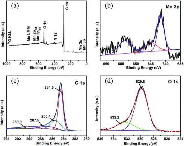 | ||
| Fig. 3 XPS spectra of MnO/CNFs@G nanofiber membranes: (a) full scan XPS spectrum; high-resolution XPS spectra of Mn 2p (b), C 1s (c) and O 1s (d). | ||
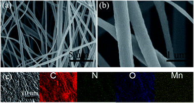
Fig. 4 displays the morphology and size of the electrospun resultant composite membrane by SEM and elemental mapping. From Fig. 4a, we can see that the composite nanofibers are smooth and continuous with diameters of 200–300 nm in obtained MnO/CNFs@G membrane. The fibrous shape and distribution can be maintained well despite passing a APCVD thermal processing in Ar/H2 at 1020 °C for 5 h, and no individual or accumulation of particles was observed. The elemental mapping in Fig. 4c shows the C, N, O and Mn elements are homogeneously distributed throughout the membranes.
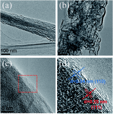
Fig. 5a and b show HRTEM images of the MnO/CNFs@G nanofiber membranes. Large quantities of wormhole-like pores are found in MnO/C nanofibers. The MnO nanoparticles are homogeneously encapsulated in the porous carbon nanofibers, which is in favor of contacting the electrolyte with active materials and the transfer of electron and lithium ions. Fig. 5c and d show the MnO nanocrystals that are surrounded by amorphous carbon or graphene. The lattice fringe with a spacing of 0.25 nm corresponds to the (111) plane of the cubic MnO phase;22 a spacing of 0.34 nm corresponds to the highly organized crystal carbon structure, which is thought as the graphene layer.38,39 These results are consistent with the XRD measurements, showing the typical cubic phase of MnO. Such surface structure with APCVD graphene covered for the MnO/CNFs@G nanocomposite or MnO embedding in the amorphous carbon is expected to provide a flexible buffer to accommodate volume change during lithium insertion/extraction and increase the electronic conductivity simultaneously, which might help to improve their cycle stability and rate performance.
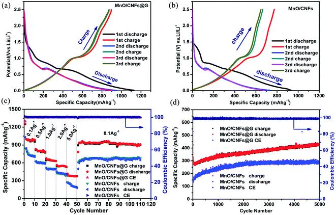
The freestanding MnO/CNFs@G membranes have been directly used as anodes in coin-type Li half-cells and their electrochemical performance were studied. In a control experiment, MnO/CNFs membranes, which were treated under the same condition, were also investigated. Fig. 6a and b show the discharge–charge curves of the MnO/CNFs@G and MnO/CNFs membranes electrodes at 0.1 A g−1 for the first three cycles. As displayed in Fig. 6a and b, a continuous voltage plateau at about 0.5 V appeared, which can be attributed to the reduction from manganese ion with high valence state to Mn during the lithiation process; the subsequent delithiation charge curves show no apparent plateaus but a gentle slope from 1.0 to 1.3 V due to transformation between different oxidation states (Mn2+/Mn). It is found that the initial discharge capacities of the MnO/CNFs@G and MnO/CNFs membrane electrodes are approximately 1127.4 mA h g−1 and 1063.1 mA h g−1 respectively in the first cycle, then the membranes exhibits a similar capacity fading, and the discharge capacity is only 952.7 mA h g−1 and 897.8 mA h g−1 in the second cycle, respectively. As can be seen, the samples exhibit similar profile with a certain irreversible specific capacity in the initial discharge–charge process, presumably due to form a solid electrolyte interface layer and the decomposition of the electrolyte as well as formed Li2O. The discharge–charge curves for the MnO/CNFs@G and MnO/CNFs membranes in the different cycles at 0.1 A g−1 in Fig. 6a and b also demonstrate that the composite gradually reach a stable status in the second and subsequent cycles, and the reversible capacity and first coulombic efficiency are improved by rational design of the CVD graphene-wrapped MnO/CNFs membrane structures.
In order to further identify the superior rate capabilities of the MnO/CNFs@G membranes originated from the synergistic effect of MnO, CNFs and graphene, the rate performances of the MnO/CNFs@G and MnO/CNFs membranes at different current densities from 0.1 A g−1 to 5.0 A g−1 are shown in Fig. 6c. Compared with the MnO/CNFs membrane electrode in control experiment, the MnO/CNFs@G membrane exhibits higher specific capacity of 1011.3, 801.2, 646.1, 545.9 and 382.7 mA h g−1 (the average values) at current densities of 0.1, 0.5, 1.0, 2.0, and 5.0 A g−1. Moreover, a reversible capacity of 946.5 mA h g−1 is recovered after 110 cycles for MnO/CNFs@G when the current density is switched back to 0.1 A g−1, giving high capacity retention of 94.5%. However, the pristine sample of MnO/CNFs shows a significant lower capacity 612.7 mA h g−1 with a capacity retention of 68.9% while the current density is switched back to 0.1 A g−1. In addition, it is interesting to see that the composite electrodes are still able to deliver the capacity of 693.2 mA h g−1 and 548.1 mA h g−1 after 500 cycles, respectively, when the current densities are to 2 A g−1 and 5 A g−1 (Fig. S2†). More interestingly, the MnO/CNFs@G membrane electrodes can still deliver a reversible capacity of 426.7 mA g−1 after 5000 cycles with 99.9% coulombic efficiency (Fig. 6d) at 10 A g−1, which further display its excellent rate performance and cycling stability during the lithiation–delithiation processes. This is the best high-rate specific capacity and longest cycling life reported for the MnO composite membrane anodes, comparing with the previously work (Table S1†). These results can be attributed to its unique CVD graphene wrapped membrane architecture characteristics, including the uniform MnO distribution in porous carbon nanofibers and the exposed surface of MnO covered by graphene, which is in favor of preventing the electrolyte from reaching the MnO surface directly, and relieving the strain induced by the volume change in charge–discharge cycles.
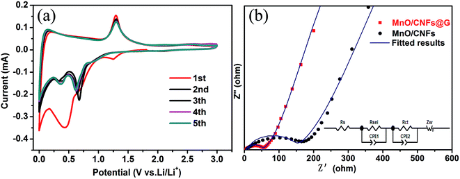
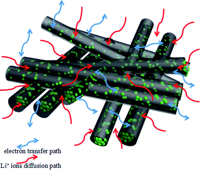
In order to better understand the lithium-storage reaction and kinetics of MnO/CNFs@G composites, the cyclic voltammetry curves and electrochemical impedance spectra have been also investigated. Fig. 7a shows the cyclic voltammetry (CV) curves of the MnO/CNFs@G electrode at a scan rate of 0.5 mV s−1 between 0.01 and 3.0 V in the first five cycles. One small peak appeared at 1.25 V during the process of initial cathodic scan, and disappeared in the subsequent cycles. These reduction peak may correspond to the reduction of manganese ion with high valence state, which could be originated from trace MnO1+x impurity from the sintering process. An irreversible reduction peak at around 0.013 V corresponds to the decomposition of the electrolyte and the formation of the SEI layer.37,40 Furthermore, a strong peak around about 0.45 V corresponds to Mn2+ to Mn0 (MnO + 2Li+ + 2e− → Mn + Li2O), which shifts significantly to 0.30 V and 0.57 V in the subsequent cycles, and this is probably due to the structural change and active materials utilization after the first cycle. In the anodic scan, the strong peak around about 1.3 V could be ascribed to the oxidation of Mn0 to Mn2+ (Mn + Li2O → MnO + 2Li+ + 2e−).41,42 Additionally, after the first cycle, the redox peak intensities become stable, which indicate the highly reversible electrochemical reactions in the MnO/CNFs@G electrode and lead to the enhanced electrochemical processes.43,44 Fig. 7b shows the Nyquist plots of MnO/CNFs@G and MnO/CNFs membranes electrode. The impedance spectrum of each sample is comprised of one semicircle in the high-frequency region and a straight line in the low-frequency region, which are attributed to the charge-transfer process and the diffusion of lithium ions. The experimental results can be well coincide with the equivalent circuit (the inset in Fig. 7b). The diameter of semicircle of MnO/CNFs@G electrode in the Nyquist plots is smaller than the MnO/CNFs electrode, suggesting that the MnO/CNFs@G has a much lower electrolyte resistance and charge transfer resistance than those of MnO/CNFs.45 These results confirm that the introduction of graphene by APCVD is beneficial to further improve the electronic conductivity and lithium ion diffusion of MnO/CNFs. Also, the low impedance can be attributed to higher surface area, uniform MnO particle distribution, and better electrolyte wettability associated with porous structure in the composite membrane material, as illustrated as Fig. 8. These aforementioned factors translate to greater accessibility to active sites for the lithium ions, shorter diffusion distances and quicker lithium ion diffusion, thereby explaining the significantly better rate capability and excellent cycling performance of the MnO/CNFs@G composite membrane electrode.
4. Conclusions
In summary, we have fabricated the MnO/CNFs@G nanofiber membranes by a facile and practical electrospinning technique followed an ambient pressure chemical vapor deposition (APCVD) process. The resultant MnO/CNFs@G membrane structure with uniform MnO particle distribution in porous CNFs and graphene covering layer not only facilitates the transport of both electrolyte ions and electrons to the electrode surface, but also enhances the utilization of the active materials. In addition, such architecture of MnO/CNFs@G is in favor of relieving the pulverization originated from the large volume change of electrode materials during the charge/discharge cycles. The flexible MnO/CNFs@G membranes demonstrates excellent rate performance and cycling stability, which can deliver a reversible capacity of 946.5 mA h g−1 when the current density is switched back to 0.1 A g−1 after 110 cycles at different current densities. More interestingly, the MnO/CNFs@G membrane electrodes can still keep a reversible capacity of 426.7 mA g−1 after 5000 cycles at A g−1 with 99.9% coulombic efficiency. We believe that the approach on the basis of CNFs and APCVD graphene as a structure support for transition metal oxide can be potentially extended to improve the electrochemical performance of other electrode materials in lithium ion batteries.Conflicts of interest
There are no conflicts to declare.Acknowledgements
This work was financially supported by the National Natural Science Foundation of China (No. 21263016, 51432002 and 51502077).References
- J. Deng, L. Chen and Y. Sun, Carbon, 2015, 92, 177–184 CrossRef CAS.
- H. Lin, Y. Zhang, H. Rong and S. Mai, J. Mater. Chem. A, 2014, 2, 11987–11995 CAS.
- N. Loeffler, D. Bresser and S. Passerini, Johnson Matthey Technol. Rev., 2015, 59, 34–44 CrossRef CAS.
- D. Wang, I. Belharouak, G. Zhou and K. Amine, Adv. Funct. Mater., 2013, 23, 1070–1075 CrossRef CAS.
- Z. Li, G. Wu, D. Liu and W. Wu, J. Mater. Chem. A, 2014, 2, 7471–7477 CAS.
- T. Kuilla, S. Bhadra, D. Yao and N. H. Kim, Prog. Polym. Sci., 2010, 35, 1350–1375 CrossRef CAS.
- T. Zhang, J. Liu, C. Wang and X. Leng, Biosens. Bioelectron., 2017, 89, 28–42 CrossRef CAS PubMed.
- H. Wu and Y. Cui, Nano Today, 2012, 7, 414–429 CrossRef CAS.
- Z. Li, G. Wu, S. Deng and S. Wang, Chem. Eng. J., 2016, 283, 1435–1442 CrossRef CAS.
- G. L. Xu, J. Li and L. Huang, Nano Energy, 2013, 2, 394–402 CrossRef CAS.
- L. Liu, H. Zhang, S. Liu and H. Yao, Electrochim. Acta, 2016, 219, 356–362 CrossRef CAS.
- H. Zhou, J. Nanda and S. K. Martha, J. Phys. Chem. Lett., 2013, 4, 3798–3805 CrossRef CAS.
- J. Zhang, W. Zhang, T. He, J. N. Li and S. C. Mu, Carbon, 2017, 115, 95–104 CrossRef CAS.
- Q. Sun and Z. J. Zhang, ACS Appl. Mater. Interfaces, 2016, 8, 6303–6308 CAS.
- W. M. Chen, L. Qie, Y. Shen and Y. M. Sun, Nano Energy, 2013, 2, 412–418 CrossRef CAS.
- X. Zhao, Y. X. Du, L. Jin and Q. H. Zhang, Sci. Rep., 2015, 5, 14146 CrossRef CAS PubMed.
- C. C. Li, H. Yu, Q. Y. Yan and H. H. Hng, Electrochim. Acta, 2016, 187, 406–412 CrossRef CAS.
- S. Z. Huang, Q. Zhang and W. B. Yu, Electrochim. Acta, 2016, 222, 561–569 CrossRef CAS.
- Y. Xia, Z. Xiao, X. Dou, H. Huang and X. H. Lu, ACS Nano, 2013, 7, 7083–7092 CrossRef CAS PubMed.
- X. Fang, X. Lu, X. Guo and Y. Mao, Electrochem. Commun., 2010, 12, 1520–1523 CrossRef CAS.
- N. A. Barakat, S. J. Park and M. S. Khil, Mater. Sci. Eng., B, 2009, 162, 205–208 CrossRef CAS.
- W. Zhu, H. Huang, W. Zhang, X. Tao and Y. Gan, Electrochim. Acta, 2014, 152, 286–293 CrossRef.
- W. Luo, X. Hu and Y. Sun, ACS Appl. Mater. Interfaces, 2013, 5, 1997–2003 CAS.
- Y. Sun, X. Hu and W. Luo, Adv. Funct. Mater., 2013, 23, 2436–2444 CrossRef CAS.
- C. Zhang, J. G. Wang and D. Jin, Electrochim. Acta, 2015, 180, 990–997 CrossRef CAS.
- X. Cui, Y. Wang, Z. Chen, H. Zhou and Q. Xu, Electrochim. Acta, 2015, 180, 858–865 CrossRef CAS.
- B. Liu, X. Hu, H. Xu and W. Luo, Sci. Rep., 2014, 4, 4229 CrossRef PubMed.
- Y. Mai, D. Zhang, Y. Qiao and C. Gu, J. Power Sources, 2012, 216, 201–207 CrossRef CAS.
- J. G. Wang, Y. Yang, Z. H. Huang and F. Kang, Electrochim. Acta, 2015, 170, 164–170 CrossRef CAS.
- Y. Sun, X. Hu, W. Luo and Y. Huang, J. Mater. Chem., 2012, 22, 19190–19195 RSC.
- A. C. Ferrari, Solid State Commun., 2007, 143, 47–57 CrossRef CAS.
- A. C. Ferrari, J. Meyer, V. Scardaci and C. Casiraghi, Phys. Rev. Lett., 2006, 97, 187401 CrossRef CAS PubMed.
- R. Yang, S. Wu, D. Wang and G. Xie, Nano Res., 2014, 7, 1449–1456 CrossRef CAS.
- X. Chen, L. Zhang and S. Chen, Synth. Met., 2015, 210, 95–108 CrossRef CAS.
- F. Gao, J. Y. Qu and Z. B. Zhao, New Carbon Materials, 2014, 29, 316–321 CrossRef.
- X. Gu, J. Yue and L. Chen, J. Mater. Chem. A, 2015, 3, 1037–1041 CAS.
- H. Liu, Z. Li and Y. Liang, Carbon, 2015, 84, 419–425 CrossRef CAS.
- K. K. Bai, Y. Zhou and H. Zheng, Phys. Rev. Lett., 2014, 113, 086102 CrossRef PubMed.
- Y. Liu, Y. Hu and J. Zhang, J. Phys. Chem. C, 2014, 118, 8993–8998 CAS.
- G. L. Xu, Y. F. Xu, H. Sun and F. Fu, Chem. Commun., 2012, 48, 8502–8504 RSC.
- H. Hu, H. Cheng, Z. Liu and Y. Yu, Electrochim. Acta, 2015, 152, 44–52 CrossRef CAS.
- A. Zheng, X. Yang, X. Wu and L. Zhang, J. Electrochem. Soc., 2016, 163, A722–A726 CrossRef CAS.
- F. An, A. Balantekin and H. Band, Phys. Rev. Lett., 2014, 112, 061801 CrossRef CAS PubMed.
- M. Liu, W. Xie and L. Gu, Beilstein J. Nanotechnol., 2016, 7, 1289–1295 CrossRef CAS PubMed.
- Y. F. Xu, G. L. Xu, H. Su and Y. Chen, J. Alloys Compd., 2016, 676, 156–163 CrossRef CAS.
Footnote |
| † Electronic supplementary information (ESI) available. See DOI: 10.1039/c7ra09942h |
| This journal is © The Royal Society of Chemistry 2017 |

