 Open Access Article
The recycle of red mud as excellent SCR catalyst for removal of NOx†
Changming Lia,
Hong Zengab,
Pingle Liub,
Jian Yu *a,
Feng Guoa,
Guangwen Xu
 ac and
Zhan-guo Zhangd
aState Key Laboratory of Multi-phase Complex Systems, Institute of Process Engineering, Chinese Academy of Sciences, Beijing 100190, China. E-mail: yujian@ipe.ac.cn
bSchool of Chemical Engineering, Xiangtan University, Xiangtan, Hunan 411105, PR China
cInstitute of Industrial Chemistry and Energy Technology, Shenyang University of Chemical Technology, Shenyang 110142, China
dNational Institute of Advanced Industrial Science and Technology (AIST), 16-1 Onogawa, Tsukuba, 305-8569 Ibaraki, Japan
First published on 22nd November 2017
Abstract
The development of new routes for the utilization of red mud (RM) waste is very urgent due to its huge accumulation and potential environmental harm. By taking advantage of its Fe–Al–Si–Ti composition and excellent plasticity, we developed a ball milling and acid–base neutralization method to reuse the RM waste as Fe-based denitration catalysts. The resulting RM catalysts demonstrate excellent catalytic activity and stability with >90% NO conversion above 400 °C in the presence of SO2 and H2O, which is even much better than that of a commercial V–W–Ti catalyst. Characterization data reveal that our treatment eliminates poisonous alkaline metal elements and increases dispersion of RM particles, making the RM active for denitration reactions. The formation of ferric sulfate species with more reducible Fe3+/Fe2+ active sites by a SO2 activation method can further enhance the denitration activity. Moreover, NH3-TPD and in situ IR results demonstrate that the NH3-SCR reaction over the RM catalyst follows the Eley–Rideal mechanism at high temperature and the increased absorption of NH3 for alkaline metal-eliminated or SO2-activated samples accounts for its high DeNOx efficiency. The demonstrated feasibility for reusage of the RM as DeNOx catalyst has promising industrial prospects for its extremely low cost, no toxicity, and high efficiency.
1. Introduction
Red mud (RM) is the solid waste residue from digestion of bauxite ores with caustic soda during production of alumina (Al2O3).1 It is estimated that about 30 million tons of RM is produced annually in China. Due to its high alkalinity (pH 10–12.5), large amounts of iron oxides and other toxic trace metal elements, this large quantity of RM waste has caused serious environmental problems including soil contamination, groundwater pollution, and even marine pollution. Moreover, storage of RM in lakes or ponds occupies huge areas of land, and air-dried RM can also lead to dust pollution which is a serious health problem for people living near RM storage ponds. Over the years, extensive work has been done by researchers worldwide to develop various economic ways for utilizing RM, such as a stabilization material, adsorbents, and ironmaking raw materials.2–5 However, utilized RM only takes up 10% of the total amount up to now. Therefore, it is very urgent to develop new routes for the utilization of RM with innovative technologies.Selective catalytic reduction (SCR) of nitrogen oxides (NOx) is one of the most effective technologies to reduce NOx emission from industrial flue gas, in which DeNOx catalysts play a key role to achieve good DeNOx performance as well as low investment costs. Although commercial V-based catalysts have achieved great success in the temperature range of 320–400 °C, their high price, toxicity, and sublimation of VOx still restrict their industrial applications.6 Meanwhile, V2O5/TiO2 catalysts could not be applied at high temperatures, especially as temperatures of flue gas exceeding 400 °C result in sintering and deactivation of the catalyst. Alternatively, Fe-based catalysts have recently aroused intense research interests owing to their low cost and non-toxicity, especially high DeNOx activity in a high temperature range.7,8
Considering the composition and good plasticity of RM, our idea is to explore the reuse of the RM waste as a Fe-based denitration catalyst. In China, the demand for SCR catalyst exceeds 4 × 10⁴ m3/a, which will provide an effective way to utilize the RM.9 The proposed technical route will possess great advantage in terms of its very low cost, non-toxicity, and good activity at high temperatures. However, the high alkali metal content, low specific surface, and serious agglomeration of hematite will cause great difficulty if using RM as a DeNOx catalyst directly, which will still be a challenging work.
In this work, RM-based catalysts were obtained by a simple ball milling and acid–base neutralization method; they exhibit comparable catalytic performance with commercial V–W–Ti catalyst at high temperatures. Multiple characterizations (XRF, XRD, SEM, TEM, BET) were performed to analyze composition and structure transformations from RM waste to RM-based catalysts. Furthermore, TG, XPS, H2-TPD, NH3-TPD and in situ FT-IR were executed to reveal structural features and adsorption/reaction behaviors of active sites for RM-based catalysts. This work will demonstrate feasibility for the reusage of RM waste as an efficient DeNOx catalyst at high temperatures.
2. Experiments
2.1 Materials
Raw RM was collected from Shandong Aluminum Industry Company, China and it exhibits strong alkalinity (pH = 12–14) due to the existence of sodium oxide in it. The sample was dried and ground for further utilization. The supports of SiO2, Al2O3, and TiO2 are from Aladdin with specific surface areas of 250, 198, and 55 m2 g−1, respectively. Other chemicals including ferric nitrate, ammonium metavanadate, ammonium metatungstate, HNO3, NaOH, and deionized water were of reagent grade and used without any pretreatment.Additionally, commercial V–W–Ti catalyst (denoted as DF) from Chengdu Dongfang KWH Environmental Protection Catalyst Co., Ltd (China) was used as a reference sample. Prior to DeNOx evaluation, this monolithic honeycomb catalyst was cut and crushed into powder.
2.2 Synthesis of catalysts
Fig. 1 shows the route for synthesis of RM-based catalysts by the ball milling and acid–base neutralization method. First, RM was digested with 20 wt% HNO3 aqueous (HNO3/RM = 0.5, 1, 2, 3) in a ball mill for 6 h; then the resulting slurry was aged overnight. Second, the slurry was neutralized by adding NaOH aqueous solution dropwise under stirring until the pH increased to 6; the slurry was washed several times with distilled water to remove residual Na, K, Ca, and Mg to form Fe2O3–TiO2/(H2SiO3–Al(OH)3) precipitate. Lastly, the obtained filter cake was dried for 10 h at 120 °C, and calcined for 3 h at 500–600 °C to obtain RM-based catalysts.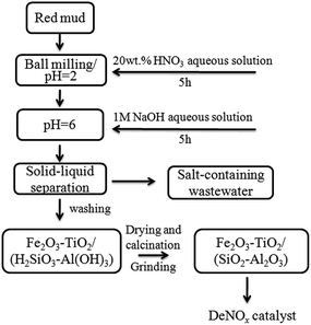 | ||
| Fig. 1 Schematic diagram for preparation of the RM-based catalyst by the ball milling and acid–base neutralization method. | ||
The supported Fe2O3 catalysts on different supports (SiO2, Al2O3, TiO2, and their physical mixtures) were prepared by the conventional incipient wetness impregnation method using ferric nitrate as an iron source. Moreover, the VWTi catalyst without inactive additives was prepared by mixing ammonium metavanadate, ammonium metatungstate, and TiO2 powder with 30 wt% water to form a uniform sludge. All samples were dried for 10 h at 120 °C, and calcined for 3 h at 550 °C to obtain corresponding catalysts.
2.3 Catalytic test
Catalytic activity measurements for SCR of NO by NH3 were conducted in a quartz fixed bed reactor of 11.5 mm in internal diameter under atmospheric pressure. In the present work, the tested catalyst was crushed with particle sizes of 0.3–0.4 mm. The feed gas consisted of 500 ppm NO, 500 ppm NH3, 500 ppm SO2, 5% O2, and 10 vol% H2O balanced with N2. The total flow rate through the reactor was kept at 6 L min−1 (STP) to give a Gas Hourly Space Velocity (GHSV) of 60![[thin space (1/6-em)]](https://www.rsc.org/images/entities/char_2009.gif) 000 h−1. Measurements were performed at fixed temperatures per 50 °C from 300 to 450 °C and kept for 60 min at each stage. Feed and product concentrations were continually monitored using a Horiba PG250 on-line flue gas analyzer (Horiba, Kyoto, Japan). The NO conversion was calculated according to measured inlet and outlet NO concentrations.
000 h−1. Measurements were performed at fixed temperatures per 50 °C from 300 to 450 °C and kept for 60 min at each stage. Feed and product concentrations were continually monitored using a Horiba PG250 on-line flue gas analyzer (Horiba, Kyoto, Japan). The NO conversion was calculated according to measured inlet and outlet NO concentrations.
2.4 Sample characterization
Chemical compositions of RM-based samples were determined with an Axios X-ray fluorescence (XRF) spectrometer (PANalytical X'pert, Almelo, Netherlands). Their X-ray diffraction (XRD) patterns were obtained in the range of 2θ from 10° to 90° on a D/Max-RB diffractometer (Rigaku Corp., Tokyo, Japan) with Cu Kα radiation. Nitrogen adsorption/desorption isotherms were recorded on an ASAP 2020 (Micromeritics Instrument Corp., Norcross, USA) at 77 K. The Brunauer–Emmett–Teller (BET) equation was used to calculate the specific surface area (SBET), and pore size distributions were calculated from the adsorption branch using the Barret–Joyner–Halenda (BJH) model. Composition and oxidation states of the elements were recorded by X-ray photoelectron spectroscopy (XPS) with an ESCALAB 250Xi electron spectrometer from Thermo Fisher Scientific Corp. (New York, USA). Reported binding energy values were all corrected by referring to the binding energy of C 1s, that is, 284.8 eV. Morphology of RM-based samples was observed using JSM-7001F scanning electron microscopy (SEM, JEOL Ltd., Tokyo, Japan) at an accelerating voltage of 10 kV, and JEM-2100 of JEOL transmission electron microscope (TEM) at 200 kV, respectively. Formation of surface sulfate species was investigated by thermogravimetry (TG) measurements that were carried out on an Exstar TG/DTA 7300 (Seiko Instrument Inc., Tokyo, Japan) under argon atmosphere and a heating rate of 20 °C min−1 from 30 °C to 1000 °C.NH3-TPD and H2-TPR experiments were performed on an AutoChem II-2920s V5.02 from Micromeritics Instrument Corp. (Norcross, USA). First, 0.1 g of sample was loaded in a quartz U-tube and heated from room temperature to 300 °C at 10 °C min−1, maintained for 60 min in helium atmosphere, and cooled to room temperature. After pre-absorption of 10 vol% NH3 for 60 min and purging with He for 30 min at room temperature, the NH3-TPD test was performed by heating the samples to 750 °C at 10 °C min−1 in He atmosphere. For the H2-TPR test, the pre-processing sample was heated to 1000 °C at 10 °C min−1 in 10 vol% H2 atmosphere. Released NH3 and H2 were detected continuously by a TCD detector. All the flow rates in this experiment were 50 mL min−1.
In situ DRIFTS experiments were performed on a FTIR spectrometer (Bruker, Tensor 27) equipped with a Harrick DRIFT cell containing ZnSe/KBr windows and a MCT detector. Prior to each experiment, the sample was pre-treated at 500 °C for 1 h in a flow of nitrogen. The background spectrum was collected in flowing nitrogen at 30, 100, 200, 300, 350, and 400 °C, respectively. For the desorption test, the sample was exposed in the flow of NH3 (or NO + O2) for 20 min, purged by nitrogen for 40 min at 30 °C, and then heated to the target temperature of 30, 100, 200, 300, 350, and 400 °C for 20 min to record the spectrum, respectively. In the transient studies, the catalyst was first pre-exposed to a flow of NH3 (or NO + O2) for 20 min, then purged with nitrogen for 40 min at 350 °C, subsequently in the flow of NO + O2 (or NH3) to get the time dependent changes of the DRIFT spectra. All IR spectra were obtained by collecting 50 scans with a resolution of 4 cm−1.
3. Results and discussion
3.1 The performance of RM-based catalysts
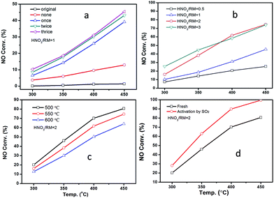
Fig. 2 displays the NH3-SCR performance of RM-based catalysts after different treatments. It can be observed from Fig. 2A that the original RM sample shows nearly no denitration activity even at 450 °C. After being treated by HNO3 with a HNO3/RM ratio of 1, the RM sample becomes active for the NH3-SCR reaction with above 45% NO conversion. Increased washing times can promote catalytic activity. The close activity curves for the washed-twice/thrice samples indicate that washing two times will be enough to remove the poisonous elements to a level useful for the SCR reaction. The optimization of HNO3/RM ratio was also investigated in our work. As shown in Fig. 2B, an increase of HNO3/RM ratio to 2 can notably improve the catalytic activity with a 75% NO conversion at 450 °C, but the increase of HNO3/RM ratio to 3 only exerts a slight promotion effect for DeNOx activity at low temperature. The study of calcination temperature for the treated RM sample (Fig. 2C) manifests that catalytic activity increases with reduced calcination temperature and the sample calcinated at 500 °C has the best activity with 80% NO conversion. Most remarkably, it can be found that the activation of RM catalyst by SO2 can significantly improve the NO conversion close to 100% above 400 °C (Fig. 2D). In addition, N2O was also detected during the catalytic test as shown in Fig. S1.† It can be seen that the increased washing times, high ratio of HNO3/RM, and low calcination temperature can lower the generation of N2O and increase DeNOx selectivity. In brief, by treating the original RM waste through nitric acid digestion, washing, and activation processes, the RM waste can be used as a low cost and effective denitration catalyst at high temperature.As a comparison, the DeNOx performances of supported Fe2O3 catalysts on different supports (SiO2, Al2O3, TiO2, and their physical mixture) are shown in Fig. S2A.† It can be seen that the activity follows the order of Fe2O3/SiO2 < Fe2O3/Al2O3 < Fe2O3/SiO2–Al2O3–TiO2 < Fe2O3/TiO2, indicating the merit of the composite support. However, the activity of RM catalysts is even comparable with the Fe2O3/TiO2 catalyst, which may result from the homogeneity of composite oxides in chemical levels.
In real flue gas, high contents of SO2 and H2O may have a great effect on the catalytic activity. The impact of SO2 and H2O was studied as shown in Fig. 3. The introduction of SO2 and H2O can notably decrease the catalytic activity for both RM-based catalyst and commercial vanadium-based catalyst under GHSV at 60![[thin space (1/6-em)]](https://www.rsc.org/images/entities/char_2009.gif) 000 h−1 (Fig. 3a). The VWTi catalyst, without inactive additives as comparison, is also exhibited in Fig. S2B.† Notably, although the vanadium based catalyst has better denitration activity at a medium temperature range of 300–350 °C, the RM-based catalysts have comparable, or even high catalytic activity, at a high temperature range above 350 °C. The results demonstrate the great advantage of a RM-based catalyst for its application in the denitration of high-temperature flue gas. Moreover, the stability of RM-based catalyst was further investigated in different gas compositions as shown in Fig. 3b at the temperature of 450 °C. After 500 ppm SO2 and 10% H2O is introduced, the NO conversion reduces about ten percentage point, but can maintain stable catalytic activity even with 1000 ppm SO2 and 10% H2O. It is interesting that cutting off SO2 can't recover the catalytic activity, but simultaneously cutting off H2O will have the same NO removal efficiency as with the initial value. These results show that the catalytic activity of RM catalyst was mainly inhibited by H2O in the flue gas, which should be a result from the competitive adsorption of H2O on active sites. The demonstrated stability of the RM-based catalyst implies its promising application prospects for purification of real flue gas.
000 h−1 (Fig. 3a). The VWTi catalyst, without inactive additives as comparison, is also exhibited in Fig. S2B.† Notably, although the vanadium based catalyst has better denitration activity at a medium temperature range of 300–350 °C, the RM-based catalysts have comparable, or even high catalytic activity, at a high temperature range above 350 °C. The results demonstrate the great advantage of a RM-based catalyst for its application in the denitration of high-temperature flue gas. Moreover, the stability of RM-based catalyst was further investigated in different gas compositions as shown in Fig. 3b at the temperature of 450 °C. After 500 ppm SO2 and 10% H2O is introduced, the NO conversion reduces about ten percentage point, but can maintain stable catalytic activity even with 1000 ppm SO2 and 10% H2O. It is interesting that cutting off SO2 can't recover the catalytic activity, but simultaneously cutting off H2O will have the same NO removal efficiency as with the initial value. These results show that the catalytic activity of RM catalyst was mainly inhibited by H2O in the flue gas, which should be a result from the competitive adsorption of H2O on active sites. The demonstrated stability of the RM-based catalyst implies its promising application prospects for purification of real flue gas.
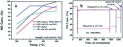 | ||
| Fig. 3 The activity comparison between SO2-activated RM and commercial DF catalysts (a), and catalytic stability of RM catalysts with/without SO2 and H2O at 450 °C (b). | ||
3.2 Composition and structure of RM-based catalysts
To better understand the above excellent denitration activity of the RM-based catalysts, their basic compositions and structures were studied and are reported in detail here. Table 1 shows XRF results of the different RM samples. In the original RM, the main components are Fe2O3 (37.87 wt%), Al2O3 (24.02 wt%), SiO2 (16.65 wt%), and TiO2 (7.63 wt%), which exactly constitute the active component (iron oxide) and supports a denitration catalyst. However, the original sample has very high Na2O content (11.16 wt%) and other alkaline-earth metals, such as CaO and MgO, which can severely poison and inactivate the denitration catalyst. Acid treatment of RM and the subsequent washing process dramatically decreases the alkali metal to a very low level. Increased washing times from none to thrice gradually decreased the alkali oxides contents, but the amount of alkaline earth oxides still maintained a high value after washing more than two times for the cases of HNO3/RM ratios at 0.5 and 1. As the HNO3/RM ratio goes above 1, the content of both of alkali oxides and alkaline earth oxides decreases greatly to a very low level. These results manifest that the alkali/alkaline-earth metal elements can be removed to a limit with the HNO3/RM ratio exceeding 1 after washing above two times, which should eliminate the poisoning effect of alkali/alkaline-earth metal elements on catalytic activity for NH3-SCR reactions.| Samples | Fe2O3 | Al2O3 | SiO2 | TiO2 | Na2O | CaO | K2O | MgO |
|---|---|---|---|---|---|---|---|---|
| Original | 37.87 | 24.02 | 16.65 | 7.63 | 11.16 | 1.24 | 0.09 | 0.11 |
| Washed-none | 41.54 | 24.63 | 16.47 | 7.95 | 6.74 | 1.59 | 0.06 | 0.12 |
| Washed-once | 44.00 | 26.83 | 17.80 | 8.45 | 0.51 | 1.35 | 0.05 | 0.09 |
| Washed-twice | 44.97 | 25.69 | 18.13 | 8.82 | 0.36 | 0.97 | 0.04 | 0.09 |
| Washed-thrice | 44.98 | 25.99 | 17.97 | 8.70 | 0.36 | 0.97 | 0.05 | 0.08 |
| HNO3/RM = 0.5 | 44.72 | 26.36 | 17.29 | 8.51 | 0.60 | 0.99 | 0.18 | 0.10 |
| HNO3/RM = 1 | 44.98 | 25.99 | 17.97 | 8.70 | 0.36 | 0.97 | 0.05 | 0.08 |
| HNO3/RM = 2 | 44.96 | 26.02 | 16.07 | 7.75 | 0.13 | 0.35 | 0.04 | 0.07 |
| HNO3/RM = 3 | 44.42 | 25.51 | 16.10 | 7.79 | 0.12 | 0.36 | 0.04 | 0.10 |
The XRD patterns in Fig. S3† demonstrate that all the RM samples have their main diffraction peaks at 24.2, 33.3, 35.8, 41.2, 49.8, 54.2, 62.7, and 64.2° belonging to hematite (Fe2O3) phase (JCPDS 33-0664). Anatase TiO2 can also be observed at 25.5 and 48.1° according to JCPDS 21-1272. The original RM sample (Fig. S3a†) has a notable diffraction peak at 14.0°, which can be assigned to zeolite-like sodium silicoaluminate (JCPDS 40-0101). After acid treatment without washing (Fig. S3b†), the sodium salt is converted to albite sodium silicoaluminate at 28.1° (JCPDS 10-0393). And this peak disappeared after the washing process or increased HNO3/RM ratio (Fig. S3c–f†), indicating the cleaning of sodium element in RM samples after the acid treatment and washing process. Meanwhile, no silicon and aluminium oxide species are observed in the XRD patterns in Fig. S3,† indicating they are in the amorphous form. In addition, the increased calcination temperature will not cause an obvious change in RM samples (Fig. S3g and h†). The shown structure transformation of different RM samples is well consistent with the composition change of XRF data in Table 1. In combination with the catalytic results in Fig. 1, it can be concluded that the elimination of alkaline elements by the acid treatment and washing process makes the RM waste active for NH3-SCR reactions.
The morphology features of these RM samples were characterized by SEM and TEM as shown in Fig. 4. In the case of the original RM sample, many bulky grains can be observed with a micron grade size (Fig. 4A and B). After the acid treatment and washing process, the particles of the RM samples become more dispersed in a nanoscale range of 50–800 nm (Fig. 4C). High resolution TEM can clearly observe the lattice fringe phase of α-Fe2O3 (104) crystal face with the lattice distance of 0.27 nm (Fig. 4D), which is in accord with the XRD results in Fig. S3.† For a sufficiently SO2 activated sample, the particles become much smaller than the corresponding fresh sample (Fig. S3E†). Moreover, the lattice fringe phase of Fe2(SO4)3 (113) crystal face with a lattice distance of 0.36 nm is observed except with the α-Fe2O3 phase, indicating the conversion of part α-Fe2O3 to Fe2(SO4)3 after the activation by SO2.
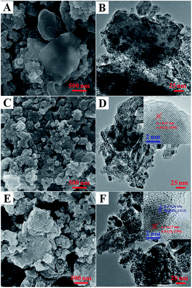 | ||
| Fig. 4 SEM and TEM images of the original RM sample (A, B), the typical fresh RM catalyst (C, D), and the SO2-activated RM catalyst (E, F) together with their high resolution TEM images (the insert). | ||
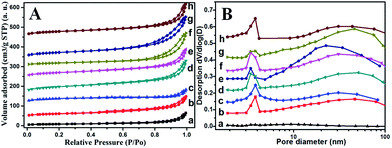
To have deep insight into the change of surface area and pore-size distribution after treatment, a BET test was performed. Fig. 5 displays the N2 adsorption–desorption isotherm and the corresponding pore size distribution curve for different RM samples. All the samples exhibit the typical IV isotherm with a H3-type hysteresis loop (P/P0 > 0.4), indicating the mesoporous characteristics of these RM-based catalysts (Fig. 5A).10 In combination with the quantitative data summarized in Table 2, it can be found that the acid treatment and washing process has great impact on surface area and pore-size distribution. The surface area is as low as 26.8 m2 g−1 for the original RM. In contrast, the acid treatment and washing process can dramatically increase their surface area with a maximum of 134.1 m2 g−1 as the ratio of HNO3/RM increased to 2, which may derive from an increased dispersity of the amorphous silicon and aluminium oxide species. But the further elevated HNO3/RM ratio to 3 inversely decreased the value of the surface area. Moreover, elevating the calcination temperature to 600 °C decreased the BET area owing to the sintering of RM particles. The mesoporous features are shown in Fig. 5B. The original RM has few pores with a very small pore volume (0.09 cm2 g−1). The acid treatment and washing process results in a pore distribution between 1 and 10 nm and 10–100 nm with obviously increased pore volume. Similarly, with the change of BET area, the pore volume increases to its maximum value (0.32 cm2 g−1) at a HNO3/RM ratio of 2 and then decreases. The increased calcination temperature at 600 °C also decreases the pore volume but the washing process can remarkably increase it.
| Samples | BET surface areas (m2 g−1) | Pore volume (cm3 g−1) | Pore size (nm) |
|---|---|---|---|
| Original | 26.8 | 0.09 | 19.5 |
| HNO3/RM = 0.5 | 69.5 | 0.14 | 10.6 |
| HNO3/RM = 1, washed-none | 65.2 | 0.16 | 13.3 |
| HNO3/RM = 1, washed-twice | 113.8 | 0.23 | 17.5 |
| HNO3/RM = 2 | 134.1 | 0.32 | 9.6 |
| HNO3/RM = 2, 600 °C | 106.3 | 0.22 | 9.8 |
| HNO3/RM = 2, SO2 activated | 127.2 | 0.20 | 10.4 |
| HNO3/RM = 3 | 101.1 | 0.25 | 12.6 |
As shown by the above XRF and XRD results, the original RM sample is mainly composed of Fe2O3, TiO2, and aluminum silicate sodium. The added HNO3 can dissolve part of the Fe2O3 and aluminum silicate sodium, and the subsequent neutral reaction by NaOH forms a colloidal turbid liquid as observed during the preparation process. The colloidal turbid liquid may contain ferric hydroxide, alumina/silica sol, and undissolved TiO2 and other RM components. Meanwhile, alkali/alkaline-earth metal elements are released and eliminated by the washing process. The RM-based catalysts are obtained by drying the colloidal turbid liquid and following the calcination process. Based on the physicochemical change during the preparation process, the increased BET area and abundant pore structure of RM-based catalysts can be attributed to dissolution and precipitation of RM constituents during the acid–alkali treatment process. On the other hand, the release of sodium element from aluminum silicate salt may also contribute to increasing the surface area and enriching the pore structure. But too much HNO3 may destroy the skeletal aluminum silicate structure, resulting in the decreased BET area and pore volume. The calcination at high temperature enhances the agglomeration of RM particles and also decreases the surface area and pore volume. Most notably, the catalytic activity in Fig. 2 is highly relevant to the BET area of RM samples listed in Table 2, revealing that the dispersion of RM particles is another key factor to determine their catalytic activity. For a SO2 activated sample, although it has a slightly decreased BET area and pore structure compared with its fresh sample, its activity still improved significantly as shown in Fig. 2D. The reason will be discussed in the following text.
For a better understanding of the significant promotion effect of SO2 activation on the catalytic performance of RM-based catalysts, detailed structures of the activated catalysts were studied by TG, XRD, and XPS analysis. For the TG results in Fig. 6A, the fresh RM sample has no weight lost above 200 °C. But the SO2 activated catalyst shows 7.6 wt% weight lost between 550 °C and 700 °C, which can be assigned to be the decomposition of Fe2(SO4)3 in contrast with the TG curve of pure Fe2(SO4)3. Correspondingly, its XRD patterns show an extra small peak at 24.8° compared with the fresh one (Fig. 6B), which can be assigned to the Fe2(SO4)3. These results are quite consistent with the lattice fringe phase of Fe2(SO4)3 observed by HRTEM. These evidences readily confirm the formation of an Fe2(SO4)3 phase on the surface of RM-based catalysts after activation by SO2. Moreover, the formation of Fe2(SO4)3 also changes the XPS signals as shown for Fe 2P and S 2p spectrogram in Fig. 5C and D. Fresh RM catalyst exhibits the Fe 2p1/2 and 2p3/2 signals at 712.5 eV and 724.8 eV, respectively, which can be assigned to Fe2O3.11 The corresponding Fe 2p peak for the SO2 activated catalyst obviously moves towards high binding energy about 0.2 eV, owing to the more polarized electron feature in Fe2(SO4)3 than Fe2O3. Compared with the fresh sample, a strong S 2p XPS signal is detected for a SO2 activated RM sample, which can also evidence the existence of sulfate species. In consideration of the significantly increased catalytic activity for the SO2 activated RM catalyst in Fig. 2 and some literature reports,12 the generated Fe2(SO4)3 species may form new active sites in the RM catalyst for the NH3-SCR reaction.
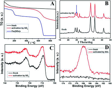 | ||
| Fig. 6 The TG (A), XRD (B), Fe 2p XPS (C) together with the S 2p XPS (D) data of the fresh and SO2-activated RM catalysts. | ||
In brief, it can be concluded that the clearing of alkali/alkaline-earth metal elements in the original RM sample by the ball milling and acid–base neutralization method can eliminate their poisoning effect and thus makes the RM waste active for the denitration reaction. Meanwhile, increased particle dispersion and BET area of RM by a proper HNO3/RM ratio and calcination temperature can improve their catalytic activity by exposing more active sites. In addition, formation of Fe2(SO4)3 for the SO2-activated catalyst will serve as a new active species and further enhance its denitration activity.
3.3 Adsorption/reaction features of catalytic active sites
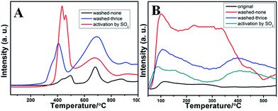
Temperature programmed desorption of ammonia (NH3-TPD) experiments were further carried out to evaluate the acidity of RM-based catalysts as shown in Fig. 7B. It can be seen that the adsorption capacity of NH3 increases significantly for the treated RM sample compared with the original one, which may result from the strong active acid sites on the surface of amorphous silicon and aluminum oxides after acid treatment. All the three samples (washed-none, washed-thrice, and SO2 activated) exhibit the NH3 desorption peaks at 100 °C and 380 °C, respectively. For the washed-thrice sample, the NH3 adsorption capacity obviously increases compared with the washed-none sample owing to the elimination of alkaline elements. Moreover, NH3 adsorption capacity of the SO2 activated sample increases dramatically for both the low and high temperature peaks, indicating increased acidity derived from the generation of ferric sulfate species. As the main reaction molecule, the NH3 desorption features will have great impact on their catalytic behavior as discussed in the following text.
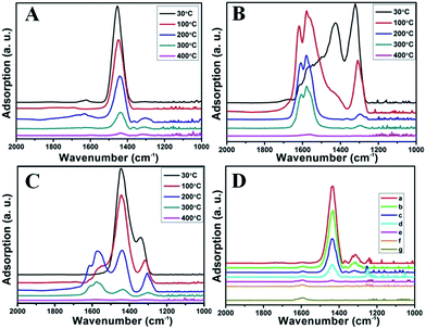
Fig. 8B illustrates the DRIFT desorption spectra of NO + O2 on the RM catalyst at different temperatures. Several distinct peaks appear at 1610, 1580, 1555, 1425, and 1322 cm−1, which can be ascribed to adsorbed NO2 (1610 cm−1), bidentate nitrate (1580 cm−1), monodentate nitrate (1554 cm−1), linear nitrate (1425 cm−1), and M–NO2 nitro species (1322 cm−1), respectively.17–20 From 30 to 100 °C, the linear nitrate (1425 cm−1) and M–NO2 (1322 cm−1) get weak together with the increase of strongly adsorbed NO2 (1610 cm−1) and bidentate nitrate (1580 cm−1). These results imply the easy oxidation of NO by O2 to NO2 on RM catalyst at low temperatures, which is a key step for the “fast SCR” reaction.21 As the temperature increased, the NO2 (1610 cm−1) and bidentate nitrate (1580 cm−1) were rapidly desorbed and little adsorbed species are observed at 400 °C.
Fig. 8C shows the co-desorption curves of NH3 and NO + O2 over the RM catalyst at different temperatures. Compared with the independent desorption of NH3 and NO + O2, the adsorbed NO2 (1610 cm−1) decreased dramatically from 30 to 300 °C, indicating the reaction of adsorbed NO2 and NH3 species through a “fast SCR” route to reduce the generated NO2.21–23 However, the surface species of bidentate nitrate (1580 cm−1) from absorbed NO and NH4+ (1440 cm−1) from absorbed NH3 simultaneously exist on the RM catalyst from 200 to 300 °C. Generally, the NH3 SCR may follow a Langmuir–Hinshelwood or Eley–Rideal mechanism as follows, in which M is the metal active site.6,24–26 Based on the Langmuir–Hinshelwood mechanism, the results clearly reveal that the RM catalysts are very inactive for a NH3-SCR reaction through the Langmuir–Hinshelwood mechanism at relatively low temperatures (<300 °C). In combination with the TPR results in Fig. 7A, the low activity may be due to the difficult conversion for Fe3+/Fe2+ active sites below 300 °C. The further increase of temperature to 400 °C removed all the absorbed species by desorption or inter-reaction.
The Langmuir–Hinshelwood mechanism:
The Eley–Rideal mechanism:
To further make clear the reaction mechanism of RM-based catalysts at high temperature, more DRIFT spectra were collected to observe the reaction details at 350 °C in Fig. 8D. The relatively high temperature of 350 °C was chosen to avoid the interference of low signal to noise ratio owing to the weak absorbed signal at a high temperature. Fig. 8D(a–f) presents the time-dependent changes of the in situ DRIFT spectra of the RM catalyst in a flow of NO and O2 after the catalyst was pre-exposed to a flow of NH3 at 350 °C. A strong peak assigned to absorbed NH4+ can be clearly seen at 1440 cm−1 after being pre-exposed to a flow of NH3 at 350 °C (Fig. 8D(a)). Notably, the absorbed NH4+ disappeared gradually but very fast (within 5 min) after the introduction of NO + O2 over the NH3 pre-exposed catalyst (from Fig. 8D(b–f)), which shows the fast reaction rate between absorbed NH4+ and the introduced NO + O2. On the other hand, little surface species can be observed after pre-exposure of the catalyst over NO + O2 flow at 350 °C (Fig. 8D(g)), suggesting a very weak absorption of NO on the catalytic surface at 350 °C. According to the Eley–Rideal mechanism, NH3 is first absorbed on the acid sites and then reacts with the gaseous NO. These comparative results clearly demonstrate that the NH3-SCR reaction over RM catalyst follows the Eley–Rideal reaction mechanism above 350 °C, whose reaction scheme is shown in Scheme S1.† In the reaction mechanism, NH3 is absorbed to form NH4+ species on acid sites, then interact with the Fe3+ based redox sites, and further capture gaseous NO to generate N2 and H2O. Meanwhile, the Fe3+ species is converted to its Fe2+ state and then recovered by reaction with gaseous O2 to finish the catalytic cycle. Moreover, it can be seen that absorption of NH3 and conversion between Fe3+ and Fe2+ will play the key role in catalytic efficiency at high temperatures.
In brief, both NH3 and NO have strong absorption on the RM catalytic surface below 300 °C. The difficult conversion for Fe3+/Fe2+ at low temperatures may prevent the reaction of co-absorption NH3 and NO species following the Langmuir–Hinshelwood mechanism, but the NH3-SCR may still react slowly through the “fast SCR” route owing to the generation of absorbed NO2. But at the high temperature of 350 °C, only NH3 species (but not NO) are absorbed on the catalytic surface and react with gaseous NO and O2, confirming that the high-temperature SCR reaction follows the Eley–Rideal mechanism over RM catalysts. The absorbed NH3 plays a key role in the Eley–Rideal mechanism. The high catalytic activity for RM catalyst at high temperatures is due to the strong and abundant acid sites together with the easy conversion for Fe3+/Fe2+ active sites on the catalytic surface.
4. Conclusions
In summary, this work demonstrates the successful reusage of RM waste as effective catalysts for a high-temperature NH3-SCR reaction by the ball milling and acid–base neutralization method, whose activity can further be enhanced by SO2 activation. The resulting RM-based catalysts have comparable catalytic activity and stability with the commercial V–W–Ti catalyst above 350 °C in the presence of SO2 and H2O. Structure characterization data (XRF, XRD, SEM, TEM, BET, XPS, TG, and H2-TPR) reveal that the eliminated poisonous alkaline metal elements together with the increased dispersion of RM particles make RM waste active for a denitration reaction, and the formation of ferric sulfate species with more reducible Fe3+/Fe2+ active sites by the SO2 activation process can further enhance their denitration activity. The study by NH3-TPD and in situ IR further demonstrates that the NH3-SCR reaction over the RM-based catalyst follows the Eley–Rideal mechanism at high temperatures and the absorption of NH3 plays a key role in catalytic performance. The elimination of alkaline metal elements and SO2 activation process increases the absorption of NH3 and thus the DeNOx activity. The demonstrated reusage of RM waste as effective DeNOx catalysts in this work will possess great application prospects for both resource utilization of RM waste and development of low cost DeNOx catalysts.Conflicts of interest
There are no conflicts to declare.Acknowledgements
The authors are grateful for the financial support of Science and Technology Service Network Initiative of China (KFJ-SW-STS-149), International Science and Technology Cooperation Program of China (2016YFE0128300), Natural Science and Foundation of China (Grant 21601192) and Postdoctoral Fellowship of Japan Society for the Promotion of Science (JSPS by P15758).Notes and references
- H. Chen, G. Wang, Y. Xu, Z. Chen and F. Yin, RSC Adv., 2016, 6, 54202–54214 RSC.
- J. Li, L. Xu, P. Sun, P. Zhai, X. Chen, H. Zhang, Z. Zhang and W. Zhu, Chem. Eng. J., 2017, 321, 622–634 CrossRef CAS.
- Y. Huang, W. Chai, G. Han, W. Wang, S. Yang and J. Liu, J. Hazard. Mater., 2016, 307, 318–327 CrossRef CAS PubMed.
- Z. P. Hu, H. Zhao, Z. M. Gao and Z. Y. Yuan, RSC Adv., 2016, 6, 94748–94755 RSC.
- R. Li, T. Zhang, Y. Liu, G. Lv and L. Xie, J. Hazard. Mater., 2016, 316, 94–101 CrossRef CAS PubMed.
- M. Jablonska and R. Palkovits, Catal. Sci. Technol., 2016, 6, 49–72 Search PubMed.
- S. Yang, J. Li, C. Wang, J. Chen, L. Ma, H. Chang, L. Chen, Y. peng and N. Yan, Appl. Catal., B, 2012, 117–118, 73–80 CrossRef CAS.
- B. Li, Z. Huang, X. Huang, S. Kou, F. Liu, X. Zhang and H. Yang, RSC Adv., 2016, 6, 6300–6307 RSC.
- W. Gu, M. Zhou, W. Ma and Y. Wang, Chem. Ind. Eng. Prog., 2012, 31, 1493–1500 CAS.
- S. Li, H. Wang, W. Li, X. Wu, W. Tang and Y. Chen, Appl. Catal., B, 2015, 166–167, 260–269 CrossRef CAS.
- M. Casanova, L. Nodari, A. Sagar, K. Schermanz and A. Trovarelli, Appl. Catal., B, 2015, 176–177, 699–708 CrossRef CAS.
- L. Ma, J. Li, R. Ke and L. Fu, J. Phys. Chem. C, 2011, 115, 7603–7612 CAS.
- G. Wu, J. Li, Z. Fang, L. Lan, R. Wang, T. Lin, M. Gong and Y. Chen, Chem. Eng. J., 2015, 271, 1–13 CrossRef CAS.
- S. Yang, C. Liu, H. Chang, L. Ma, Z. Qu, N. Yan, C. Wang and J. Li, Ind. Eng. Chem. Res., 2013, 52, 5601–5610 CrossRef CAS.
- L. Lietti, J. L. Alemany, P. Forzatti, G. Busca, G. Ramis, E. Giamello and F. Bregani, Catal. Today, 1996, 29, 143–148 CrossRef CAS.
- Z. Liu, Y. Liu, B. Chen, T. Zhu and L. Ma, Catal. Sci. Technol., 2016, 6, 6688–6696 CAS.
- L. Chen, J. Li and M. Ge, Environ. Sci. Technol., 2010, 44, 9590–9596 CrossRef CAS PubMed.
- M. Machida, M. Uto, D. Kurogi and T. Kijima, Chem. Mater., 2000, 12, 3158–3164 CrossRef CAS.
- F. Liu, H. He, Y. Ding and C. Zhang, Appl. Catal., B, 2009, 93, 194–204 CrossRef CAS.
- C. N. Costa and A. M. Efstathiou, J. Phys. Chem. B, 2004, 108, 2620–2630 CrossRef CAS.
- M. Iwasaki and H. Shinjoh, Appl. Catal., A, 2010, 390, 71–77 CrossRef CAS.
- T. Du, H. Qu, Q. Liu, Q. Zhong and W. Ma, Chem. Eng. J., 2015, 262, 1199–1207 CrossRef CAS.
- X. Shi, F. Liu, L. Xie, W. Shan and H. He, Environ. Sci. Technol., 2013, 47, 3293–3298 CrossRef CAS PubMed.
- X. Lei, L. Wang, X. Zhao, Z. Chang, M. Jiang, D. Yan and X. Sun, Ind. Eng. Chem. Res., 2013, 52, 17934–17940 CrossRef CAS.
- B. Thirupathi and P. G. Smirniotis, Appl. Catal., B, 2011, 110, 195–206 CrossRef CAS.
- G. Busca, L. Lietti, G. Ramis and F. Berti, RSC Adv., 2017, 7, 26226–26242 RSC.
Footnote |
| † Electronic supplementary information (ESI) available. See DOI: 10.1039/c7ra10348d |
| This journal is © The Royal Society of Chemistry 2017 |

