 Open Access Article
Electrospun polyacrylonitrile nanofiber mat protected membranes for vanadium flow batteries
Lihong Yu *a,
Feng Lina,
Ling Xua and
Jingyu Xi
 *b
*b
aSchool of Applied Chemistry and Biological Technology, Shenzhen Polytechnic, Shenzhen 518055, China. E-mail: yulihong@szpt.edu.cn
bInstitute of Green Chemistry and Energy, Graduate School at Shenzhen, Tsinghua University, Shenzhen 518055, China. E-mail: xijy@tsinghua.edu.cn
First published on 29th November 2017
Abstract
A cheap, efficient and durable proton exchange membrane is essential for vanadium flow batteries (VFB). The sulfonate poly(ether ether ketone) (SPEEK) membrane is a leading candidate to replace the widely used Nafion series membranes because of high proton to vanadium ion selectivity and low-cost. However, poor chemical/mechanical stability still hinders the practical application of the SPEEK membrane in VFB. Herein, we report a simple and robust strategy by using an electrospun polyacrylonitrile (PAN) nanofiber mat as a protection layer to improve the stability of the SPEEK membrane. The PAN nanofiber mat can prevent the damage to the SPEEK membrane from the vanadium electrolytes, graphite (carbon) felt electrodes and sealing gaskets, without affecting the VFB performance. Therefore, the PAN nanofiber mat–SPEEK–PAN nanofiber mat (P–S–P) sandwich membrane demonstrates excellent rate performance and superior cycling stability over 1000 charge/discharge cycles at a current density of 120 mA cm−2.
1. Introduction
Development of large-scale, highly efficient energy storage technology is essential for protecting grid security and promoting the use of renewable energy.1–3 Vanadium flow batteries (VFB) have attracted wide attention because of their advantages, such as long cycle life, modular design and flexible operation.4–6 Despite extensive research, there are still significant obstacles to the practical application of VFB.7–9 The major challenges arise from the expensive Nafion membrane and the vanadium ion crossover during charge/discharge.10,11 The former results in high cost ($1000 per kW per h)12–14 and the latter causes low coulombic efficiency (CE) and rapid capacity fading along with electrolyte imbalance in VFB.15–17Most current efforts on VFB are devoted to novel hydrocarbon-based proton exchange membranes (PEMs) to reduce the cost and mitigate the vanadium crossover.9,18–22 Among various types of nonfluoride PEMs, the sulfonate poly(ether ether ketone) (SPEEK) membrane is a leading candidate for VFB, due to its high proton to vanadium ion selectivity and low cost.23,24 However, the degradation caused by the electrolyte and the pressure from the sealing gasket greatly shorten the service life of the SPEEK membrane.22,25 Therefore, it is significant to improve the mechanical durability and chemical stability of the SPEEK membrane to meet the demand of VFB. To accomplish this goal, various strategies have been used, such as incorporating inorganic fillers,26,27 blending with other polymers,28,29 and reinforcing by porous skeletons.30 Compared with above microscopic modification approaches, macroscopic protection is another effective method. In our previous work, we have demonstrated that the cycling stability of the SPEEK membrane can be greatly enhanced by using 3D porous, hydrophilic and particularly stable poly(tetrafluoroethylene) (PTFE) film as a protective layer on both sides.31 This novel sandwich design would thoroughly change the interactions between PEM and electrolytes, electrodes and sealing materials. The resulted PTFE–SPEEK–PTFE sandwich membrane exhibited superior cycling performance over 1000 charge/discharge cycles at 80 mA cm−2 with stable CE (98.5%) and low capacity decay rate (0.059% per cycle).
Although the porous PTFE film protection approach has proved to be effective to enhance the durability of the SPEEK membrane, the relatively high cost ($50 per m2) of the porous PTFE film hinder its practical application in VFB. Therefore, we hope to find cheaper porous structured materials to replace the expensive porous PTFE film. Polyacrylonitrile (PAN) has been utilized in many fields due to its low-cost, good mechanical property and chemical stability.28 For example, PAN has been widely studied as a raw material for electrospinning,32–34 by which the PAN nanofiber mat can be fabricated with tunable fiber size, mat thickness and porosity.
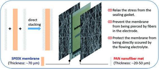
In this study, we use the electrospun PAN nanofiber mat as the protective layer of the SPEEK membrane (denoted as P–S–P), as shown in Fig. 1. The three parts are stacked together by physical contact. The PAN nanofiber mat can prevent the external damage to the SPEEK membrane from the vanadium electrolytes, graphite (carbon) felt electrodes and sealing gaskets. The effect of PAN nanofiber mat on the ion transport properties, VFB rate performance and long-term cycling stability of the SPEEK membrane are studied in detail, and compared with the widely used Nafion 115 membrane. The thickness impact of PAN nanofiber mat on VFB performance of P–S–P membranes is also investigated.
2. Experimental
2.1. Materials
Poly(ether ether ketone) (PEEK 450G) was purchased from Victrex. Polyacrylonitrile (PAN, Mw ∼ 150![[thin space (1/6-em)]](https://www.rsc.org/images/entities/char_2009.gif) 000) was purchased from Sigma-Aldrich. Nafion 115 membrane (Nafion) was purchased from DuPont. PAN based graphite felt (GF, 5 mm of thickness) was purchased from Gansu Haoshi Carbon Fiber Co., Ltd. Other chemicals were of analytical grade and used without further purification.
000) was purchased from Sigma-Aldrich. Nafion 115 membrane (Nafion) was purchased from DuPont. PAN based graphite felt (GF, 5 mm of thickness) was purchased from Gansu Haoshi Carbon Fiber Co., Ltd. Other chemicals were of analytical grade and used without further purification.
2.2. Preparation and characterization of PAN mat
The PAN nanofiber mat was fabricated on an electrospinning instrument (TONGLI TL-01). The electrospinning solution was obtained by dissolving PAN (10 wt%) in DMF at 60 °C under stirring for 10 h, and the flow rate was controlled at 1 mL h−1 by a syringe pump. The detailed electrospun parameters were applied as follow: a high voltage of 15 kV, a needle-to-collector distance of 15 cm, a needle moving speed of 1 cm min−1 within a horizontal range of 10 cm, and a collector rotating speed of 200 rpm. The PAN nanofiber was deposited on an Al foil, which was stuck onto the cylindrical collector. The morphology of the obtained PAN nanofiber mat was observed by scanning electron microscopy (SEM, Hitachi S-4800).2.3. Preparation and characterization of SPEEK membrane
SPEEK membrane was prepared according to our previous work.21 Briefly, 25 g PEEK pellets were sulfonated in 250 mL H2SO4 (98%) at 50 °C for 2.5 h, washed in 0 °C deionized water, and dried at 100 °C. Then, 1.5 g of the obtained SPEEK resin was dissolved in 10 mL DMF solvent to form homogeneous casting solution. Afterwards, the SPEEK solution was cast on glass plate and then dried at 60 °C for 24 h. Finally, the SPEEK membrane was peeled off and then soaked in 1 M H2SO4 and deionized water for 24 h, respectively. The thickness of the SPEEK membrane was 70 μm in wet state, and the degree of sulfonation was 0.61 based on the H+ titration method.31 Vanadium ion crossover of the membrane was measured on a membrane separated diffusion cell,28 and the change of VO2+ concentration was monitored on a UV-vis spectrometer (Leng Guang 752S).2.4. Single cell evaluation
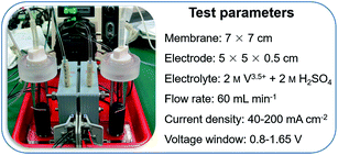
The configuration of a VFB single cell is the same as in our previous work.26,28 The digital photo and detailed parameters of the VFB are listed in Fig. 2. A Nafion 115 membrane (acid boiled)16 and two graphite felts (thermal activated at 420 °C for 10 h)35 were used as separator and electrodes, respectively. The effective area of membrane and electrode is 25 cm2 (5 cm × 5 cm). Two solutions of 50 mL vanadium electrolyte (1 M V3+ + 1 M VO2+ + 2.0 M free H2SO4)36 were used as initial catholyte and anolyte, respectively. Both electrolyte tanks were purged with nitrogen gas for 10 min and then sealed prior to the test. The charge/discharge of the VFB was controlled by a battery testing system (Neware CT-3008-5V6A). The ambient temperature was controlled at 26 ± 2 °C. Rate performance was evaluated under the current densities range from 40 mA cm−2 to 200 mA cm−2. Cycling performance was conducted under the current density of 80 mA cm−2. Super long-term cycling stability was performed at the current density of 120 mA cm−2. The VFB was charged to the 50% state of charge (SOC) at a current density of 60 mA cm−2 to conduct the self-discharge test.3. Results and discussion
Fig. 3a shows the photo of the electrospinning equipment. An Al foil (width = 20 cm) was stuck onto the cylindrical collector to deposit the PAN nanofibers. The average thickness of the PAN nanofiber mat was controlled by tailoring the electrospinning time. For instance, the PAN nanofiber mat with thickness of 20, 40, and 50 μm were obtained at 2, 4, and 5 h of electrospinning, respectively. The obtained PAN nanofiber mat was cut into the size of 7 × 7 cm, the same as that of the SPEEK membrane (Fig. 2), to fabricate the P–S–P sandwich membrane (Fig. 1). As shown in Fig. 3b, the as-prepared PAN nanofiber mat is homogeneous, white and opaque. The fiber morphology of the PAN nanofiber mat was observed by SEM and shown in Fig. 3c and d. The fiber direction is randomly distributed, forming a non-woven porous network structure. Under our electrospinning parameters, the diameter distribution of the nanofiber is very narrow and the average diameter is about 300 nm. In addition, the distance between the PAN nanofibers (1–8 μm) is smaller than the fiber diameter (10–15 μm) in graphite (carbon) felt electrodes.8,31 This ensures that the PAN nanofiber mat protects the SPEEK membrane against the puncturing of the fibers in graphite (carbon) felt electrodes.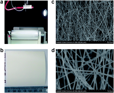 | ||
| Fig. 3 Preparation and characterization of the PAN nanofiber mat: (a) photo of the electrospinning setup, (b) photo of the PAN nanofiber mat, (c and d) SEM images of the PAN nanofiber mat. | ||
The porosity of the PAN nanofiber mat was determined by a simple drainage method since the PAN has excellent hydrophilicity.37 First, the apparent volume (V1) of the PAN nanofiber mat was calculated from its length, width and thickness. Then, the PAN nanofiber mat was immersed into deionized water and evacuated for 1 h to ensure the water thoroughly occupying the fiber gaps of the mat. At last, the volume increase of the measuring cylinder was calculated, which is the actual volume of PAN nanofiber mat (V2). Then, the porosity (P) can be calculated by the equation: P = (V1 − V2)/V1. It is found that the thickness of the PAN nanofiber mat has no obvious relationship with the porosity of the mat. The porosity of all PAN nanofiber mats is about 0.84, which is beneficial to allow the good contact between vanadium electrolyte and SPEEK membrane during VFB operation.
Vanadium ion crossover through the membrane is one of the key problems in VFB, resulting in low CE and rapid capacity fading.9 Therefore, the effect of PAN nanofiber mat (thickness = 20 μm) on the ion transport properties of the SPEEK membrane was evaluated firstly. The widely used Nafion 115 membrane was also tested and used as a benchmark. Fig. 4a shows the VO2+ crossover plots of various membranes. Nafion membrane exhibits very fast VO2+ permeation rate because of the fully opened micellar channels during acid boiling process.10,17 The large size of micellar channels for Nafion membrane will lead to a fast transport of proton and vanadium ions (V2+, V3+, VO2+ and VO2+) simultaneously, resulting in low proton/vanadium ion selectivity. On the contrary, the SPEEK membrane demonstrates extremely low VO2+ permeation rate due to its narrow micellar channels.21,38 After 72 h, the final concentration of VO2+ in the right reservoir of the diffusion cell (inset of Fig. 4a) is 0.168 M and 0.009 M for Nafion and SPEEK membrane, respectively. With the protection of PAN nanofiber mat, the P–S–P sandwich membrane shows slightly lower VO2+ permeation rate than that of pristine SPEEK membrane. This phenomenon may be due to that the PAN nanofiber mat can hold a relatively stable electrolyte layer, which will not be disturbed by the agitation in both reservoirs of the diffusion cell. The same vanadium ion crossover trend is also observed from the self-discharge curves of various membranes, as shown in Fig. 4b. The initial open circuit voltage (OCV) of SPEEK and P–S–P membranes based VFBs is higher than that of the Nafion membrane because of lower permeation rate of vanadium ions during charge process. The OCV values of all VFBs steadily decrease with time before 1.25 V and then drop sharply to 0.8 V, which is due to the disappearance of VO2+ in positive half-cell.16 The time to reach 0.8 V are 36.8 h, 128.1 h and 147.2 h for Nafion, SPEEK and P–S–P membranes, respectively.
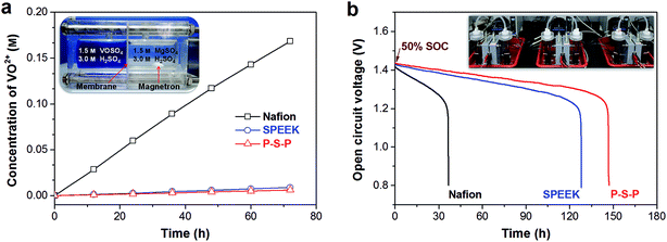 | ||
| Fig. 4 Ion transport properties of various membranes: (a) VO2+ crossover plots, inset shows the photograph of the diffusion cell, (b) self-discharge curves, inset shows the photograph of three VFBs. | ||
All aforementioned membranes were subsequently assembled into VFB single cells to investigate the effect of the PAN nanofiber mat on the SPEEK membrane performances in VFB. The charge/discharge tests were conducted at the current densities range from 40 mA cm−2 to 200 mA cm−2. Fig. 5a illustrates the charge/discharge curves of VFBs with various membranes at a moderate current density of 80 mA cm−2. The VFBs with SPEEK membrane and P–S–P sandwich membrane present nearly the same charge/discharge curves, indicating that the PAN nanofiber mat has no negative effect on the VFB performance of the SPEEK membrane. The theoretical capacity corresponding to 50 mL of 2 M vanadium electrolyte is 2.68 A h. The VFBs with SPEEK and P–S–P membranes can deliver a discharge capacity of 2.36 A h, corresponding to an electrolyte utilization (EU) of 88.1%, significantly higher than that of Nafion membrane (2.20 A h, 82.1% of EU). This is attributed to the lower vanadium permeation rate of SPEEK based membranes compared to the Nafion membrane (Fig. 4). High EU of SPEEK based membranes helps to increase the energy density, which is essential for practical application of VFB.
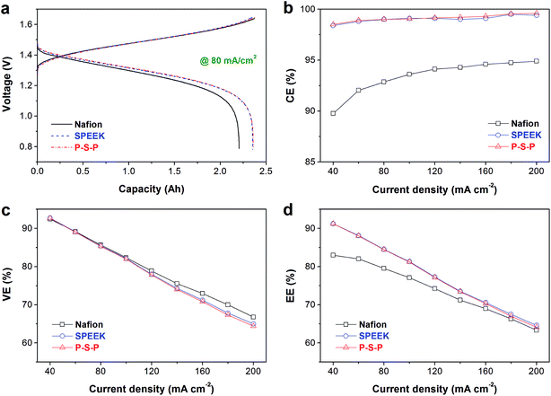 | ||
| Fig. 5 Rate performance of various membranes: (a) charge/discharge curves at 80 mA cm−2, (b) coulombic efficiency, (c) voltage efficiency, (d) energy efficiency. | ||
Rate performance of the VFBs with various membranes, including coulombic efficiency (CE), voltage efficiency (VE) and energy efficiency (EE), are shown in Fig. 5b–d. The CE of Nafion based VFB increases from 89.8% to 94.9% when the current density elevates from 40 mA cm−2 to 200 mA cm−2, due to shorter charge/discharge time at higher current density.16 SPEEK and P–S–P membranes demonstrate very high CE (98.4%) even at a low current density of 40 mA cm−2 because of their extremely low vanadium ion crossover. The P–S–P sandwich membrane does not exhibit the expected higher CE than the SPEEK membrane as compared to the vanadium crossover and self-discharge results in Fig. 4. This may be due to two reasons. On one hand, the SPEEK membrane has already own a high CE value (98.4–99.5% at 40–200 mA cm−2). On the other hand, the electrolyte in the PAN nanofiber mat may be affected by the electric field and mass transfer during charge/discharge process. Therefore, SPEEK and P–S–P membranes exhibit very close CE values at all current densities, as shown in Fig. 5b. The VE of all VFBs decreases with increasing current density because of the increased polarization (Fig. 5c).8,39 The VE of the SPEEK membrane is slightly lower than that of the Nafion membrane when the current density is higher than 100 mA cm−2. This is due to the larger area resistance of the SPEEK membrane than the Nafion membrane (0.87 vs. 0.82 Ω cm2). The P–S–P sandwich membrane shows close VE with the SPEEK membrane in the current densities range of 40–100 mA cm−2, indicating that the PAN nanofiber mat has no influence on the VE of the SPEEK membrane at moderate current densities. However, slightly loss of VE can be observed for the P–S–P sandwich membrane when the current density is higher than 120 mA cm−2, suggesting that the PAN nanofiber mat would affect the mass transfer at higher current densities. With the mutual effect of CE and EE, both the SPEEK and the P–S–P membranes demonstrate higher EE than that of the Nafion membrane at all current densities, although their difference decreases with increasing current density (Fig. 5d). The rate performance results clearly show that the PAN nanofiber mat protective layer has no obvious influence on the battery efficiency of the SPEEK membrane.
To reveal the effect of the thickness of the protective layer on the VFB performance of the SPEEK membrane, a series of P–S–P sandwich membranes with various thickness of PAN nanofiber mat (i.e. 20, 40 and 50 μm) were fabricated and assembled into VFBs. The VFBs were evaluated by charging/discharging at current density of 80 mA cm−2, and the obtained efficiencies are compared in Fig. 6. Obviously, the thickness of the PAN nanofiber mat has almost no influence on CE and EE of the SPEEK membrane. Therefore, the 20 μm thick of PAN nanofiber mat was selected as the protective layer of the SPEEK membrane for subsequent lifespan test.
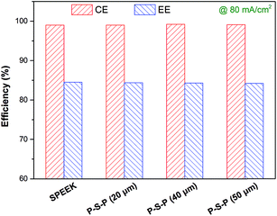 | ||
| Fig. 6 Thickness impact of the PAN nanofiber mat on VFB performance of various P–S–P membranes at a current density of 80 mA cm−2. | ||
Fig. 7 shows the cycling performance of VFBs with Nafion, SPEEK and P–S–P membranes at current density of 80 mA cm−2. The Nafion membrane exhibits stable CE over 200 cycles because of its extremely high mechanical/chemical stability.10,38 However, charge capacity of Nafion membrane decays very fast and the capacity retention is only 22.9% after 200 cycles due to serious vanadium crossover issue.9,16 For the SPEEK membrane, the CE remains stable and the capacity fading is slow in the first 100 cycles, indicating that the SPEEK membrane is relatively stable for short operation time in VFB. In the subsequent 101–154 cycles, the CE reduces gradually and the capacity decays faster, suggesting that the SPEEK membrane began to degrade gradually because of its poor chemical/mechanical stability.25,31 Finally, the CE drops sharply at the 155th cycle, indicating that the SPEEK membrane has ruptured. With the protection of PAN nanofiber mat, the P–S–P sandwich membrane demonstrates extremely stable CE over 300 cycles. Meanwhile, the capacity fading of the P–S–P membrane is much slower than that of the Nafion membrane. For instance, after 200 cycles, the capacity retention of the P–S–P membrane is 79.9%, 57% higher than that of the Nafion membrane. Comparing the capacity decay curves of SPEEK and P–S–P membranes (Fig. 7b), it suggests that the PAN nanofiber mat can indeed protect the SPEEK membrane effectively for the VFB application. For different components of the VFB, the protection mechanism may include three aspects: (1) relax the stress from the sealing gasket; (2) prevent the membrane from being pierced by fibers in graphite (carbon) felt electrode; (3) protect the membrane from being directly scoured by the flowing electrolyte.
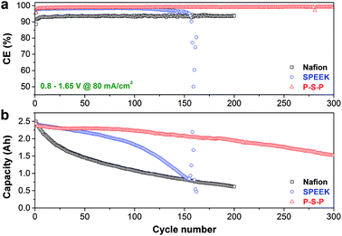 | ||
| Fig. 7 Cycling performance of various membranes at a current density of 80 mA cm−2: (a) coulombic efficiency, (b) charge capacity fading curves. | ||
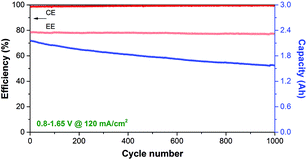
To further assess the durability of the P–S–P membrane, a super long-term charge/discharge test was conducted over 1000 cycles at a high current density of 120 mA cm−2. As shown in Fig. 8, the P–S–P membrane exhibits a high CE (>99%) throughout 1000 cycles, indicating superior durability of the sandwich membrane. The CE increases slightly with the cycle, due to the shorter charge/discharge time with the capacity fading. Meanwhile, the EE declines only 1.3% (from 78.4% to 77.1%) after 1000 cycles, which should be ascribed to the precipitation of V2O5 in the positive half-cell during long-term operation.8,35 Notably, the P–S–P membrane shows excellent capacity retention ability and remains 72.7% of its initial charge capacity even after 1000 cycles, corresponding to an extremely lower capacity decay rate of 0.027% per cycle. The super long-term cycling stability clearly demonstrates that the PAN nanofiber mat protection is an efficient and robust strategy to promote the use of SPEEK membrane in VFB.
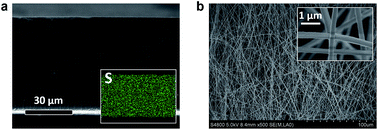
The micro morphology of the P–S–P membrane was analyzed by SEM after above lifespan test. The three parts of the sandwich membrane can be easily separated. As shown in Fig. 9a, the SPEEK membrane shows dense cross-section structure with evenly distributed S element (from –SO3−), suggesting that the SPEEK membrane does not suffer serious damage during long-term operation. The PAN nanofiber mat also remains unchanged fiber morphology (Fig. 9b) as compared with the fresh one (Fig. 3c), indicating the excellent chemical/mechanical stability of PAN fiber in the harsh vanadium electrolyte. This metric is beneficial for the PAN nanofiber mat to protect any other nonfluoride PEMs for highly efficient and durable use in long-life VFB.
4. Conclusions
In summary, a thin layer PAN nanofiber mat was prepared by electrospinning method and used as a protective layer for the SPEEK membrane in VFB. The average fiber diameter, distance between the fibers and porosity of the PAN nanofiber mat is 300 nm, 1–8 μm and 0.91, respectively. To fabricate a P–S–P sandwich membrane, the three parts are stacked together by physical contact. The PAN nanofiber mat can protect the SPEEK membrane through three aspects: (1) relax the stress from the sealing gasket; (2) prevent the SPEEK membrane from being pierced by fibers in the electrode; (3) protect the SPEEK membrane from being directly scoured by the flowing vanadium electrolyte. Meanwhile, the PAN nanofiber mat has no obvious influence on the VFB efficiency of the SPEEK membrane. As a result, the P–S–P sandwich membrane exhibits high electrolyte utilization (88.1%@80 mA cm−2), excellent rate performance (84.4% of EE@80 mA cm−2) and superior durability (>99% of CE over 1000 cycles@120 mA cm−2) for long-term VFB operation. Moreover, this simple and robust protection strategy can be also used to promote other nonfluoride PEMs for VFB.Conflicts of interest
There are no conflicts to declare.Acknowledgements
We acknowledge the financial support from the Shenzhen Basic Research Project (No. JCYJ20150630114140630, JCYJ20170307152754218 and JCYJ20170412170756603) and the Natural Science Foundation of Guangdong Province (No. 2016A030310025 and 2015A030313894).References
- B. Dunn, H. Kamath and J. M. Tarascon, Science, 2011, 334, 928 CrossRef CAS PubMed.
- Z. Yang, J. Zhang, M. C. Kintner-Meyer, X. Lu, D. Choi, J. P. Lemmon and J. Liu, Chem. Rev., 2011, 111, 3577 CrossRef CAS PubMed.
- C. P. Grey and J. M. Tarascon, Nat. Mater., 2017, 16, 45 CrossRef PubMed.
- M. Skyllas-Kazacos, M. Rychcikl, R. G. Robins, A. G. Fane and M. Greens, J. Electrochem. Soc., 1986, 133, 1057 CrossRef CAS.
- M. Ulaganathan, V. Aravindan, Q. Yan, S. Madhavi, M. Skyllas-Kazacos and T. M. Lim, Adv. Mater. Interfaces, 2016, 3, 1500309 CrossRef.
- P. Leung, X. Li, C. P. De León, L. Berlouis, C. J. Low and F. C. Walsh, RSC Adv., 2012, 2, 10125 RSC.
- M. Skyllas-Kazacos, L. Cao, M. Kazacos, N. Kausar and A. Mousa, ChemSusChem, 2016, 9, 1521 CrossRef CAS PubMed.
- K. J. Kim, M. S. Park, Y. J. Kim, J. H. Kim, S. X. Dou and M. Skyllas-Kazacos, J. Mater. Chem. A, 2015, 3, 16913 CAS.
- X. Li, H. Zhang, Z. Mai, H. Zhang and I. Vankelecom, Energy Environ. Sci., 2011, 4, 1147 CAS.
- A. Kusoglu and A. Z. Weber, Chem. Rev., 2017, 117, 987 CrossRef CAS PubMed.
- J. Xi, Z. Wu, X. Qiu and L. Chen, J. Power Sources, 2007, 166, 531 CrossRef CAS.
- R. V. Noorden, Nature, 2014, 507, 26 CrossRef PubMed.
- O. Schmidt, A. Hawkes, A. Gambhir and I. Staffell, Nat. Energy, 2017, 2, 17110 CrossRef.
- V. Viswanathan, A. Crawford, D. Stephenson, S. Kim, W. Wang, B. Li, G. Coffey, E. Thomsen, G. Graff, P. Balducci, M. Kintner-Meyer and V. Sprenkle, J. Power Sources, 2014, 247, 1040 CrossRef CAS.
- M. Park, J. Ryu, W. Wang and J. Cho, Nat. Rev. Mater., 2017, 2, 16080 CrossRef CAS.
- B. Jiang, L. Wu, L. Yu, X. Qiu and J. Xi, J. Membr. Sci., 2016, 510, 18 CrossRef CAS.
- B. Jiang, L. Yu, L. Wu, D. Mu, L. Liu, J. Xi and X. Qiu, ACS Appl. Mater. Interfaces, 2016, 8, 12228 CAS.
- T. Mohammadi and M. Skyllas-Kazacos, J. Appl. Electrochem., 1997, 27, 153 CrossRef CAS.
- S. Kim, T. B. Tighe, B. Schwenzer, J. Yan, J. Zhang, J. Liu, Z. Yang and M. A. Hickner, J. Appl. Electrochem., 2011, 41, 1201 CrossRef CAS.
- X. Wu, J. Hu, J. Liu, Q. Zhou, W. Zhou, H. Li and Y. Wu, Pure Appl. Chem., 2014, 86, 633 CAS.
- J. Xi, Z. Li, L. Yu, B. Yin, L. Wang, L. Liu, X. Qiu and L. Chen, J. Power Sources, 2015, 285, 195 CrossRef CAS.
- J. Xi, B. Jiang, L. Yu and L. Liu, J. Membr. Sci., 2017, 522, 45 CrossRef CAS.
- D. W. Shin, M. D. Guiver and Y. M. Lee, Chem. Rev., 2017, 117, 4759 CrossRef CAS PubMed.
- C. Minke and T. Turek, J. Power Sources, 2015, 286, 247 CrossRef CAS.
- Z. Yuan, X. Li, J. Hu, W. Xu, J. Cao and H. Zhang, Phys. Chem. Chem. Phys., 2014, 16, 19841 RSC.
- W. Dai, Y. Shen, Z. Li, L. Yu, J. Xi and X. Qiu, J. Mater. Chem. A, 2014, 2, 12423 CAS.
- S. Liu, X. Sang, L. Wang, J. Zhang, J. Song and B. Han, Electrochim. Acta, 2017, 257, 243 CrossRef CAS.
- Z. Li, W. Dai, L. Yu, L. Liu, J. Xi, X. Qiu and L. Chen, ACS Appl. Mater. Interfaces, 2014, 6, 18885 CAS.
- S. Liu, L. Wang, D. Li, B. Liu, J. Wang and Y. Song, J. Mater. Chem. A, 2015, 3, 17590 CAS.
- W. Wei, H. Zhang, X. Li, Z. Mai and H. Zhang, J. Power Sources, 2012, 208, 421 CrossRef CAS.
- L. Yu and J. Xi, ACS Appl. Mater. Interfaces, 2016, 8, 23425 CAS.
- D. Li and Y. N. Xia, Adv. Mater., 2004, 16, 1151 CrossRef CAS.
- S. Agarwal, A. Greiner and J. H. Wendorff, Prog. Polym. Sci., 2013, 38, 963 CrossRef CAS.
- J. Xue, J. Xie, W. Liu and Y. N. Xia, Acc. Chem. Res., 2017, 50, 1976 CrossRef CAS PubMed.
- L. Wu, J. Wang, Y. Shen, L. Liu and J. Xi, Phys. Chem. Chem. Phys., 2017, 19, 14708 RSC.
- S. Xiao, L. Yu, L. Wu, L. Liu, X. Qiu and J. Xi, Electrochim. Acta, 2016, 187, 525 CrossRef CAS.
- D. Mu, L. Yu, L. Liu and J. Xi, ACS Sustainable Chem. Eng., 2017, 5, 2437 CrossRef CAS.
- K. A. Mauritz and R. B. Moore, Chem. Rev., 2004, 104, 4535 CrossRef CAS PubMed.
- L. Wu, Y. Shen, L. Yu, J. Xi and X. Qiu, Nano Energy, 2016, 28, 19 CrossRef CAS.
| This journal is © The Royal Society of Chemistry 2017 |

