An automated repeating batch with catalyst recycle approach to nitro group hydrogenolysis†
Kevin P.
Cole
 *a,
Martin D.
Johnson
a,
Michael E.
Laurila
a and
James R.
Stout
b
aSmall Molecule Design and Development, Eli Lilly and Company, Indianapolis, IN 46285, USA. E-mail: k_cole@lilly.com
bD&M Continuous Solutions, LLC, Greenwood, IN 46143, USA
First published on 13th February 2017
Abstract
An automated repeating batch approach has been developed for the rapid screening and scale up of a nitroaromatic to aniline catalytic hydrogenolysis. Advantages of this approach include the ability to scale up in small equipment using readily available powdered catalysts, rapid reaction kinetics due to high catalyst to substrate ratio, lower overall catalyst use, high throughput from a small reactor, and the ability to refresh the catalyst without manual intervention.
Introduction
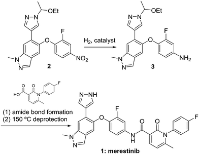
The hydrogenolysis of nitrobenzenes represents one of the most common synthetic approaches to the production of anilines, which are important feedstocks for materials, commodity, fine chemical, and pharmaceutical applications.1 While many non-catalytic methods for this reduction exist,2 catalytic hydrogenolysis represents an environmentally friendly approach due to the production of water as the sole stoichiometric by product, the ability to use low loadings of precious metal catalyst, and the ability to recover and/or recycle the catalyst. The reaction may be complicated by high heat of reaction3 and an impurity formation pathway that frequently leads to formation of genotoxic alerting structures.4 Merestinib (Scheme 1) is currently in phase 2 clinical testing for the treatment of solid tumors, and can be manufactured by the route shown.5 Key to the success of this approach is the hydrogenolysis of nitrobenzene 2 to aniline 3. Herein we describe our efforts that have resulted in an automated repeating batch with catalyst recycle approach to this transformation.For catalytic hydrogenolysis reactions, continuous processing has received significant attention due to processing benefits such as the ability to achieve high catalyst to substrate ratio, high surface area to volume ratio with high heat removal, ease and safety of achieving very high pressures, rapid vapour–liquid mass transfer, and safety benefits associated with smaller flow reactors relative to traditional batch pressure vessels. Common approaches to implementation in continuous flow mode include flowing substrate concurrently with hydrogen through packed columns of large particle size catalyst or sequestration of powdered catalyst in a traditional pressure vessel with continuous flow through the vessel. Packed bed reactors are a common choice for continuous flow reactions with heterogeneous catalysts, as was demonstrated in the streamlined continuous flow preparation of the anti-inflammatory drug (R)-rolipram.6 Packed bed hydrogenolysis can be accomplished at kg scale in the laboratory: for example full hydrogenolysis of ethyl nicotinate at 2.0 kg per day throughput7 or a tandem debenzylation and N–O bond cleavage at 0.5 kg per hour.8 Selectivity advantages can be realized compared to batch processes,8,9 and enantioselectivity is possible.10 Extremely high vapour–liquid mass transfer coefficients can be achieved, on the order of kLa 5–15 s−1.11 Furthermore, trickle-bed reactors are scalable from laboratory to industrial scale, and a scale factor as high as 3 × 10⁶ has been used.12 The packed column approach suffers from reduced catalyst activity and limited commercial availability of the larger particle size catalyst, which are normally used to avoid large pressure drops across the columns, as well as from the eventual need to exchange or repack the column upon loss of activity. As an alternative to a packed bed reactor, Pfizer researchers used a continuous stirred tank reactor system with sequestered catalyst for reduction of a dinitro intermediate.13 While use of powdered catalyst is allowed with the sequestered catalyst approach, catalyst distribution and mass transfer suffers, and upon exhaustion of the catalyst, it must be refreshed manually. We are using the automated repeating batch reactor with sequestered catalyst as an alternative to a truly continuous hydrogenation reactor. It allows high throughput with a 1 L stirred autoclave in a lab hood, and it integrates well with an otherwise fully continuous process. Within the context of merestinib, we set out to modify the sequestration approach in order to streamline the catalyst turnover and optimize the process to afford aniline 3.
Results and discussion
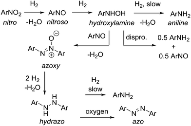
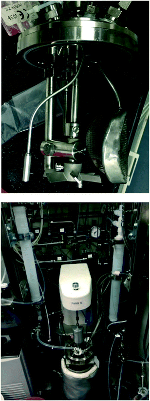
Reduction of aromatic nitro compounds is complicated by several reactive intermediates that exist during the process as shown in Scheme 2.14 Initial reduction of nitro compound to nitroso and then hydroxylamine is rapid, but reduction of the hydroxylamine to aniline is often slower, which allows for build up of the hydroxylamine, which can present a safety hazard. Hydroxylamine is reactive and N–N bond formation via condensation with a molecule of nitroso intermediate affords the azoxy dimer. The azoxy dimer can be hydrogenated to the hydrazo dimer, which is slow to reduce to aniline, and in our hands the hydrazo dimer is easily oxidized upon exposure to atmospheric oxygen to the azo dimer, which is not normally observed in the hydrogenation. This cascade was problematic from a reaction analysis perspective, as solutions containing hydroxylamine intermediate were prone to oxidation and formation of the nitroso intermediate and azoxy dimer, both of which are not believed to be present in the reaction mixture to a significant extent, but were observed as an artefact during HPLC analysis. For simplicity, the HPLC area% s of hydroxylamine, nitroso, and azoxy species were summed to yield a measure of total intermediate species present at a given reaction time (see ESI†).As an alternative to development of a fully continuous process, we set out with the concept of a system that could accomplish rapidly repeating batch reactions using a sequestered catalyst in a readily available autoclave reactor. The new technology could potentially enable continuous-like hydrogenation with powdered Pd/C catalyst, which is not normally used in a packed bed reactor because of pressure drop through the reactor. This is an advantage because it allows for the use of the same powdered catalyst identified in batch reaction screening to be used for scale up in small laboratory-based equipment instead of having to either switch to large specialized batch hydrogenation equipment, or adapt the process to a larger particle size catalyst suitable for packed bed application in flow. Operational safety would improve compared to typical batch processing because the reactor is small: 1 L is typically the maximum size hydrogenation autoclave used in a standard walk-in laboratory fume hood because 1 L of hydrogen at 68 bars is only about 3 moles, which is ∼30% of the LEL in a 6 m3 hood. A reactor system was assembled from standard small scale batch hydrogenation equipment. In Fig. 1, picture A depicts the autoclave head removed from the vessel, showing custom made filter frit, impeller, sampling frit, and outlet dip tube. The sampling frit is a much smaller surface area stainless steel mesh filter frit used to manually take samples from the reactor in the middle of a reaction cycle. The outlet dip tube does not have a filter frit, because it is used when the reactor empties slurry including spent catalyst. Behind the 1 L reactor in picture B is the automated cart with 1 L inlet and outlet transfer zones, automated valves, pressure transmitters and regulators.
Fig. 2 shows a design sketch of the automated repeating batch stirred tank hydrogenation reactor. Baseline conditions for the reactor included heating to 60 °C using the bath and pressurization with 60 psig hydrogen during reaction. These parameters were deliberately adjusted for the purposes of range finding during some of the reactor turnovers. The first feed was catalyst slurry and the second was nitrobenzene reagent solution. The catalyst slurry was charged once every 31–51 reactor volume turnovers because it was kept sequestered in the reactor until the catalyst activity dropped below a desirable level. Fresh nitrobenzene derivative reagent solution was automatically pumped into a 1 L transfer zone and then pushed into the reactor with 60 psig hydrogen each reaction cycle. The feed solution was heated in flow using coiled tube heat exchangers, so that it entered the reactor at 35 °C. This feed temperature was chosen so that heat of reaction would bring the internal temperature to 60 °C without overshoot. In this manner, reaction solution reached 60 °C within 4 minutes of starting the feed addition (see ESI†). The reactor had two intermittent feeds and two different exit ports. The first exit port was through a custom designed internal filter and through the valve labelled F in Fig. 2. When reaction product solution exited through this port, the catalyst remained in the reactor. The second exit port was through an open tube and through the valve labelled H in Fig. 2. When this exit port was activated, the entire contents of the reactor including the catalyst exited. In the 1 L exit transfer zone, the headspace hydrogen gas was automatically vented and purged multiple times with nitrogen before pushing the product to a filter or collection tank. The automated sequence is described in detail in the ESI.†
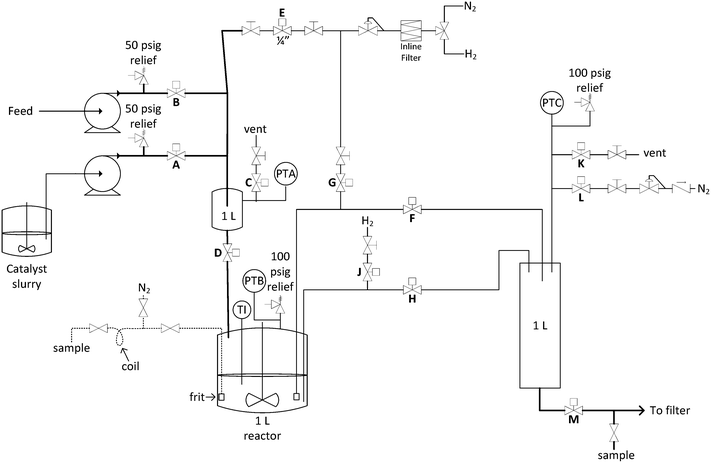 | ||
| Fig. 2 Process and instrumentation diagram for the automated repeating batch stirred-tank hydrogenation reactor. | ||
We were pleased with the initial hydrogenolysis results from the system when a THF solution of 2 was used in the reactor with a 26.8 mol% loading of a readily available source of water-wet 5% Pd/C powdered catalyst. It was demonstrated that the reaction was rapid given the high relative catalyst loading, and that the operational mechanism for catalyst sequestration and recycle was successful. A demonstration run was then conducted to enable further examination of reaction parameters in real time as well as to process 2.1 kg of substrate using this approach.
A key process impurity was the defluorinated aniline, which was difficult to reject downstream, therefore its formation needed to be minimized. During the experiment, the third fresh catalyst charge was closely monitored by HPLC to observe the defluorination levels over time. The first 4 turnovers used 0.1 equivalents of Et3N additive to minimize the impurity by reducing the activity of the fresh catalyst. Product HPLC area% gradually improved during the first 7 reactor volume turnovers and then remained ∼99.5%. The defluorinated impurity increased to about 0.06 HPLC area% for the 3rd and 4th reactor turnovers, then dropped to non-detect for the remainder of the production. Additional process impurities included the hydroxylamine, low levels of free pyrazole derived from deprotection of the ethoxyethyl group, the N-ethylaniline, derived from reductive amination of 3 with acetaldehyde from the protecting group fragmentation, and low levels of unidentified compounds (see ESI† for more detail).
As the catalyst aged, increased levels of hydroxylamine, nitroso, and azoxy compounds were observed in the HPLC analysis. It was interesting to note that while the rate of nitrobenzene consumption remained nearly constant, product formation slowed and the level of the intermediates greatly increased and persisted for a longer time (see ESI† for further details). This emphasizes that the initial reduction steps are rapid, while hydroxylamine reduction requires an active catalyst and is the most difficult step. As these intermediate species are all worrisome from a toxicity perspective, it is important to have sufficient assurance that they are either consumed in the hydrogenation, or sufficiently purged in downstream operations to requisite levels.
Samples of used catalyst were examined by ICP-MS for Pd content and this showed that there was only a slight decrease in Pd content as the catalyst aged. A sample of product solution was dried to a solid and was shown to contain only 10.7 ppm of Pd. This indicates that loss of catalyst activity is likely not primarily due to Pd leeching, and may be due to product-induced poisoning or physical changes on the catalyst surface. Additionally, the preparation of 2 involves a Pd-catalysed Suzuki cross coupling, which utilized a sulphur-based metal scavenging reagent shown to remain at ppm levels in 2, which could contribute to catalyst deactivation over time.
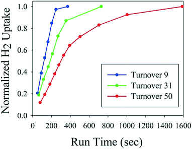
Fig. 3 shows hydrogen uptake as a function of catalyst age for the first of three fresh catalyst charges to the reactor. The automated reactor system monitored hydrogen uptake and decided when to push the reaction product out and start the next cycle. Thus, the system automatically compensated for longer reaction times to ensure full conversion of each cycle without any manual intervention. It is noteworthy that material throughput is not constant in this mode of operation, but should be consistent between catalyst recharges. If this type of reactor is used in the middle of an otherwise fully continuous process train, then surge vessels are required to maintain constant flows upstream and downstream. After 51 turnovers, the spent catalyst was removed from the reactor and recharged with fresh catalyst, as it was becoming less productive with the decreased catalyst activity (see ESI† for details).
Near the end of the catalyst life, higher pressure and temperature were investigated as a means to maintain a high reactor turnover rate, but neither factor significantly decreased reaction time (Fig. 4). With regard to pressure, after 37 reactor volume turnovers the reaction time had increased to about 17 minutes from the initial 4 minute time to reach full conversion. The reactor pressure set point was then changed between reactor turnovers. Although hydrogen uptake was slightly higher at the beginning of the reaction at 90 psig, the time to full conversion was still about 16–17 minutes and similar to the 40 and 60 psig trials. Therefore, reactor pressure had only marginal impact on rate in the range of 40–90 psig. Next, the temperature of the reactor was adjusted between reactor turnovers while using the same catalyst. Reactor turnover number 42 was run at 60 °C with reaction time of about 16 minutes to full conversion. The temperature was decreased to 40 °C for turnover 44 and the rate drastically dropped off, with the reaction requiring 35 minutes to reach full conversion. Finally, the temperature was increased to 65–70 °C for turnover 46; little difference in reaction rate was noted compared to the 60 °C experiment.
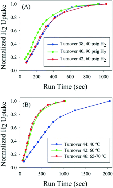 | ||
| Fig. 4 A: Hydrogen uptake as a function of pressure near the end of catalyst life. B: Hydrogen uptake as a function of temperature near the end of catalyst life. | ||
As an additional test, the potential of feeding a reagent slurry to the system was investigated. The poor solubility of 2 mandated the use of high solvent volumes: the baseline feed solution used 30 mL of THF per every gram of 2.15 To overcome this, 2 was fed as a slurry for the last six turnovers of the second catalyst charge using only 10 mL THF per gram of 2. These results were positive, revealing that the reaction performed well using the slurry feed and that reactor productivity increased using the more concentrated feed.16 Importantly, this capability represents a reduction in solvent use by 67% versus the homogeneous solution feed. To accomplish slurry transfer, 2 was stirred in a baffled vessel, and the suspension was intermittently pumped out of the vessel into the inlet transfer zone with a peristaltic pump. The process tubing was 3.2 mm inside diameter, which was sufficient to avoid fouling or clogging with solids for these six reactor turnovers (see ESI† for details). The process would need to be run for much longer duration to demonstrate robustness towards clogging, but in this short run there were no signs of fouling. Aniline product 3 was much more soluble in THF, so the product solution was homogeneous at room temperature. It is important to note that this mode of operation is not possible with a packed catalyst bed reactor, which requires the feed to be a homogeneous solution.
This campaign demonstrated high productivity using a customized 1 L stirred tank autoclave that was configured to accomplish automated catalyst and feed charging, pressurization with hydrogen, reaction, reaction endpoint determination, and reaction solution discharge prior to initiation of another reaction on the recycled catalyst. In total, the system achieved 107 reactor turnovers in 31 hours cumulative operating time. The reactor did not run unattended and was stopped overnight. 63 L of reaction solution was processed, yielding 1.9 kg of 3. Fresh catalyst was charged 3 times. Operating time for production of the first 0.9 kg was 16.3 hours, and operating time for production of the last 1 kg was 14.7 hours. Throughput and average product purity were higher for the last 1 kg of the campaign because the catalyst was changed out before activity significantly decreased. Overall material balance for the process was 95.7% because of THF solvent losses from the product tank which had a live nitrogen sweep, the assay yield of 3 was 94.5%, and the cumulative purity was >99 area% by HPLC.
The overall average catalyst loading for the first half of the campaign (51 reactor turnovers on 1 catalyst charge) was 0.53 mol%, and the overall average catalyst loading for the second half of the campaign (56 reactor turnovers and 2 catalyst charges) was 0.97 mol%. An overall catalyst loading of 0.77 mol% Pd was achieved, which is half the 1.5 mol% used in a similar batch process. For each individual cycle, the instantaneous catalyst loading was 26.8 mol% because catalyst was sequestered for a large number of turnovers. The high instantaneous catalyst loading enabled fast reaction rates and many automated reactor turnovers per day.
The entire product solution was combined and forward processed as a single batch. Although there was variability throughout each of the 3 catalyst life cycles, there was none in the combined batch. If processing is continued for multiple batches, as long as the catalyst life cycle is less than the batch collection time, there will not be batch to batch variability. This is an advantage of the repeating batch stirred tank compared to a packed bed scenario, in which the catalyst bed change-out time is longer duration than batch collection time. For example, if the packed catalyst bed runs for 1 week between change-outs, and if the batch collection time is 1 day, then it can be expected that batches will have different impurity profiles depending on whether they were generated early versus late in the catalyst life cycle. Additionally, no manual intervention is required to change the catalyst in the repeating batch case, whereas the potentially hazardous catalyst bed must removed from the reactor if it is to be repacked and reused.
Although this automated repeating batch process is not continuous, it has many of the practical advantages of continuous hydrogenation with heterogeneous catalyst:
1.The catalyst is sequestered in the reactor, the instantaneous catalyst loading is high, and the catalyst is reused many times.
2.There is a high volume turnover rate, for example 70 reactor volume turnovers per day.
3.The reactor is small compared to batch processing for the same daily throughput (about 35–70× smaller than batch).
4.Heat/cool time is minimized. There is fast heat up via flow through heat exchangers at the reactor inlet, and the reactor jacket remains constant at the desired temperature.
5.There is less material at risk at any one time in the reactor compared to batch.
6.Lower capital cost. Compare the cost of a 1 L autoclave and a lab hood to the cost of a 50 L autoclave and a hydrogenation bunker.
7.With the strategic use of surge vessels, this hydrogenation method could conceivably connect two otherwise fully continuous unit operations in order to form a linked chain of hybrid batch/flow unit operations in fume hoods for “end-to-end” type manufacturing.17
This methodology can also be compared to the standard batch hydrogenation process, in which fresh catalyst is added for each batch. For the nitro reduction process described in this manuscript, the batch reaction time is about 6 hours, and it is possible to achieve about 2 batches per day maximum because of the charging, purging, emptying, and filtering. The automated repeating batch reactor with sequestered catalyst achieved 107 reactor volume turnovers in 31 hours of total operation time, while the standard batch process would not be able to achieve 3 volume turnovers in the same time period. Therefore, the required reactor size could be reduced by more than 36× compared to standard batch, while achieving the same throughput, which is a significant safety advantage. Furthermore, at the productivity of 1.3 kg per day, this method enabled the production to take place in a standard laboratory fume hood rather than a hydrogenation bunker, as there was only about 0.05 moles hydrogen in the headspace of the reactor.
This methodology is especially valuable if rapid scale up is required, as for an early phase material delivery. If a batch hydrogenation performs acceptably, it is easier to transition into production mode with the automated repeating batch stirred tank than to develop a packed bed reaction. If batch experiments prove that reaction performance is acceptable with a high loading of powdered catalyst and the reaction time is on the order of 10 minutes, then the process is ready for >30 L per day production with an automated 1 L autoclave. In contrast, converting to a packed catalyst bed continuous reactor involves further investigation and characterization. A larger particle size catalyst must be identified, which is difficult to screen in batch mode because vapour/liquid mass transfer is drastically different in a trickle bed compared to a stirred tank. Many parameters such as catalyst wetting efficiency, the impact of adsorption/desorption on the transitions, the difference between substrate and solvent mean residence times, the procedure for pre-conditioning, pre-wetting, and pre-treating a new packed bed, the pressure drop across the packed catalyst bed, and the liquid fill fraction in the packed catalyst bed should be tested in flow. Determination of the flow regime should be tested in the continuous reactor (trickle, pulse, spray, or bubble), as well as the gas and liquid linear velocities at the transition points from one flow regime to another, as it may impact reactor performance. For these reasons, the automated repeating batch stirred tank requires less time and resource investment in order to scale up.
Conclusions
An automated repeating batch stirred tank reactor with sequestered catalyst was used for development and scale up of the hydrogenolysis of 2 to 3 using a standard Pd/C powdered catalyst. This effort demonstrated high productivity from a 1 L stirred tank autoclave. 63 L of reaction solution was processed, and 1.9 kg of aniline was produced over 31 hours cumulative operating time in 94.5% assay yield and >99% HPLC purity. The repeating batch process had many of the practical advantages of a continuous hydrogenation with heterogeneous catalyst. In the demonstration run, the overall catalyst loading was 0.77 mol% Pd, which was superior to a similar batch process. Each individual reaction experienced a catalyst loading of 26.8 mol%, which allowed for rapid reactions and high throughput. The reaction rate decreased over time as the catalyst aged, and the control system monitored hydrogen uptake and automatically emptied and refilled the reactor when each reaction cycle was complete. The reactor provided an effective means for screening the impact of temperature and pressure on the reaction rate. Nitrobenzene 2 could be fed as a slurry to the repeating batch reactor in order to demonstrate a drastic reduction of solvent usage; an advantage compared to packed bed reactors, which require homogeneous solution feeds. Lastly, it is envisioned that this technology will prove easier to scale up compared to packed bed reactor systems.Acknowledgements
The authors gratefully acknowledge Mr. Bradley Campbell for analytical assistance and Mr. Richard Spears of D&M continuous solutions for designing the filter frit and constructing and operating the automated repeating batch stirred tank reactor system. We thank Dr. Bret Huff for initiating and driving the continuous processing initiatives at Eli Lilly.Notes and references
- The chemistry of Anilines, Part 1, ed. Z. Rappoport, John Wiley & Sons Ltd., West Sussex, 2007 Search PubMed.
- G. W. Kabalka and R. S. Varma, Reduction of Nitro and Nitroso Compound, In Comprehensive Organic Synthesis, ed. B. M. Trost and I. Flemming, Pergamon Press, Oxford, 1st edn, 1991, vol. 8, p. 363 Search PubMed.
- J.-L. Gustin, Org. Process Res. Dev., 1998, 2, 27 CrossRef CAS.
- R. Angelaud, M. Reynolds, C. Venkatramani, S. Savage, H. Trafelet, T. Landmesser, P. Demel, M. Levis, O. Ruha, B. Rueckert and H. Jaeggi, Org. Process Res. Dev., 2016, 20, 1509 CrossRef CAS.
- T. Li, M. A. Pobanz, C. Shih, Z. Wu, W. J. Yang and B. Zhong, Preparation of amidophenoxyindazoles as inhibitors of c-MET, US8030302 B220111004 and WO2010011538 A120100128, 2010 CrossRef CAS PubMed; S. B. Yan, V. L. Peek, R. Ajamie, S. G. Buchanan, J. R. Graff, S. A. Heidler, Y. Hui, K. L. Huss, B. W. Konicek, J. R. Manro, C. Shih, J. A. Stewart, T. R. Stewart, S. L. Stout, M. T. Uhlik, S. L. Um, Y. Wang, W. Wu, L. Yan, W. J. Yang, B. Zhong and R. A. Walgren, Invest. New Drugs, 2013, 31, 833 CrossRef CAS PubMed; M. O. Frederick, J. R. Calvin, R. F. Cope, M. E. LeTourneau, K. T. Lorenz, M. D. Johnson, T. D. Maloney, Y. J. Pu, R. D. Miller and L. E. Cziesla, Org. Process Res. Dev., 2015, 19, 1411 CrossRef; N. J. Kallman, C. Liu, M. H. Yates, R. J. Linder, J. C. Ruble, E. F. Kogut, L. E. Patterson, D. L. T. Laird and M. M. Hansen, Org. Process Res. Dev., 2014, 18, 501 CrossRef.
- J. M. Hawkins, Nature, 2015, 520, 302 CrossRef CAS PubMed.
- T. Ouchi, C. Battilocchio, J. M. Hawkins and S. V. Ley, Org. Process Res. Dev., 2014, 18, 1560 CrossRef CAS.
- N. Zaborenko, R. J. Linder, T. M. Braden, B. M. Campbell, M. M. Hansen and M. D. Johnson, Org. Process Res. Dev., 2015, 19, 1231 CrossRef CAS.
- C. V. Rode, P. R. Tayade, J. M. Nadgeri, R. Jaganathan and R. V. Chaudhari, Org. Process Res. Dev., 2006, 10, 278 CrossRef CAS.
- N. Kunzle, J. W. Soler and A. Baiker, Catal. Today, 2003, 79–80, 503 CrossRef CAS.
- M. W. Losey, M. A. Schmidt and K. F. Jensen, Ind. Eng. Chem. Res., 2001, 12, 2555 CrossRef.
- D. A. Hickman, M. T. Holbrook, S. Mistretta and S. J. Rozeveld, Ind. Eng. Chem. Res., 2013, 44, 15287 CrossRef.
- J. G. Van Alsten, L. M. Reeder, C. L. Stanchina and D. J. Knoechel, Org. Process Res. Dev., 2008, 12, 989 CrossRef CAS.
- F. Haber, Z. Elektrochem. Angew. Phys. Chem., 1898, 4, 506 CrossRef CAS.
- Solubility of 2 in pure THF was measured at 33.4 mg mL−1 at 22 °C, therefore 1 kg of 2 would require a minimum of 29.9 L of THF to form a solution.
- 590 mL of solution (∼20 of 2) required ∼570 seconds to complete (28.5 s per gram) whereas 16 mL of slurry (∼60 g of 2) required 1200 seconds (20.0 s per gram).
- S. Mascia, P. L. Heider, H. Zhang, R. Lakerveld, B. Benyahia, P. I. Barton, R. D. Braatz, C. L. Cooney, J. M. B. Evans, T. F. Jamison, K. F. Jensen, A. S. Myerson and B. L. Trout, Angew. Chem., Int. Ed., 2013, 52, 12359 CrossRef CAS PubMed.
Footnote |
| † Electronic supplementary information (ESI) available: Experimental details, detailed description of equipment set and operational parameters, additional reaction screening details and data. See DOI: 10.1039/c7re00002b |
| This journal is © The Royal Society of Chemistry 2017 |

