Hybrid energy storage of battery-type nickel hydroxide and supercapacitor-type graphene: redox additive and charge storage mechanism†
Pichamon
Sirisinudomkit
ab,
Pawin
Iamprasertkun
ab,
Atiweena
Krittayavathananon
a,
Tanut
Pettong
ab,
Peerapan
Dittanet
b,
Pinit
Kidkhunthod
c and
Montree
Sawangphruk
 *a
*a
aDepartment of Chemical and Biomolecular Engineering, School of Energy Science and Engineering, Vidyasirimedhi Institute of Science and Technology, Rayong 21210, Thailand. E-mail: montree.s@vistec.ac.th
bDepartment of Chemical Engineering, Centre for Advanced Studies in Nanotechnology and Its Applications in Chemical Food and Agricultural Industries, NANOTEC-KU-Centre of Excellence on Nanoscale Materials Design for Green Nanotechnology, Kasetsart University, Bangkok 10900, Thailand
cSynchrotron Light Research Institute (Public Organization), 111 University Avenue, Muang District, Nakhon Ratchasima 30000, Thailand
First published on 23rd February 2017
Abstract
Herein, hybrid energy storages (HESs) of battery-type Ni(OH)2 and supercapacitor-type electrochemically reduced graphene oxide (ERGO) were fabricated using potassium ferricyanide (K3Fe(CN)6) as a redox additive in KOH electrolyte for high specific energy and power applications. The as-fabricated HES of Ni(OH)2//ERGO in a single coin cell (CR2016) size in 4 mM K3[Fe(CN)]6 in 1 M KOH provides a wide working voltage up to 1.6 V and exhibits a maximum specific energy of 85 W h kg−1 at the specific power of 726 W kg−1 with a high capacity retention over 88% after 10![[thin space (1/6-em)]](https://www.rsc.org/images/entities/char_2009.gif) 000 cycles, while the HES in 1 M KOH provides a lower maximum specific energy of 61 W h kg−1. A Fe(CN)63−/Fe(CN)64− redox couple has a great electrochemical reversibility in nature since Fe(CN)63− can obtain electrons from Ni(OH)2 through the reduction process and Fe(CN)64− can donate electrons to NiOOH for the oxidation process. The HES reported herein may be practically used for high energy applications.
000 cycles, while the HES in 1 M KOH provides a lower maximum specific energy of 61 W h kg−1. A Fe(CN)63−/Fe(CN)64− redox couple has a great electrochemical reversibility in nature since Fe(CN)63− can obtain electrons from Ni(OH)2 through the reduction process and Fe(CN)64− can donate electrons to NiOOH for the oxidation process. The HES reported herein may be practically used for high energy applications.
Introduction
Hybrid energy storages (HESs), which consist of a battery-type active material on a positive electrode and a supercapacitor-type material on a negative electrode, are of significant interest since they can provide a wide working potential and high specific energy and power.1–3 In this study, a battery-type material, nickel hydroxide (Ni(OH)2), was used as the positive electrode because of its high theoretical specific capacity,4 high redox reversibility, low-cost, abundant natural resources, and excellent environmental compatibility.5,6 On the other hand, a supercapacitor-type material, electrochemically reduced graphene oxide (ERGO), was employed as the negative electrode due to its high specific power and fast charge/discharge rate.In general, Ni(OH)2 has two types of polymorphs: α-Ni(OH)2 and β-Ni(OH)2. α-Ni(OH)2 is known as hydrated nickel hydroxide with more disordered structure and larger interlayer separation (almost 8.0 Å) than β-Ni(OH)2 (around 4.6 Å) due to the intercalated anions and water molecules bonded to the hydroxyl groups by hydrogen bonds.7,8 Therefore, α-Ni(OH)2 exhibits superior performance. It can be electrochemically converted to γ-NiOOH without any mechanical deformation unlike β-Ni(OH)2, which has to transform to β-NiOOH before changing to γ-NiOOH, leading to a specific capacitance decay.9,10 For this reason, in this study, α-Ni(OH)2 was synthesized through an electrodeposition approach, which is simple, economic, fast, eco-friendly, and provides accurate control of the surface microstructure and phase of the deposited films without using any binders. Moreover, direct electrodeposition is also found to make strong attachment between current collector and electroactive material when compared with other coating methods. The capacitance loss of the device is small owing to the small internal resistance.11
To enhance the electronic conductivity and increase the operating voltage, graphene was then used as a negative electrode owing to its high thermal and electrical conductivity, excellent chemical stability, large theoretical specific surface area, and high theoretical specific capacitance (550 F g−1).12 Although there are numerous routes to synthesize graphene, the favorable method is the synthesis of graphene materials via graphene oxide (GO) precursor owing to cheap, scalable, versatile, and easy processing.13 Despite various methods for the reduction of GO, electrochemical reduction, which is a facile and environmentally friendly method and can deoxygenate oxygen-containing functional groups from GO, is a captivated route. This is because other methods, such as chemical reduction of GO, require toxic reducing agents i.e., hydrazine, dimethyl hydrazine, metal hydrides, and hydroquinone, which can also contaminate the resulting products and even be harmful to human health and the environment.13
To further improve the charge capacity of energy storage, adding small quantities of redox additives, such as potassium ferricyanide (K3[Fe(CN)]6), into the electrolytes was also investigated in this study.14 The as-fabricated HESs of Ni(OH)2//ERGO in a single coin cell (CR2016) size in 4 mM K3[Fe(CN)]6 in 1 M KOH can provide a wide working voltage up to 1.6 V, a maximum specific energy of 85 W h kg−1 at the specific power of 726 W kg−1 with a high capacity retention over 88% after 10![[thin space (1/6-em)]](https://www.rsc.org/images/entities/char_2009.gif) 000 cycles. In addition, the charge storage mechanism of the Ni(OH)2 electrode using 4 mM K3[Fe(CN)]6 in 1 M KOH electrolyte was investigated via in situ X-ray absorption spectroscopy.
000 cycles. In addition, the charge storage mechanism of the Ni(OH)2 electrode using 4 mM K3[Fe(CN)]6 in 1 M KOH electrolyte was investigated via in situ X-ray absorption spectroscopy.
Experimental
Preparation of graphene oxide-coated carbon fiber electrode
Carbon fiber paper (CFP, SGL CARBON SE, Germany) with 3.5 × 3.5 cm2 area was treated in a mixture of concentrated sulfuric acid (98%, QRec) and concentrated nitric acid (QRec) in the ratio of 3![[thin space (1/6-em)]](https://www.rsc.org/images/entities/char_2009.gif) :
:![[thin space (1/6-em)]](https://www.rsc.org/images/entities/char_2009.gif) 1 volume by volume at 60 °C for 1 h.15 This can turn the hydrophobic surface of CFP to hydrophilic CFP. Then, the treated CFP was rinsed several times with deionized water, dried at 60 °C for 24 h, and then cut in a rectangular shape of 1 × 1 cm2 area for a half-cell testing and a circle shape with the diameter of 1.58 cm for a full-cell device. GO produced by a modified Hummers method with our modification16–18 was then spray-coated on the treated CFP substrates.
1 volume by volume at 60 °C for 1 h.15 This can turn the hydrophobic surface of CFP to hydrophilic CFP. Then, the treated CFP was rinsed several times with deionized water, dried at 60 °C for 24 h, and then cut in a rectangular shape of 1 × 1 cm2 area for a half-cell testing and a circle shape with the diameter of 1.58 cm for a full-cell device. GO produced by a modified Hummers method with our modification16–18 was then spray-coated on the treated CFP substrates.
Electrochemical reduction of graphene oxide
The GO-coated CFP electrode was then subjected to electrochemical reduction using a standard three-electrode system through a chronoamperometry method at −1.2 V vs. Ag/AgCl in 0.5 M NaCl using a Metrohm AUTOLAB potentiostat (PGSTAT 302N made in the Netherlands running NOVA version 1.10.3 software). After the electrochemical reduction process, the as-synthesized ERGO on the CFP substrate was then washed 5 times by Milli-Q water and vacuum dried at 60 °C for 8 h.Electrodeposition of nickel hydroxide
Ni(OH)2 was electrodeposited on CFP by applying −0.9 V vs. Ag/AgCl (3 M KCl) through a chronoamperometry method using a Metrohm AUTOLAB potentiostat (PGSTAT 302N made in the Netherlands running NOVA version 1.10.3 software) for 5 minutes. A 0.1 M nickel(II) nitrate hexahydrate (Ni(NO3)2·6H2O, 97% QRec) solution in 0.5 M sodium nitrate (NaNO3, 99.5% QRec) solution was used as a precursor. The platinum wire and Ag/AgCl were used as the counter and the reference electrodes, respectively. After the electrodeposition process, the as-synthesized Ni(OH)2 on the substrate was then washed 5 times with deionized water and vacuum dried at 50 °C for 8 h.Morphological and structural characterizations
The morphology of the as-synthesized materials was characterized by field-emission scanning electron microscopy (FE-SEM, JSM-7001F (JEOL Ltd., Japan)) and transmission electron microscopy (TEM, JEM 1220 (JEOL Ltd., Japan)). The functional groups were analyzed by Fourier transform infrared spectroscopy (FTIR, PerkinElmer Paragon 1000) and X-ray diffraction (XRD, Bruker optics, Germany).Fabrication of HES and the electrochemical evaluation
The HES were assembled from the negative and positive electrodes with a geometrical coin cell (CR2016). Note that the finely tuned and balanced masses of Ni(OH)2 and ERGO active materials were 0.76 and 2.24 mg, respectively. Hydrolyzed polyethylene (PE) film with a thickness of 25 μm used as the separator was soaked in 4 mM K3[Fe(CN)]6 in 1 M KOH for 10 min before being used. Then, the separator was inserted between the positive and negative electrodes. The coin cell was then assembled by pressing with a crimper machine at 100 psi. The electrochemical property of the as-fabricated energy storages was evaluated by cyclic voltammetry (CV), galvanostatic charge–discharge (GCD), and electrochemical impedance spectroscopy (EIS) using a Metrohm AUTOLAB potentiostat (PGSTAT 302N made in the Netherlands running NOVA software version 1.11).Charge storage mechanism characterization
For the in situ electrochemical X-ray absorption spectroscopy (XAS) measurement, a chronoamperometry method was used at different potentials to evaluate the electrochemical property of the electrode. In this measurement, a 3-electrode system using Ag/AgCl as the reference electrode, Pt wire as the counter electrode, and the as-prepared Ni(OH)2 as the working electrode was carried out in 1 M KOH with 4 mM K3[Fe(CN)]6 concentration. More details of XAS measurement can be found in our previous report elsewhere.1Results and discussion
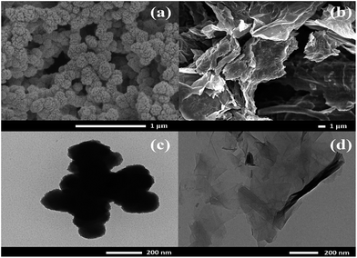
The morphology of the as-synthesized materials was characterized by FE-SEM and TEM techniques. The nanoparticles of Ni(OH)2 were uniformly deposited on the carbon fiber paper (CFP) that was used as a substrate, for which, the particles were agglomerated, forming a large framework (Fig. 1a). Fig. 1b displays graphene oxide sheets electrochemically reduced at −1.2 V vs. Ag/AgCl in 0.5 M NaCl. A TEM image of Ni(OH)2 shows the dark spots with 100 nm diameter agglomerated Ni(OH)2 particles (Fig. 1c). A few layers of ERGO sheets overlapped each other, as shown in Fig. 1d.To further investigate the structure of the as-synthesized materials, FTIR of Ni(OH)2 coated on CFP presents a broad peak at 3448 cm−1 due to hydroxyl functional groups (O–H). The bending vibration of water molecules is shown as a broad peak at 1632 cm−1 and the sharp peak at 1383 cm−1 is assigned to be characteristic of the interlayered NO3−. An Ni–O–H vibrational mode is presented at 648 cm−1 and a Ni–O stretching vibrational mode is displayed at 467 cm−1 (Fig. 2a).19 The XRD patterns exhibit characteristic rhombohedral α-Ni(OH)2 with lattice parameters of a = b = 3.08 Å and c = 23.41 Å (JCPDS 38-715)20 and γ-NiOOH (JCPDS 06-075). The interlayer separation determined from the Bragg' formula (nλ = 2d![[thin space (1/6-em)]](https://www.rsc.org/images/entities/char_2009.gif) sin
sin![[thin space (1/6-em)]](https://www.rsc.org/images/entities/char_2009.gif) θ) is 7.0 Å (Fig. 2b).21 Note that the XPS results of Ni(OH)2/CFP can be found in the ESI.†
θ) is 7.0 Å (Fig. 2b).21 Note that the XPS results of Ni(OH)2/CFP can be found in the ESI.†
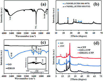 | ||
| Fig. 2 (a) FTIR spectrum and (b) XRD pattern of the as-electrodeposited Ni(OH)2 as well as (c) FTIR spectra and (d) XRD patterns of GO and ERGO coated on carbon fiber paper (CFP). | ||
In Fig. 2c, the FTIR spectrum of GO displays the stretching vibrational modes of oxygen-containing groups, for which, a major absorption band at 3340 cm−1 is assigned to the O–H group and that at 1460 cm−1 is due to the C–OH group. The absorption peak at 1730 cm−1 can be assigned to C![[double bond, length as m-dash]](https://www.rsc.org/images/entities/char_e001.gif) O stretching mode of the carboxylic groups and a peak at 1630 cm−1 corresponds to the C
O stretching mode of the carboxylic groups and a peak at 1630 cm−1 corresponds to the C![[double bond, length as m-dash]](https://www.rsc.org/images/entities/char_e001.gif) C skeletal vibration of the unoxidized graphitic domain. The two absorption peaks at ca. 1226 cm−1 and 1044 cm−1 are assigned to the C–O stretching vibrational modes. After applying the negative potential (−1.2 V vs. Ag/AgCl) for 10 min, GO-coated CFP was reduced to ERGO. The result, as shown in Fig. 2c, represents the fingerprint of graphene, which can confirm the successful electrochemical reduction process.13
C skeletal vibration of the unoxidized graphitic domain. The two absorption peaks at ca. 1226 cm−1 and 1044 cm−1 are assigned to the C–O stretching vibrational modes. After applying the negative potential (−1.2 V vs. Ag/AgCl) for 10 min, GO-coated CFP was reduced to ERGO. The result, as shown in Fig. 2c, represents the fingerprint of graphene, which can confirm the successful electrochemical reduction process.13
To further confirm the FTIR result, XRD patterns of GO/CFP, ERGO/CFP, and bare CFP are displayed in Fig. 2d. XRD patterns of both GO/CFP and ERGO/CFP consist of the major characteristics of CFP. However, the XRD pattern of GO/CFP also presents a peak at 10.5° corresponding to the diffraction of the (002) planes of GO. Upon electrochemical reduction of GO/CFP, the characteristic diffraction peak (002) of GO disappeared and exhibited the characteristics of rGO instead.22
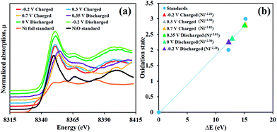
The charge storage mechanism of the as-prepared α-Ni(OH)2 electrode was investigated through the in situ XAS technique together with the chronoamperometry in 4 mM K3[Fe(CN)]6 in 1 M KOH electrolyte by applying the potentials from −0.2, 0.3 to 0.7 V vs. Ag/AgCl and turning back from 0.7, 0.35, 0 to −0.2 V vs. Ag/AgCl. The Ni K-edge XANES of the samples were calculated and compared with those of Ni foil (Ni0, 8333.00 eV), NiO (Ni2+, 8345.20 eV) and LaNiO3 (Ni3+, 8348.20 eV) standards.23
As shown in Fig. 3a and b, the Ni(OH)2 electrode, initially charged at −0.2 V vs. Ag/AgCl, has the Ni K-edge fluorescence energy of 8345.25 eV (Ni2.26+) before being increased to 8345.85 eV (Ni2.38+) at 0.3 V vs. Ag/AgCl and 8348.15 eV (Ni2.82+) at 0.7 V vs. Ag/AgCl. This is because an oxidation reaction of Ni(OH)2 with OH− generates NiOOH. For the discharging process, the Ni K-edge fluorescence energy was 8348.07 eV (Ni2.81+), for which, the fully charged Ni(OH)2 electrode was first discharged at 0.35 V vs. Ag/AgCl (Ni2.81+) before being reduced to 8345.38 eV (Ni2.38+) at 0 V vs. Ag/AgCl and 8345.25 eV (Ni2.26+) at −0.2 V vs. Ag/AgCl.
Not only can these two steps of increasing and decreasing oxidation number of Ni confirm that the Ni(OH)2 electrode has highly reversible redox reaction behaviour when 4 mM K3[Fe(CN)]6 is used as a redox additive but also they can present the reaction mechanisms as follows;
| α-Ni(OH)2 + OH− ↔ γ-NiOOH + H2O + e− | (1) |
| α-Ni(OH)2 + Fe(CN)63− ↔ γ-NiOOH + Fe(CN)64− | (2) |
A Fe(CN)63−/Fe(CN)64− redox couple has a great electrochemical reversibility in nature since Fe(CN)63− can obtain electrons from Ni(OH)2 through the reduction process and Fe(CN)64− can donate electrons to NiOOH for the oxidation process.24–26
For the electrochemical evaluation, optimization of the mass ratio between positive and negative electrodes through CV curves in a three-electrode system at 25 mV s−1 was first carried out. The optimized mass ratio between Ni(OH)2 and ERGO was equal to 0.34 (See Fig. S2 in the ESI†).
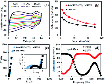
As observed from Fig. 4a, the CV curves show that Ni(OH)2//ERGO HES using 4 mM K3[Fe(CN)]6 as the redox additive can provide a wide working voltage from 0.0 to 1.6 V, which is wider than that of the Ni(OH)2 symmetric energy storage.27 This is due to the combination of operating window potential range of Ni(OH)2 and ERGO materials. Furthermore, this pair of current peaks has a trend to increase with the scan rate and the position of anodic peaks slightly shifts along with the increasing scan rate.28,29
Fig. 4b presents the performance of a full-cell device according to the CV technique. The results are 379, 329, 268, 216, 174, and 157 mA h g−1 (273, 225, 175, 140, 113, and 101 F g−1) at 5, 10, 25, 50, 75, and 100 mV s−1, respectively.
To study the resistance of the cell, the EIS of the as-fabricated energy storages was performed in 1 M KOH by applying a sinusoidal signal of 10 mV in the range of frequencies from 1 mHz to 100 kHz (Fig. 4c). The charge transfer resistance (Rct) of Ni(OH)2//ERGO HES in 4 mM K3[Fe(CN)]6 in 1 M KOH is 5.7 Ω, representing a value close to that of Ni(OH)2//ERGO HES using only 1 M KOH (5 Ω). This indicates that adding a redox additive does not inhibit the charge transfer kinetics of the HES. In addition, the relaxation time (τ0), which is the minimum time required for discharging the stored energy in the as-fabricated HES, was calculated, for which, it was observed that the smaller the relaxation time, the higher the power of the HES.30–32 Hence, the response of frequency (f0), corresponding to the maximum point of the energy curve, was estimated and represented at 0.193 Hz. Thus, the relaxation time constant, which is equal to 1/(2πf0), can exhibit a small value of 0.824 s (Fig. 4d). Consequently, the as-fabricated HES can provide quick access to the discharging process and is also substantially faster than the as-fabricated device in 1 M KOH (1.75 s) and those reported in other previous studies.31
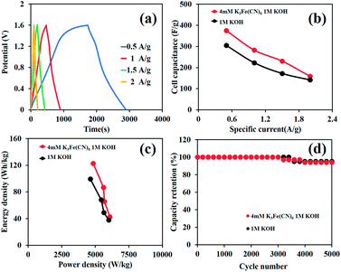
In addition, GCD curves of the as-fabricated HES are shown in Fig. 5a and the calculated cell capacities from the GCD method are 420, 330, 220, 160, and 120 mA h g−1 (283, 231, 158, 115, and 87 F g−1) at 1, 1.5, 2, 2.5, and 3 A g−1, respectively (Fig. 5b). Note that Table S1 of the ESI† shows the comparison of the charge storage performance of Ni hydroxide/oxide-based supercapacitors. Remarkably, the device can display high specific energies of 85, 59, 38, 28, and 23 W h kg−1 at the power densities of 726, 969, 1241, 1552, and 2092 W kg−1, respectively (Fig. 5c), which are much higher than those of the as-fabricated devices in pure 1 M KOH (61, 38, 31, 22, and 13 W h kg−1 at the power densities of 673, 848, 1157, 1374, and 1706 W kg−1, respectively). The capacity retention of the as-fabricated device is also shown in Fig. 5d. The HES devices in both 1 MKOH and 4 mM K3[Fe(CN)]6 in 1 M KOH can achieve over 94% capacity retention over 5000 charge/discharge cycles and still retain 88% capacity retention after 10![[thin space (1/6-em)]](https://www.rsc.org/images/entities/char_2009.gif) 000 cycles.
000 cycles.
Conclusions
GO was coated on CFP by a spray-coating process and then electrochemically reduced to ERGO/CFP, which was then used as the supercapacitor-type electrode material. Simultaneously, α-Ni(OH)2 was electrodeposited on the ERGO/CFP and used as the battery-type electrode material. The HES of these electrode materials in 4 mM potassium ferricyanide (K3Fe(CN)6) in 1 M KOH electrolyte was subsequently fabricated and electrochemically tested. The as-fabricated HES of Ni(OH)2//ERGO in a single coin cell (CR2016) size using a redox additive provides a wide working voltage up to 1.6 V and a maximum specific energy of 85 W h kg−1 at the specific power of 726 W kg−1 with the high capacity retention over 88% after 10![[thin space (1/6-em)]](https://www.rsc.org/images/entities/char_2009.gif) 000 cycles. However, the HES in 1 M KOH provides a lower maximum specific energy of 61 W h kg−1. A Fe(CN)63−/Fe(CN)64− redox couple has a great electrochemical reversibility in nature since Fe(CN)63− can obtain electrons from Ni(OH)2 through the reduction process and Fe(CN)64− can donate electrons to NiOOH for the oxidation process. The HES reported herein may be practically used for high energy applications.
000 cycles. However, the HES in 1 M KOH provides a lower maximum specific energy of 61 W h kg−1. A Fe(CN)63−/Fe(CN)64− redox couple has a great electrochemical reversibility in nature since Fe(CN)63− can obtain electrons from Ni(OH)2 through the reduction process and Fe(CN)64− can donate electrons to NiOOH for the oxidation process. The HES reported herein may be practically used for high energy applications.
Acknowledgements
This work was financially supported by the Thailand Research Fund and Vidyasirimedhi Institute of Science and Technology (RSA5880043). P. Sirisinudomkit appreciates the financial support (M. Eng. Scholarship) received from the Faculty of Engineering and the National Research University Project of Thailand (NRU) at Kasetsart University. Synchrotron Light Research Institute (BL5.2) (Public Organization), Thailand for XANES facility, and the Frontier Research Centre at VISTEC are also acknowledged.References
- P. Iamprasertkun, A. Krittayavathananon, A. Seubsai, N. Chanlek, P. Kidkhunthod, W. Sangthong, S. Maensiri, R. Yimnirun, S. Nilmoung, P. Pannopard, S. Ittisanronnachai, K. Kongpatpanich, J. Limtrakul and M. Sawangphruk, Sci. Rep., 2016, 6, 37560 CrossRef CAS PubMed.
- J. Yan, Z. Fan, W. Sun, G. Ning, T. Wei, Q. Zhang, R. Zhang, L. Zhi and F. Wei, Adv. Funct. Mater., 2012, 22, 2632–2641 CrossRef CAS.
- J. Ji, L. L. Zhang, H. Ji, Y. Li, X. Zhao, X. Bai, X. Fan, F. Zhang and R. S. Ruoff, ACS Nano, 2013, 7, 6237–6243 CrossRef CAS PubMed.
- H. Wang, H. S. Casalongue, Y. Liang and H. Dai, J. Am. Chem. Soc., 2010, 132, 7472–7477 CrossRef CAS PubMed.
- X. H. Xia, J. P. Tu, Y. Q. Zhang, Y. J. Mai, X. L. Wang, C. D. Gu and X. B. Zhao, J. Phys. Chem. C, 2011, 115, 22662–22668 CAS.
- W. Jiang, D. Yu, Q. Zhang, K. Goh, L. Wei, Y. Yong, R. Jiang, J. Wei and Y. Chen, Adv. Funct. Mater., 2015, 25, 1063–1073 CrossRef CAS.
- M. Salavati-Niasari, H. Seyghalkar, O. Amiri and F. Davar, J. Cluster Sci., 2013, 24, 365–376 CrossRef CAS.
- X. Meng and D. Deng, J. Mater. Chem. A, 2016, 4, 6919–6925 CAS.
- G. Hu, C. Li and H. Gong, J. Power Sources, 2010, 195, 6977–6981 CrossRef CAS.
- P. V. Kamath, M. Dixit, L. Indira, A. K. Shukla, V. G. Kumar and N. Munichandraiah, J. Electrochem. Soc., 1994, 141, 2956–2959 CrossRef CAS.
- J. Yan, Q. Wang, T. Wei and Z. Fan, Adv. Energy Mater., 2014, 4, 1300816 CrossRef.
- H. J. Choi, S. M. Jung, J. M. Seo, D. W. Chang, L. Dai and J.-B. Baek, Nano Energy, 2012, 1, 534–551 CrossRef CAS.
- S. Y. Toh, K. S. Loh, S. K. Kamarudin and W. R. W. Daud, Chem. Eng., 2014, 251, 422–434 CrossRef CAS.
- L. Chen, Y. Chen, J. Wu, J. Wang, H. Bai and L. Li, J. Mater. Chem. A, 2014, 2, 10526–10531 CAS.
- P. Suktha, P. Chiochan, P. Iamprasertkun, J. Wutthiprom, N. Phattharasupakun, M. Suksomboon, T. Kaewsongpol, P. Sirisinudomkit, T. Pettong and M. Sawangphruk, Electrochim. Acta, 2015, 176, 504–513 CrossRef CAS.
- P. Iamprasertkun, A. Krittayavathananon and M. Sawangphruk, Carbon, 2016, 102, 455–461 CrossRef CAS.
- Y. Sanguansak, P. Srimuk, A. Krittayavathananon, S. Luanwuthi, N. Chinvipas, P. Chiochan, J. Khuntilo, P. Klunbud, T. Mungcharoen and M. Sawangphruk, Carbon, 2014, 68, 662–669 CrossRef CAS.
- M. Sawangphruk, P. Srimuk, P. Chiochan, A. Krittayavathananon, S. Luanwuthi and J. Limtrakul, Carbon, 2013, 60, 109–116 CrossRef CAS.
- D. S. Hall, D. J. Lockwood, C. Bock and B. R. MacDougall, Proc. R. Soc. London, Ser. A, 2014, 471, 2174 CrossRef PubMed.
- J. Yan, Z. Fan, W. Sun, G. Ning, T. Wei, Q. Zhang, R. Zhang, L. Zhi and F. Wei, Adv. Funct. Mater., 2012, 22, 2632–2641 CrossRef CAS.
- P. Jeevanandam, Y. Koltypin and A. Gedanken, Nano Lett., 2001, 1, 263–266 CrossRef CAS.
- M. Naebe, J. Wang, A. Amini, H. Khayyam, N. Hameed, L. H. Li, Y. Chen and B. Fox, Sci. Rep., 2014, 4, 4375 Search PubMed.
- R. J. Woolley, B. N. Illy, M. P. Ryan and S. J. Skinner, J. Mater. Chem., 2011, 21, 18592–18596 RSC.
- G. K. Veerasubramani, K. Krishnamoorthy and S. J. Kim, J. Power Sources, 2016, 306, 378–386 CrossRef CAS.
- S. T. Senthilkumar, R. K. Selvan and J. S. Melo, J. Mater. Chem. A, 2013, 1, 12386–12394 CAS.
- L. H. Su, X. G. Zhang, C. H. Mi, B. Gao and Y. Liu, Phys. Chem., 2009, 11, 2195–2202 CAS.
- L. Songzhan, W. Jian, C. Tian, X. Liangbin, W. Jianbo and F. Guojia, Nanotechnology, 2016, 27, 145401 CrossRef PubMed.
- S. Ruiz-Gómez, A. Boscá, L. Pérez, J. Pedrós, J. Martínez, A. Páez and F. Calle, Diamond Relat. Mater., 2015, 57, 63–67 CrossRef.
- M. Jayalakshmi, M. M. Rao and K.-B. Kim, Int. J. Electrochem. Sci., 2006, 1, 324–333 CAS.
- G. Lee, D. Kim, J. Yun, Y. Ko, J. Cho and J. S. Ha, Nanoscale, 2014, 6, 9655–9664 RSC.
- V. Ganesh, S. Pitchumani and V. Lakshminarayanan, J. Power Sources, 2006, 158, 1523–1532 CrossRef CAS.
- S. Zhang and N. Pan, Adv. Energy Mater., 2015, 5, 1401401 CrossRef.
Footnote |
| † Electronic supplementary information (ESI) available. See DOI: 10.1039/c7se00052a |
| This journal is © The Royal Society of Chemistry 2017 |

