Three-dimensional hierarchical metal oxide–carbon electrode materials for highly efficient microbial electrosynthesis†
M.
Cui
a,
H.
Nie
*b,
T.
Zhang
d,
D.
Lovley
*c and
T. P.
Russell
 *a
*a
aDepartment of Polymer Science and Engineering, University of Massachusetts Amherst, 120 Governors Drive, Amherst, MA 01003, USA. E-mail: russell@mail.pse.umass.edu
bShandong Provincial Key Laboratory of Olefin Catalysis and Polymerization, Key Laboratory of Rubber-Plastics, College of Polymer Science and Engineering, Qingdao University of Science and Technology, Qingdao 266042, PR China. E-mail: niehr@iccas.ac.cn
cDepartment of Microbiology, University of Massachusetts Amherst, 203 Morrill Science Center IVN, Amherst, MA 01003, USA. E-mail: dlovley@microbio.umass.edu
dTechnical University of Denmark, The Novo Nordisk Foundation Center for Biosustainability, Hørsholm, Denmark
First published on 5th May 2017
Abstract
The production of hierarchical hybrid conductive materials that are mesoporous, with pores spanning from sub-microns to microns in size, is important for large-area electrode applications. Here, a simple one-step, low-cost method to fabricate metal oxide–carbon hybrid materials with a hierarchical pore structure in a microwave oven is demonstrated. The microwave pyrolysis of ferrocene using carbon felt as a microwave absorber is a method that is rapid (takes of seconds), requires neither harsh conditions nor the use of costly equipment, and can be readily scaled up. The produced material has a high specific surface area, a multi-length scale porous structure and a high conductivity, and is quite stable, making it promising for many practical applications. As an electrode in microbial electrosynthesis, its performance is improved by a factor of five and an optimal biofilm of the microorganism is formed on the surface.
Introduction
Since the Industrial Revolution, the wide usage of fossil fuels and human activities have upset the original balance of the carbon cycle, leading to climate change, energy source diminishment, air pollution, and water pollution, just a few of the resultant problems that threaten our existence.1 Since natural photosynthesis alone cannot convert all the carbon dioxide (CO2) emitted by fossil fuel combustion into usable organic compounds, a new technology of CO2 conversion to restore the carbon balance on the Earth is needed. One option is microbial electrosynthesis (MES), the microorganism-catalyzed reduction of CO2, where electric energy is captured in organic molecules generating products that are readily stored and easily distributed.2,3 The combination of MES cells with solar cells, devices that convert light into electricity, represents an artificial form of photosynthesis that has many potential advantages over bioenergy strategies that rely only on biological photosynthesis.2 Solar cells have seen dramatic improvement in their efficiencies with multijunction solar cells having efficiencies of ∼46%.4 The concept of MES, however, has only recently been demonstrated by Nevin et al. with a biocathode-driven reduction of CO2 to acetate.2,3,5The large-scale practical application of MES requires improved MES efficiency. The species of the microorganism, the working environment (chamber design and feeding conditions), and the electrode material are all important factors that influence the efficiency of an MES cell.6–10 As in other energy storage devices and electrochemical systems, the performance of electrodes in microbial electrochemical (ME) cells plays a crucial role in efforts to enhance the performance of ME cells. A desirable electrode in ME cells acts not only as the electron transfer conductor, but also as a substrate on which cells adhere, and a diffusion pathway to accommodate the culture media throughout the electrode structure. However, only a few reports on new cathode material development and surface modification strategies have appeared.7–10 Performance improvement has been achieved by incorporating positively charged functional groups to enhance electrode-microbe electron transfer10 using nanoparticles or nanowires to reduce the activation energy of electron transfer,9 or growing carbon nanotubes (CNTs) on structural materials.7,9 Among these, reticulated vitreous carbon modified with CNTs has shown the most promise for increasing MES performance with the highest reported current density and productivity of organic molecules. As an alternative to modifying the scaffold material with CNTs, the direct growth of a graphitized carbon substructure on a carbon-based material reduces the complexity, difficulty and cost of CNT synthesis,11–13 thus potentially leading to more economically viable electrode materials.
In addition to selecting appropriate materials, one also needs to construct an appropriate architecture of the electrode to better align with the MES process. A three-dimensional (3D) carbon-based porous framework is an ideal structure for MES electrodes, due to the enhanced electron transfer, increased microorganism density based on the surface to volume ratio, and improved mechanical stability.6,14–22 Recently, 3D porous electrodes have attracted attention for enhancing the overall performance of energy storage devices due to the synergistic advantages of multilevel morphologies. However, common fabrication methods of 3D porous electrodes involve tedious adsorption coating on the scaffold template,23,24 physical mixing processes,25,26 atomic layer deposition under gas protection27,28 and other composite in situ growth routes.29 Therefore, most of the fabrication processes of these electrodes are time-consuming, insufficient and expensive.17 Developing a simple method of preparing a highly effective electrode remains crucial and challenging.
Herein, we report a simple one-step, low-cost method to grow Fe(III) oxide-graphitized carbon nanostructures directly on carbon felt, building a 3D hierarchical material for microbial electrosynthesis. An acetate productivity of more than 2.48 × 10⁵ mM per day per m3, together with an electron recovery rate of 86 ± 9% (in acetate), was achieved with such an electrode, while a native carbon felt cathode only provided an acetate production rate of ∼5.19 × 10⁴ mM per day per m3 with an electron recovery rate of 73 ± 7% (in acetate). Optimal biofilm formation, a crucial component in microbial electrosynthesis, was also achieved throughout the hierarchical electrode, even within the interior of the carbon felt.
Experimental section
Materials
Ferrocene and hexane were purchased from Sigma Aldrich. Carbon felt was purchased from Alfa Aesar. All chemicals were used without further purification. Sporomusa ovata (DSM 2662) was obtained from the Deutsche Sammlung Mikroorganismen und Zellkulturen and routinely grown in DSM medium 311 (omitting betaine, fructose, casitone, and resazurin) with hydrogen as the electron donor (H2–CO2 [80![[thin space (1/6-em)]](https://www.rsc.org/images/entities/char_2009.gif) :
:![[thin space (1/6-em)]](https://www.rsc.org/images/entities/char_2009.gif) 20]) at 30 °C under strict anaerobic conditions as previously described.2,3
20]) at 30 °C under strict anaerobic conditions as previously described.2,3
Electrode preparation
Carbon felt with a thickness of 10 mm was cut into blocks of 80 mm × 30 mm. These were dipped into a saturated solution of ferrocene in hexane and then taken out. After the fast evaporation of hexane using an air gun in a fume hood, the carbon felt electrodes were put in a microwave oven (GE Appliances, 1000 W) and irradiated at 2.45 GHz for 40 seconds. Subsequently, we dipped the carbon felt electrodes in the saturated ferrocene solution again, and then repeated the microwave pyrolysis process another 3 times.Characterization
The morphology was studied by FESEM (FEI Magellan 400, Japan) and high-resolution transmission electron microscopy (JEM-2000FX, JEOL, Japan). X-ray diffraction (XRD) experiments were performed on a Shimadzu XRD-6000 X-ray powder diffractometer with Cu K (λ = 0.154 nm) radiation at a generator voltage of 45 kV and a current of 40 mA. X-ray photoelectron spectra (XPS) were obtained on a Physical Electronics Quantum 2000 Scanning ESCA Microprobe. Depth profiling was done by collecting spectra at 15° and 75° take-off angles with respect to the plane of the sample surface. The analysis at 15° corresponds to compositions with a penetration depth of ∼10 Å and the one at 75° corresponds to compositions with a penetration depth of ∼40 Å.Microbial electrosynthesis
An unmodified carbon felt cathode (80 mm × 30 mm × 10 mm) and the achieved 3D cathode (modified from the carbon felt cathode with the above-mentioned size) were tested at 25 °C in a three-electrode, dual-chambered system, with Sporomusa grown in the cathode chamber as previously described.2,3 The tested cathode and graphite stick anode (65 cm2; Mersen, Greenville, MI) were suspended in 250 ml of media in two chambers which are separated by a Nafion 117 cation-exchange membrane (Electrolytica, Amherst, NY). The anode chamber was continually bubbled with N2–CO2 (80![[thin space (1/6-em)]](https://www.rsc.org/images/entities/char_2009.gif) :
:![[thin space (1/6-em)]](https://www.rsc.org/images/entities/char_2009.gif) 20). The cathode was poised with a potentiostat (ECM8, Gamry Instruments, PA, USA) at −900 mV (versus Ag/AgCl). Hydrogen-grown cultures of Sporomusa were established in the cathode chamber in a medium that was described above, and hydrogen containing gas mixture N2–CO2–H2 (83
20). The cathode was poised with a potentiostat (ECM8, Gamry Instruments, PA, USA) at −900 mV (versus Ag/AgCl). Hydrogen-grown cultures of Sporomusa were established in the cathode chamber in a medium that was described above, and hydrogen containing gas mixture N2–CO2–H2 (83![[thin space (1/6-em)]](https://www.rsc.org/images/entities/char_2009.gif) :
:![[thin space (1/6-em)]](https://www.rsc.org/images/entities/char_2009.gif) 10
10![[thin space (1/6-em)]](https://www.rsc.org/images/entities/char_2009.gif) :
:![[thin space (1/6-em)]](https://www.rsc.org/images/entities/char_2009.gif) 7) was used as an additional electron donor to gas out the cathode chamber for biofilm growth. The cathode gas mixture was switched to N2–CO2 (80
7) was used as an additional electron donor to gas out the cathode chamber for biofilm growth. The cathode gas mixture was switched to N2–CO2 (80![[thin space (1/6-em)]](https://www.rsc.org/images/entities/char_2009.gif) :
:![[thin space (1/6-em)]](https://www.rsc.org/images/entities/char_2009.gif) 20) after several fresh medium swaps. Acetate was measured via high performance liquid chromatography (HPLC) as previously described.3
20) after several fresh medium swaps. Acetate was measured via high performance liquid chromatography (HPLC) as previously described.3
Results and discussion
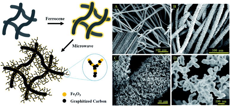
Carbon felt was chosen as the base material here due to its high conductivity, high surface to volume ratio, and excellent chemical and physical stability.30,31 The 3D hierarchical metal oxide–carbon material was fabricated by the microwave pyrolysis of ferrocene deposited on carbon felt. The high microwave absorption capability of carbon felt, due to its relative permittivity and porous structure, which results in a high permeability of microwaves, increased the temperature of the entire volume to 1000 °C uniformly and efficiently.17,32 Ferrocene was decomposed and formed nanostructures on carbon felt in a few seconds.33,34 As shown in the schematic illustration, the carbon felt was immersed in a saturated ferrocene solution in hexane. After drying, the pre-treated carbon felt was pyrolyzed under microwave irradiation at 2.45 GHz for 30 s. This immersion and irradiation process was repeated three times to fully grow the substructures on the carbon felt.The morphology of the original carbon fiber and the resultant structure after microwave irradiation was investigated by scanning electron microscopy (SEM). The average diameter of the original carbon fiber is ∼14 μm (Fig. 1A) with a relatively smooth surface. After microwave heating, closely packed nanostructures grew directly on the carbon fibers, resulting in a rough shrub-like surface with an increase in the average diameter of the fibers to ∼22 μm (Fig. 1B). A hierarchical structure, consisting of micron-sized pores ranging from 20–100 μm and nano-scale pores, hundreds of nanometers in size, was formed (Fig. 1C and D). This topology allowed the microorganism to infiltrate into the interior of the electrode and provided more active electron transfer locations.
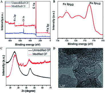
To determine the exact composition of the dendritic nanostructures, the samples were characterized by X-ray photoelectron spectroscopy (XPS) and X-ray powder diffraction (XRD). XPS of the microwave irradiated carbon felt clearly showed peaks corresponding to Fe, C and O, while no Fe was observed for the untreated carbon felt starting material. Furthermore, the associated satellite peak at 719 eV appeared between the two peaks at 725 eV and 711 eV, which can be assigned to Fe 2p1/2 and Fe 2p3/2, respectively, confirmed the presence of Fe2O3 in the nanostructures (Fig. 2A and B).35,36 The peaks at 29.6° and 47.6° in the XRD pattern are associated with the (002) and (101) planes of the graphitized carbon (Fig. 2C)37 and the lamellar sub-structures in the transmission electron microscopy (TEM) image confirm the formation of graphitized carbon (Fig. 2D). The newly appearing reflections seen from 30–40° and in the higher angular region arise from Fe2O3, agreeing well with the XPS results. Overall, the co-existence of graphitized carbon and Fe2O3 in the dendritic nanostructures is confirmed by XPS, XRD and TEM. The hybrid properties of the nano-dendritic materials were further identified by the contrast difference in the TEM image (Fig. S1†).
We postulate a reaction mechanism for the co-formation of graphitized carbon and Fe2O3. Under microwave irradiation, the carbon fibers were rapidly heated to thousands of degrees, far beyond the thermal decomposition temperature of ferrocene. Thus, the ferrocene coated on the carbon fibers decomposed into iron particles and carbonaceous material.38–40 The iron particles catalyzed the carbonization of cyclopentadienyls and yielded graphitized carbon, as well as more iron particles. These products served as new microwave absorbers and further decomposed the ferrocenes to produce more graphitized carbon and iron particles. Therefore, by varying the amount of ferrocene coated onto the fiber and exposure to the microwaves, the degree of surface modification of the carbon felt can be controlled.
Chemical and structural stability are important for the actual use of the electrode materials. The presence of Fe2O3 nanoparticles with the carbon material may also lead to better electron transfer, because of the semi-conductive properties of Fe(III) oxides in microbial extracellular electron transfer.41,42 It is also important to note that the iron oxide-graphitized carbon is quite stable, with no obvious morphological change, as evidenced by scanning electron microscopy (SEM), after sonicating the electrode in water for 30 min (Fig. S2†). Additionally, the high pH value in the cathode chamber (pH ∼ 7.2 medium) should make the dissolution of iron oxide into the solution negligible. The following discussion on the long-term high output of acetate also supports the stability of such iron oxide-carbon materials.
As an electrode in an MES cell, the 3D iron oxide-graphitized carbon felt has the following advantages: (1) a large specific surface area arising from the deposited nanostructure; (2) more adherent points for the microorganism; (3) hierarchically porous structures arising from inter-fibers and inter-nanostructures, which enhance culture media transport and cell penetration; and (4) improvement in microbial extracellular electron transfer mediated by semi-conductive metal oxide nanocolloids.41,42
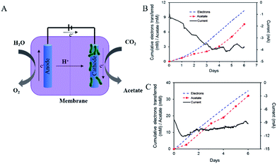
An H-cell device comprising an anode cell, a cathode cell, and a separating membrane was used for microbial electrosynthesis. The microorganism on the cathode extracted electrons from the electrode and reduced CO2 to acetate (Fig. 3A).2,3 The overall net chemical reaction is
As shown in Fig. 3, by using the modified electrode, the efficiency of electrosynthesis increased greatly, in comparison to the unmodified carbon felt. An efficiency of 2.48 × 10⁵ mM per day per m3 for acetate production with 86 ± 9% of the electrons recovered in acetate was achieved using this electrode (Fig. 3B). When carbon felt was used as the cathode, the rate of acetate production was ∼5.19 × 10⁴ mM per day per m3 with a recovery of 73 ± 7% of the electrons in acetate (Fig. 3C). The production of acetate relative to the volume of the electrode was used as a new evaluation criterion, as the volume of the electrode is a more precise measure of the size of the reactor for engineering applications, as opposed to the surface area. In comparison, the modified, hierarchical electrode with the dendritic hybrid metal oxide–carbon nanostructure showed a five-fold increase in acetate production over the carbon felt, further underscoring the efficiency of this electrode geometry for microbial electrosynthesis. As shown in Fig. S3B,† efficient acetate production was maintained with these electrodes for more than 40 days, demonstrating the functional stability of the modified electrode.
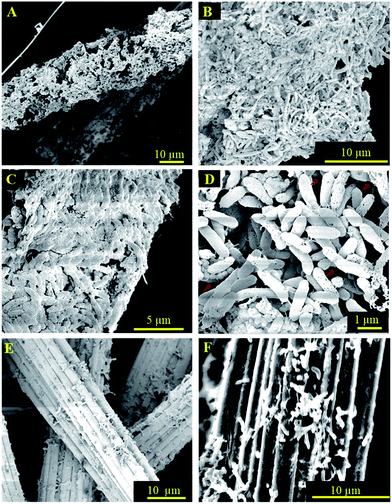
As expected, when the hierarchical electrode was used in the MES cell, where the acetogenic bacterium Sporomusa ovata was the microorganism, a mature biofilm was formed on the electrode that wrapped around the carbon fiber. As shown in Fig. 4A–D, coherent microorganisms attached to the surface and adhered to each other. Even for the internal fibers, a densely packed biofilm was found on the surface (Fig. 4C and D). The optimal wettability of modified carbon felt favors culture media transport and cell penetration. At a higher magnification (Fig. 4D), it appeared that more than a single layer of the biofilm was formed on the deposited layer, as evidenced by the surface roughness. These results demonstrated that the multilevel porous structure of the 3D electrode allowed sufficient culture media exchange to support internal microorganism biofilm growth. As a control, Fig. 4E and F showed that only a few microorganisms attached to the plain carbon fiber, which further suggested that the 3D electrodes with the nanostructured hybrid surface and multi-length scale porosity provided a superior environment for microbial colonization.
Conclusion
In summary, we have developed a functional 3D hierarchically porous electrode by the in situ microwave pyrolysis of ferrocene on carbon felt. This electrode is an attractive candidate for microbial electrosynthesis owing to its high conductivity, increased surface area, interconnected macroporosity, improved electrochemistry and robust mechanical support. The unique character of this 3D electrode provided sufficient space for microbial colonization, culture media transport and improved electroactivity. For the microbial reduction of carbon dioxide by Sporomusa ovata, a five-fold increase in the acetate production rate was achieved with these 3D electrodes in comparison to carbon felt. This simple, rapid and low-cost pyrolysis method can be extended to fabricate other nanostructured architectures for more energy storage devices and electrochemical systems.Acknowledgements
M. Cui and H. Nie contributed equally to this work. The modification of the electrode surface using the hybrid materials was supported by the US Department of Energy, Office of Basic Energy Sciences under contract DE-FG02-96ER45612. The microbial electrosynthesis and the characterization of the device performance were supported by the Advanced Research Projects Agency-Energy (ARPA-E), U.S. Department of Energy [DE-AR0000159]. Use of facilities supported by the NSF-funded MRSEC on Polymers (DMR-0820506) is acknowledged.References
- A. Dai, Nat. Clim. Change, 2013, 3, 52 CrossRef.
- K. P. Nevin, S. A. Hensley, A. E. Franks, Z. M. Summers, J. H. Ou, T. L. Woodard, O. L. Snoeyenbos-West and D. R. Lovley, Appl. Environ. Microbiol., 2011, 77, 2882 CrossRef CAS PubMed.
- K. P. Nevin, T. L. Woodard, A. E. Franks, Z. M. Summers and D. R. Lovley, mBio, 2010, 1, 1 CrossRef PubMed.
- F. Dimroth, T. Roesener, S. Essig, C. Weuffen, A. Wekkeli, E. Oliva, G. Siefer, K. Volz, T. Hannappel, D. Haussler, W. Jager and A. W. Bett, IEEE Journal of Photovoltaics, 2014, 4, 620 CrossRef.
- D. R. Lovley, Annu. Rev. Microbiol., 2012, 66, 391 CrossRef CAS PubMed.
- V. Flexer, J. Chen, B. C. Donose, P. Sherrell, G. G. Wallace and J. Keller, Energy Environ. Sci., 2013, 6, 1291 CAS.
- L. Jourdin, S. Freguia, B. C. Donose, J. Chen, G. G. Wallace, J. Keller and V. Flexer, J. Mater. Chem. A, 2014, 2, 13093 CAS.
- C. W. Marshall, D. E. Ross, E. B. Fichot, R. S. Norman and H. D. May, Environ. Sci. Technol., 2013, 47, 6023 CrossRef CAS PubMed.
- H. R. Nie, T. Zhang, M. M. Cui, H. Y. Lu, D. R. Lovley and T. P. Russell, Phys. Chem. Chem. Phys., 2013, 15, 14290 RSC.
- T. Zhang, H. R. Nie, T. S. Bain, H. Y. Lu, M. M. Cui, O. L. Snoeyenbos-West, A. E. Franks, K. P. Nevin, T. P. Russell and D. R. Lovley, Energy Environ. Sci., 2013, 6, 217 CAS.
- D. S. Bethune, C. H. Kiang, M. S. Devries, G. Gorman, R. Savoy, J. Vazquez and R. Beyers, Nature, 1993, 363, 605 CrossRef CAS.
- T. W. Ebbesen and P. M. Ajayan, Nature, 1992, 358, 220 CrossRef CAS.
- Y. Xia, P. Yang, Y. Sun, Y. Wu, B. Mayers, B. Gates, Y. Yin, F. Kim and Y. Yan, Adv. Mater., 2003, 15, 353 CrossRef CAS.
- S. Chabi, C. Peng, D. Hu and Y. Zhu, Adv. Mater., 2014, 26, 2440 CrossRef CAS PubMed.
- V. Chabot, D. Higgins, A. Yu, X. Xiao, Z. Chen and J. Zhang, Energy Environ. Sci., 2014, 7, 1564–1596 CAS.
- W. Chen, Y. Huang, D. Li, H. Yu and L. Yan, RSC Adv., 2014, 4, 21619 RSC.
- C. Cho and J. Moon, Adv. Mater., 2011, 23, 2971 CrossRef CAS PubMed.
- Y. Feng, Q. Yang, X. Wang and B. E. Logan, J. Power Sources, 2010, 195, 1841 CrossRef CAS.
- X. Lang, A. Hirata, T. Fujita and M. Chen, Nat. Nanotechnol., 2011, 6, 232 CrossRef CAS PubMed.
- Z. Niu, P. Luan, Q. Shao, H. Dong, J. Li, J. Chen, D. Zhao, L. Cai, W. Zhou, X. Chen and S. Xie, Energy Environ. Sci., 2012, 5, 8726 CAS.
- G. Oltean, H. D. Asfaw, L. Nyholm and K. Edstrom, ECS Electrochem. Lett., 2014, 3, A54 CrossRef CAS.
- A. L. M. Reddy, S. R. Gowda, M. M. Shaijumon and P. M. Ajayan, Adv. Mater., 2012, 24, 5045 CrossRef CAS PubMed.
- X. Xie, M. Ye, L. Hu, N. Liu, J. R. McDonough, W. Chen, H. N. Alshareef, C. S. Criddle and Y. Cui, Energy Environ. Sci., 2012, 5, 5265–5270 CAS.
- X. Xie, L. Hu, M. Pasta, G. F. Wells, D. Kong, C. S. Criddle and Y. Cui, Nano Lett., 2010, 11, 291–296 CrossRef PubMed.
- X. Wang, G. Li, Z. Chen, V. Augustyn, X. Ma, G. Wang, B. Dunn and Y. Lu, Adv. Energy Mater., 2011, 1, 1089–1093 CrossRef CAS.
- M. Min, K. Machida, J. H. Jang and K. Naoi, J. Electrochem. Soc., 2006, 153, A334–A338 CrossRef CAS.
- T. Chen, Z. Cai, Z. Yang, L. Li, X. Sun, T. Huang, A. Yu, H. G. Kia and H. Peng, Adv. Mater., 2011, 23, 4620–4625 CrossRef CAS PubMed.
- J. M. Haag, G. Pattanaik and M. F. Durstock, Adv. Mater., 2013, 25, 3238–3243 CrossRef CAS PubMed.
- D. Ma, Z. Cao, H. Wang, X. Huang, L. Wang and X. Zhang, Energy Environ. Sci., 2012, 5, 8538–8542 CAS.
- Z. Lv, D. Xie, X. Yue, C. Feng and C. Wei, J. Power Sources, 2012, 210, 26 CrossRef CAS.
- M. Zhou, M. Chi, J. Luo, H. He and T. Jin, J. Power Sources, 2011, 196, 4427 CrossRef CAS.
- F. Chemat and M. Poux, Tetrahedron Lett., 2001, 42, 3693 CrossRef CAS.
- Z. Liu, J. Wang, V. Kushvaha, S. Poyraz, H. Tippur, S. Park, M. Kim, Y. Liu, J. Bar, H. Chen and X. Zhang, Chem. Commun., 2011, 47, 9912 RSC.
- H. Nie, M. Cui and T. P. Russell, Chem. Commun., 2013, 49, 5159 RSC.
- T. Fujii, F. M. F. de Groot, G. A. Sawatzky, F. C. Voogt, T. Hibma and K. Okada, Phys. Rev. B: Condens. Matter Mater. Phys., 1999, 59, 3195 CrossRef CAS.
- A. P. Grosvenor, B. A. Kobe, M. C. Biesinger and N. S. McIntyre, Surf. Interface Anal., 2004, 36, 1564 CrossRef CAS.
- S. Yuan, Z. Zhou and G. Li, CrystEngComm, 2011, 13, 4709 RSC.
- S. E. Iyuke, T. A. Mamvura, K. Liu, V. Sibanda, M. Meyyappan and V. K. Varadan, Nanotechnology, 2009, 20, 375602 CrossRef CAS PubMed.
- H. Lin, H. Zhu, H. Guo and L. Yu, Mater. Lett., 2007, 61, 3547 CrossRef CAS.
- N. M. Mubarak, J. N. Sahu, E. C. Abdullah, N. S. Jayakumar and P. Ganesan, Diamond Relat. Mater., 2014, 48, 52 CrossRef CAS.
- R. Nakamura, F. Kai, A. Okamoto, G. J. Newton and K. Hashimoto, Angew. Chem., Int. Ed., 2009, 48, 508 CrossRef CAS PubMed.
- R. Nakamura, F. Kai, A. Okamoto and K. Hashimoto, J. Mater. Chem. A, 2013, 1, 5148 CAS.
Footnote |
| † Electronic supplementary information (ESI) available. See DOI: 10.1039/c7se00073a |
| This journal is © The Royal Society of Chemistry 2017 |


