A novel porous sulfonated poly(ether ether ketone)-based multi-layer composite membrane for proton exchange membrane fuel cell application†
Yongyi
Jiang
ab,
Jinkai
Hao
ab,
Ming
Hou
 *a,
Shaojing
Hong
ab,
Wei
Song
a,
Baolian
Yi
a and
Zhigang
Shao
 *a
*a
aFuel Cell System and Engineering Laboratory, Dalian Institute of Chemical Physics, Chinese Academy of Sciences, 457 Zhongshan Road, Dalian 116023, China. E-mail: houming@dicp.ac.cn; zhgshao@dicp.ac.cn
bUniversity of Chinese Academy of Sciences, Beijing 100039, China
First published on 20th June 2017
Abstract
An advanced sulfonated poly(ether ether ketone) (sPEEK)-based multi-layer composite membrane with high performance and durability is fabricated, which consists of a porous sPEEK base membrane, two transition layers (TLs) and two PFSA outer layers (PLs). These porous sPEEK base membranes with nanoscale pores are prepared first through a vapor induced phase inversion (VIPI) method. Owing to the higher porosity and the denser distribution of sulfonic acid clusters, the cell performance and physical properties of porous sPEEK membranes are superior to those of sPEEK membranes prepared by a solvent casting method. The multi-layer structure of this composite membrane results in reduced swelling and improved water uptake, and eventually brings about a high proton conductivity. Single cell tests indicate that the multi-layer composite membrane has a higher cell performance and more outstanding durability in comparison with sPEEK membranes. The growth rate of hydrogen crossover current density of this composite membrane is much lower than that of sPEEK membranes, proving the effectiveness of PLs in improving the chemical durability of sPEEK-base membranes. After long-term stability tests, the sPEEK multi-layer composite membrane still shows a good cell performance, especially at low relative humidity (RH).
Introduction
Research on proton exchange membranes (PEMs), especially on high performance and low-cost PEMs, is always the focus in the low temperature PEMFC (LT-PEMFC) field.1–3 Perfluorosulfonic acid (PFSA) ionomer membranes, in particular the Nafion® type, are the state-of-the-art PEMs due to their excellent performances and stabilities in low temperature PEMFCs (around or below 80 °C).4 However, their high cost is still a major obstacle to the widespread use of LT-PEMFCs.Over the last few decades, many hydrocarbon polymer materials, including polystyrene-sulfonic acid (PSSA),5 poly(arylene ether)s (PAEs),6,7 polysulfones8,9 and their derivatives, etc.,10,11 have been studied as PEMs. As a typical kind of PAE, sulfonated poly(ether ether ketones) (sPEEKs) have a rigid polymer main chain of a polyaromatic backbone with many short side chains of sulfonic acid groups, and are considered to be a promising candidate for alternative PEM materials owing to their low-cost, good gas barrier properties, high thermal stability and mechanical strength.12,13 Recently, improvement on sPEEK-base membranes involves modification with other polymers,14,15 or formation of cross-linked networks by functional groups,16,17 and blending inorganic fillers into PEMs.18–20 However, the common sPEEK membranes, prepared by a conventional solvent casting method, have a limited proton conductivity and cell performance unless their degree of sulfonation (DS) is improved to some extent, which brings about the dramatic swelling of sPEEK.10,21,22
Another challenge that remains is that sPEEKs are prone to chemical degradation, so they cannot withstand long-term use under PEMFC operations. Gonon et al. considered that the degradation of sPAEK membranes initially occurred in non-sulfonated phenyl ether aromatic rings resulting from the attack of hydroxyl radicals, and further caused scissions in the sPAEK main chain.23 Zhang et al. confirmed the above degradation mechanism through investigating the degradation behavior of sulfonated PEEK under strongly acidic and oxidizing conditions.24 Furthermore, Zhao et al.25 investigated the degradation mechanism of hydrocarbon ionomers for PEMFCs using density functional theory (DFT), and pointed out that the aryl sulfonated bond and the aryl ether bond are two possible weak sites susceptible to OH radical attack.
There have been some research studies on the chemical durability of hydrocarbon polymer membranes in a PEMFC environment. Several approaches can be summarized. One is to add a free radical scavenger,26–28 such as CeO2, MnO2 and vitamin E, or other nanocomposites,29–31 which can scavenge reactive oxygen species (ROS) or decrease gas crossover. Another is to synthesise a novel PAE derivative by reducing the electron density of the polymer backbone by attaching bulky steric groups,32 or introducing strong electron withdrawing groups.33 Sulfonated PAEKs with a cross-linked structure also had a higher chemical stability.7,17,34 Lee et al.34 considered that this semi-interpenetrating polymer network resulting from cross-linking decreased the hydrogen crossover evidently and promoted the chemical stability of fuel cells. Apart from these, bi-layer and multi-layer composite membranes are an effective strategy to obtain high durability of PEMs, especially for sulfonated hydrocarbon materials.35–38 Lien and Lee et al.39 prepared a novel sulfonated polyimide/Nafion multi-layer membrane, in which Nafion layers were adhered to either side of the SPI by thermal imidization, and durability tests revealed a relatively improved stability compared to that of native SPI. Watanabe et al.38 reported a bi-layer ionomer membrane, a thin-layer Nafion on a sulfonated aromatic copolymer (SPK-bl-1), which exhibited a higher cell performance despite no significant change of water uptake and proton conductivity compared with the original SPK-bl-1 membrane, but long-term durability was not involved.
In this paper we designed an advanced sPEEK-based multi-layer composite membrane consisting of a porous sPEEK base membrane, two transition layers (TLs) and two PFSA outer layers (PLs). PLs formed by PFSA act as protective layers, which can protect the inner sPEEK base membrane against oxidation degradation from reactive oxygen species such as hydrogen peroxide, hydroxyl and hydroperoxyl radicals.40,41 TLs are fabricated by the mixture of PFSA and sPEEK. Owing to the hydrogen bond from the sulfonic acid groups of sPEEK and PFSA, TLs improve the interfacial compatibility between the sPEEK base membrane and PLs effectively as well as mitigate the delamination problem of the composite membranes.42
Here, the porous sPEEK base membrane with nanoscale pores was prepared by using a vapor induced phase inversion (VIPI) method, which was scarcely reported. During the VIPI process, dibutyl phthalate (DBP), a pore-forming additive with a low molecular weight,43 was added to form the nanoscale pores and adjust the porosity of the porous sPEEK membranes. It was reported that the porous sPEEK membrane had an advantage over the membrane prepared by a solvent casting method in terms of the cell performance and physical properties. Based on this, a sPEEK-based multi-layer composite membrane was prepared and investigated. Its long-term stability under accelerated PEMFC operations was also studied.
Experimental
The source of materials and chemicals used in this study and membrane characterization are included in the ESI.†PEEK sulfonation
sPEEK was prepared by the post-sulfonation method.44–46 8 g of PEEK powder was dissolved in 100 mL sulfuric acid (95–98 wt%) in a three-neck flask with a vigorous mechanical agitation under a nitrogen atmosphere. The sulfonation reaction was carried out at 65 °C for two hours. After that, this sulfonation reaction was terminated through precipitating the polymer solution into deionized (DI) water, and then washed with DI water several times until the pH of the rinse water was in the range of 6–7. Subsequently, the sPEEK polymer was dried at 50 °C for several hours, and further dried at 100 °C for 12 h. The DS of the sPEEK polymer was determined to be 0.65 by 1H NMR spectroscopy (Fig. S1, ESI†).44,45Membrane preparation
The fabrication process of the sPEEK multi-layer composite membrane is illustrated in Scheme 1.Firstly, porous sPEEK membranes were prepared through a vapor induced phase inversion (VIPI) method.47 Specially, the prepared sPEEK was dissolved in DMAc to obtain 16 wt% sPEEK solution. Then the sPEEK solution was cast onto a glass plate and placed it in a constant temperature and humidity chamber at 50 °C and 60% relative humidity (RH) for 0.5 h. After that, the membrane was peeled off from the above glass plate, and washed with the mixture of water–ethanol and DI water several times. During the VIPI process, different amounts of DBP, such as 0 wt%, 0.5 wt% and 1.0 wt%, were added into the above sPEEK solution to improve the porosity of the porous sPEEK membranes. The corresponding sPEEK membranes were named SP2, SP3 and 3P4 membrane, respectively.
Secondly, indirect hot-spraying was used to fabricate PLs and TLs on the surface of silicon substrates by spraying Nafion dispersion and the solution mixture. Finally, the sPEEK multi-layer composite membrane was prepared by a thermal transfer method via sandwiching the prepared sPEEK membrane between two silicon substrates at 130 °C and 0.4 MPa. The solution mixture was made up of 5 wt% Nafion dispersion and 5 wt% sPEEK solution with the ratio of 1![[thin space (1/6-em)]](https://www.rsc.org/images/entities/char_2009.gif) :
:![[thin space (1/6-em)]](https://www.rsc.org/images/entities/char_2009.gif) 1. The amounts of solution mixture for TLs and Nafion dispersion for PLs were 8.5 μL cm−2 and 20 μL cm−2, respectively.
1. The amounts of solution mixture for TLs and Nafion dispersion for PLs were 8.5 μL cm−2 and 20 μL cm−2, respectively.
As a comparison, the sPEEK membrane prepared by using the solvent casting method was named the SP1 membrane. The thickness of all pure sPEEK membranes was 16–17 μm and that of the sPEEK multi-layer composite membrane was controlled to be 24 ± 2 μm and was marked as SP3–NF.
Membrane characterization
The physical properties of the porous sPEEK membranes were characterized, such as the porosity, water uptake (WU) and swelling ratio. Fourier Transform Infrared Spectroscopy (FTIR), thermogravimetric analysis (TGA) and proton conductivity measurements of the membranes and scanning electron microscopy (SEM) and transmission electron microscopy (TEM) were performed. All of the detailed experimental procedures are also included in the ESI.†Assembly of fuel cell and performance tests
Membrane electrode assemblies (MEAs) were fabricated through sandwiching the membrane between gas diffusion electrodes (0.5 mg Pt per cm2 for the cathode and 0.3 mg Pt per cm2 for the anode). The effective area of the MEAs was 5 cm2. The fabricated MEAs were first activated by feeding H2 and O2 at 65 °C for several hours. I–V curves were recorded using a fuel cell impedance meter (KFM2030, Kikusui, Japan) at 65 °C and different RHs with 0.1/0.2 L min−1 of H2/O2.The long-term stability of the sPEEK multi-layer composite membrane was evaluated by constant-current tests using an electric load PLZ152WA (Kikusui, Japan). During these stability tests, the flow rates of H2 and O2 with 30% RH were 0.06/0.1 L min−1, respectively. At the same time, the linear sweep voltammetry (LSV) method was performed to record the H2 crossover current density using a Solartron SI 1287 equipped with a potentiostat 1260 frequency response analyzer.
Results and discussion
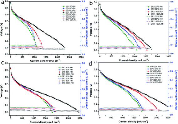
Before investigating this sPEEK-based multi-layer composite membrane, we explored first the cell performance of the sPEEK base membrane. Fig. 1a–d show the I–V performance of the MEAs fabricated with the SP1 membrane (denoted as SP1 MEA) and porous sPEEK membranes. It was observed that these porous sPEEK MEAs exhibited a better I–V performance than the SP1 MEA regardless of the open circuit voltage (OCV) and hydrogen crossover, especially at high relative humidity (RH). The cell performance of the porous sPEEK membranes increased with the increasing amount of DBP (from SP2 to SP4). In addition, the SP1 MEA showed a slightly higher ohmic resistance compared to the porous sPEEK MEA at inadequate humidification, whereas all of the membranes showed a similar ohmic resistance at 100% RH. The high cell performance of SP3 and SP4 membranes might be attributed to their porous structure which helped to keep more water and improve the proton conductivity.A comparison of OCV and hydrogen crossover current density for these MEAs is shown in Fig. S2 (ESI),† and Table 1 also lists the addition amount of DBP, porosity, OCV and hydrogen crossover current density of the sPEEK membranes. It was seen that SP1 prepared by the solvent casting method had the highest OCV value (0.986 V) and the lowest hydrogen crossover current density (1.92 mA cm−2), agreeing with its dense structure. The porosity of SP2, SP3 and SP4 was 63.5%, 71.7% and 73.9%, respectively. It showed an increasing trend with the increasing amount of DBP, coupling with the decrease of OCV and the corresponding increase of H2 crossover current density. The OCV of SP4 was just 0.886 V and its hydrogen crossover current density reached 26 mA cm−2. High gas crossover resulted from high porosity, so SP2 and SP3 had higher OCV and lower H2 crossover current density than SP4 due to their lower porosity. Therefore, we concluded that (i) the higher porosity caused by the addition of DBP could bring about higher gas crossover, leading to decreased OCV and increased H2 crossover current density. (ii) The porous sPEEK membrane with high porosity had an outstanding cell performance regardless of the OCV and H2 crossover.
| Membrane | SP1a | SP2 | SP3 | SP4 |
|---|---|---|---|---|
| a SP1 membrane prepared by the solvent casting method without DBP addition. b The OCV data testing at 65 °C and 100% RH. c Hydrogen crossover current density testing at 65 °C and 100% RH. | ||||
| DBP amount (wt%) | — | 0.0 | 0.5 | 1.0 |
| Porosity (%) | — | 63.5 | 71.7 | 73.9 |
| OCVb (V) | 0.986 | 0.968 | 0.930 | 0.886 |
| Hydrogen crossover (mA cm−2)c | 1.92 | 3.96 | 4.4 | 26 |
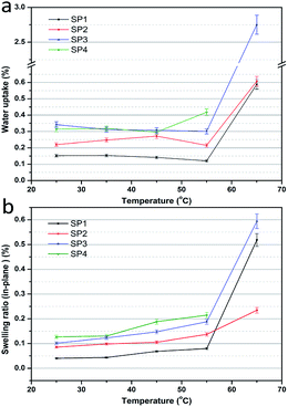
The water uptake and swelling ratio are of importance for PEMs, which have a significant influence on the proton conductivity and dimensional stability.48Fig. 2 shows the water uptake and swelling ratio of these sPEEK membranes. In Fig. 2a, the porous sPEEK membranes showed a higher water content than SP1. This was explained by the porous structure which facilitated the collection of more water in the porous sPEEK membrane and promoted the proton transport. Additionally, the water uptake of porous sPEEK membranes, from SP2 to SP4, tends to increase with the increasing amount of DBP. It was noteworthy that the water uptake exhibited a slight difference when the testing temperature ranged from 25 °C to 55 °C. Once the temperature reached or exceeded 65 °C, a dramatic increase of water uptake had taken place, especially for SP4, so the water uptake and swelling ratio were not measured properly. The swelling ratio of the above membranes exhibited a similar result to the water uptake in Fig. 2b. When taking into account the initial cell performance and physical properties of the above membranes, we found that (i) although SP4 had a higher cell performance, the higher water uptake and swelling ratio at elevated temperatures hindered the use of SP4. (ii) SP2 had a better swelling ratio compared to sPEEK membranes, but its cell performance was low. So, SP3 was used as the base membrane for the following research.
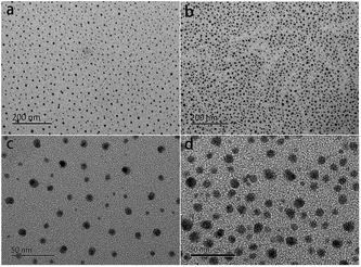
The distribution of sulfonic acid groups of the sPEEK membranes stained with silver ions was characterized by TEM. In comparison with Nafion, the sPEEK membrane has a similar micro-phase separation structure, which is closely associated with water uptake and proton conductivity and further influences the PEMFC performance.49,50 In the TEM images (Fig. 3), the dark spots were hydrophilic domains formed by sulfonic acid clusters, while the bright regions represented the hydrophobic domains composed of polymer backbones.51,52 As shown in Fig. 3a and b, both SP1 and SP3 displayed a homogeneous dispersion of sulfonic acid clusters, but SP3 had denser ion clusters. Fig. 3c and d are the high magnification images of SP1 and SP3, respectively. The size of sulfonic acid clusters in SP3 was 8–11 nm, which was larger than that of SP1 (7 ± 2 nm). The larger sulfonic acid clusters as well as the denser distribution in SP3 contributed to higher water uptake and proton conductivity, and eventually improved the PEMFC performance, which were in accordance with the previous results.
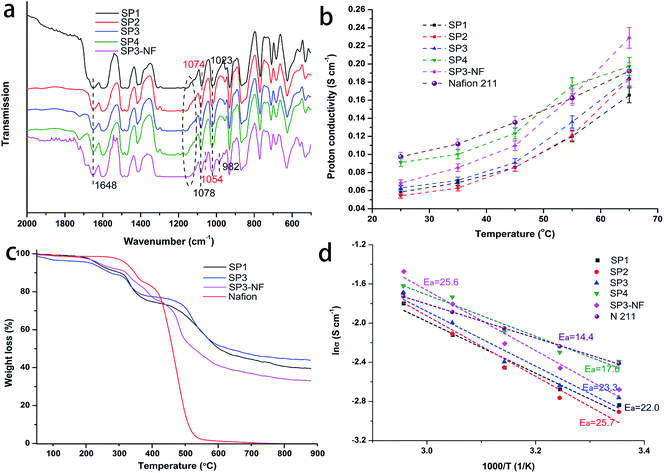
The FTIR spectra of the sPEEK base membranes and SP3–NF composite membrane are shown in Fig. 4a. In the spectrum of sPEEK, the typical absorption peak at 1648 cm−1 corresponded to the carbonyl group (C![[double bond, length as m-dash]](https://www.rsc.org/images/entities/char_e001.gif) O), and the peaks at 1023 and 1074–1078 cm−1 were assigned to asymmetric and symmetric stretching vibrations of O
O), and the peaks at 1023 and 1074–1078 cm−1 were assigned to asymmetric and symmetric stretching vibrations of O![[double bond, length as m-dash]](https://www.rsc.org/images/entities/char_e001.gif) S
S![[double bond, length as m-dash]](https://www.rsc.org/images/entities/char_e001.gif) O.44,53,54 Additionally, the peaks at 1074 cm−1 and 1078 cm−1 were associated with SP1 and porous sPEEK membranes, respectively, which might have resulted from the variation of the pore structure. SP3–NF had a similar infrared absorption to sPEEK membranes except for the peaks at 982 cm−1 and 1054 cm−1 assigned to the stretching vibration of C–O–C and the symmetric stretching vibration of the –SO3– group in the side chain of PFSA, respectively.55,56 The absorption peak of ether groups (Ar–O–Ar), marked with the black-dotted line in Fig. 4a, shifted from 1150 cm−1 to 1130 cm−1. The reason was attributed to the influence of the PFSA ionomer on sPEEK. Therefore, the chemical interaction among TLs, PLs and sPEEK base membranes was confirmed due to the hydrogen bond from sulfonic acid groups of PFSA and sPEEK, which also indicated the effectiveness of TLs in improving the interfacial compatibility between sPEEK base membranes and PLs.
O.44,53,54 Additionally, the peaks at 1074 cm−1 and 1078 cm−1 were associated with SP1 and porous sPEEK membranes, respectively, which might have resulted from the variation of the pore structure. SP3–NF had a similar infrared absorption to sPEEK membranes except for the peaks at 982 cm−1 and 1054 cm−1 assigned to the stretching vibration of C–O–C and the symmetric stretching vibration of the –SO3– group in the side chain of PFSA, respectively.55,56 The absorption peak of ether groups (Ar–O–Ar), marked with the black-dotted line in Fig. 4a, shifted from 1150 cm−1 to 1130 cm−1. The reason was attributed to the influence of the PFSA ionomer on sPEEK. Therefore, the chemical interaction among TLs, PLs and sPEEK base membranes was confirmed due to the hydrogen bond from sulfonic acid groups of PFSA and sPEEK, which also indicated the effectiveness of TLs in improving the interfacial compatibility between sPEEK base membranes and PLs.
The proton conductivity of the PEMs has a vital influence on the PEMFC performance. Fig. 4b shows the proton conductivity of the membranes, in which all of the membranes exhibit increasing proton conductivity with the increase of temperature. At the same time, the proton conductivity of the porous sPEEK membranes tended to increase with increasing porosity, and their value was superior to that of SP1, especially for SP3 and SP4. Additionally, SP3–NF had a higher proton conductivity compared to SP3. At 25 °C, the proton conductivity of SP3 was 0.058 S cm−1, but that of SP3–NF reached 0.068 S cm−1. Higher proton conductivity was observed in Nafion 211. While the testing temperature increased to 65 °C, the proton conductivity of SP3–NF could even surpass that of Nafion 211, which was attributed to the multi-layer composite structure of SP3–NF.
Fig. 4d shows the corresponding Arrhenius plots for the proton conductivity of the membranes, and their activation energy (Ea) for proton transport in the membranes is calculated and represented as well. It was seen that the Ea of Nafion 211 was 14.4 kJ mol−1, and all of the sPEEK membranes and SP3–NF had a higher Ea than 14 kJ mol−1, which agreed with that of the Grotthuss mechanism which was reported to be around 14–40 kJ mol−1,57 that is to say, the proton transport mainly took place via the Grotthuss mechanism where the protons transfer from one solvent molecule to another through the hydrogen bonds. Shukla et al. considered that the proton transport via the former was faster than the diffusion of water (vehicular mechanism) due to the presence of high water uptake.58 The above also explained the higher proton conductivity of SP3–NF. As mentioned above, high porosity resulted in high water uptake which promoted proton transport, but the corresponding swelling also increased. Here, as shown in Fig. S3 (ESI),† SP3–NF achieved an improved water uptake and a reduced swelling ratio due to the presence of a multi-layer structure, which contributed to an elevated proton conductivity.
Fig. 4c shows TGA curves of four membrane samples. It was seen that Nafion showed a two-step weight loss pattern.59 The first weight loss started around 280 °C, which was attributed to the splitting-off of sulfonic acid groups on Nafion side-chains. The second weight loss occurred above 355 °C, which was attributed to the decomposition of the main chains. SP1 and SP3 exhibited a three-step weight loss.60 The first weight loss was before 250 °C attributed to the dehydration of absorbed water or the evaporation of residual DMAc. The second and the third weight loss were the loss of sulfonic acid and the main chain decomposition of sPEEK, respectively, which started at around 320 °C and 480 °C. It was noteworthy that the SP3–NF composite membrane showed a similar degradation process compared to SP1 and SP3 in spite of a small change in the temperature of weight loss. At 550 °C, the residual weight of SP3–NF (48 wt%) was much higher than that of Nafion, demonstrating the outstanding thermal stability of the SP3–NF composite membrane.
The cross-sectional structure and surface morphology of the SP3–NF multi-layer composite membrane were characterized by SEM. As shown in Fig. 5a, the multi-layer structure of the sPEEK composite membrane was observed and it agreed with the EDS linear scanning of fluorine (F) element in the cross section (Fig. 5c). The thickness of the sPEEK base membrane is 16–17 μm, and the thickness of TLs and PLs is about 1 μm and 4 μm, respectively. So, the lower cost of SP3–NF can be achieved due to the lower content of Nafion. At the same time, a good contact among layers of SP3–NF indicates the effectiveness of TLs in improving the interfacial compatibility between sPEEK base membranes and PLs. Fig. 5b shows the high magnification image of the sPEEK base membrane in SP3–NF. It was observed that the sPEEK base membrane prepared by the VIPI method had nanoscale pores, not microscale pores. Additionally, the dense surface morphology of the SP3–NF multi-layer composite membrane is observed in Fig. 5d, which contributed to mitigating the gas crossover caused by the porosity of the sPEEK base membrane.
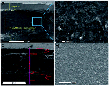 | ||
| Fig. 5 SEM images of the SP3–NF multi-layer composite membrane: (a and b) the cross section; (d) the surface; (c) EDS linear scanning analysis of fluorine element in the cross section. | ||
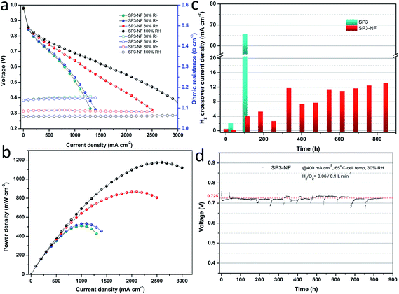
Fig. 6a shows the I–V curves and ohmic resistance of the MEA fabricated with the SP3–NF multi-layer composite membrane (SP3–NF MEA) at different humidity levels, and the corresponding power density curves are given in Fig. 6b. It was found that the SP3–NF MEA exhibited a higher cell performance than the SP3 MEA (Fig. 1c), especially at 80% RH and 100% RH. The OCV of the SP3 MEA at 100% RH was 0.92 V, but the value of the SP3–NF MEA increased to 0.96 V. In comparison with that of the SP3 MEA, the maximum power density of the SP3–NF MEA increased by 23% (867 mW cm−2) and 17% (1176 mW cm−2) at 80% RH and 100% RH, respectively. It is indicated that the introduction of the multi-layer composite structure effectively improves the cell performance of SP3 and brings about an elevated OCV, mitigating the gas leakage from the porous sPEEK base membrane.
In addition to high cell performance, long-term stability is also a vital factor for the practical use of PEMs.61,62 Generally, chemical degradation of PEMs will happen during long-term cell operations, coupled with mechanical degradation.59,63,64 Humidity changes usually lead to the aggravated mechanical degradation of PEMs, while low RH operation (inadequate humidification) always brings about the accelerated failure of PEMFCs due to the severe chemical degradation of PEMs.65 Considering this, during the stability tests the cell temperature of 65 °C and the gases supplied with 30% RH were provided with an aim to accelerate the chemical degradation of PEMs, lowering the influence of mechanical degradation.
Fig. 6c compares the hydrogen crossover current density between the SP3 MEA and SP3–NF MEA. The initial H2 crossover current densities of the SP3 MEA and SP3–NF MEA were 0.5 and 0.46 mA cm−2, respectively. Afterwards, the H2 crossover of the SP3 MEA exhibited a sharp growth. Its value increased 3-fold after 24 h, and reached 65.6 mA cm−2 after 100 h. However, the H2 crossover of the SP3–NF MEA showed a slow growth, and its value was just 3.96 mA cm−2 after 113 h. During the whole tests, the growth rate of H2 crossover current density for the SP3–NF MEA was 12.5 μA cm−2 h−1 approximately, which was much lower than that of the SP3 MEA. Fig. 6d exhibits the long-term voltage data of the SP3–NF MEA at 400 mA cm−2 and 30% RH, indicating an outstanding stability of voltage. The initial upward tail of voltage data was attributed to the full humidification of the SP3–NF MEA. Afterwards, the humidity was kept at a low level, and the oxygen partial pressure was also at a lower level after hydrogen crossover tests, which accounted for the downward tails in the subsequent stability tests. The results proved that the SP3–NF composite membrane not only has a higher cell performance, but also achieves an improved durability compared to SP3.
The I–V performance and power density curves of the SP3–NF MEA at different RHs before and after the stability tests were characterized. In Fig. 7a, the I–V performance of the SP3–NF MEA at 80% RH increased after the stability test of 40 h, and a slight decrease was observed after 845 h. There was little change in the ohmic resistance of the SP3–NF MEA. However, the maximum power density (Fig. 7b) of the SP3–NF MEA increased by 5.4% (914 mW cm−2) after 40 h, but decreased by 15% (738 mW cm−2) after 845 h. At the same time, the OCV of the SP3–NF MEA also decreased. In addition, the I–V performance of the SP3–NF MEA at 50% RH and 100% RH is given in Fig. S4 and S5 (ESI),† respectively. Even after 845 h stability tests at low RH, the SP3–NF MEA displayed a better I–V performance at 50% RH, and its maximum power density reached 651 mW cm−2. When the RH was promoted to 100% RH, the polarization performance of the SP3–NF MEA showed a decrease to some extent. Nevertheless, the SP3–NF membrane still exhibits a satisfactory result.
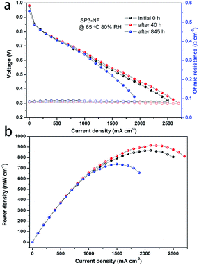 | ||
| Fig. 7 (a) I–V performance and ohmic resistance (open symbol) and (b) corresponding power density of the MEA fabricated with the SP3–NF composite membrane during stability tests at 65 °C and 80% RH. | ||
Conclusion
We fabricate a novel porous sPEEK-based multi-layer composite membrane with high performance and long-term durability, which consists of a porous sPEEK base membrane, two TLs and two PLs. The porous sPEEK membrane with nanoscale pores is realized first by using a VIPI method. Owing to the higher porosity and the denser distribution of sulfonic acid clusters, porous sPEEK membranes have an advantage over sPEEK membranes prepared by solvent casting in terms of cell performance and physical properties. SEM tests indicate that this multi-layer composite membrane has an obvious multi-layer structure which can enhance water uptake, restrict swelling and promote the proton conductivity eventually. The thin PLs and TLs indicate a lower cost for this multi-layer composite membrane due to the lower content of Nafion. Additionally, single cell tests for the SP3–NF MEA show higher cell performance than the SP3 MEA. The outstanding durability of the SP3–NF multi-layer composite membrane is confirmed by long-term stability tests under accelerated PEMFC operations. The growth rate of H2 crossover current density for the SP3–NF MEA (12.5 μA cm−2 h−1) was much lower than that of the SP3 MEA. This demonstrates that this multi-layer composite strategy has a remarkable effectiveness in improving the chemical stability of sPEEK-base membranes. Consequently, we conclude that high performance and high durability PEMs can be achieved by the multi-layer composite strategy. This advanced sPEEK-based multi-layer composite membrane exhibits huge potential as an alternative PEM for PEMFC application.Acknowledgements
This work was financially supported by the National Key Technology Support Program (No. 2015BAG06B00) and the Major Program of the National Natural Science Foundation of China (No. 61433013).References
- R. Devanathan, Energy Environ. Sci., 2008, 1, 101–119 CAS.
- H. W. Zhang and P. K. Shen, Chem. Rev., 2012, 112, 2780–2832 CrossRef CAS PubMed.
- A. Kraytsberg and Y. Ein-Eli, Energy Fuels, 2014, 28, 7303–7330 CrossRef CAS.
- H. Zhang and P. K. Shen, Chem. Soc. Rev., 2012, 41, 2382–2394 RSC.
- J. Byun, J. Sauk and H. Kim, Int. J. Hydrogen Energy, 2009, 34, 6437–6442 CrossRef CAS.
- H. Q. Li, X. J. Liu, J. Xu, D. Xu, H. Ni, S. Wang and Z. Wang, J. Membr. Sci., 2016, 509, 173–181 CrossRef CAS.
- L. Zhang, D. Qi, C. Zhao and H. Na, J. Membr. Sci., 2016, 508, 15–21 CrossRef CAS.
- C. Zhang, X. Zhuang, X. Li, W. Wang, B. Cheng, W. Kang, Z. Cai and M. Li, Carbohydr. Polym., 2016, 140, 195–201 CrossRef CAS PubMed.
- R. L. Thankamony, M. Won and T.-H. Kim, Int. J. Hydrogen Energy, 2013, 38, 5084–5091 CrossRef CAS.
- A. Iulianelli and A. Basile, Int. J. Hydrogen Energy, 2012, 37, 15241–15255 CrossRef CAS.
- S. Bose, T. Kuila, N. Thi Xuan Lien, N. H. Kim, K.-t. Lau and J. H. Lee, Prog. Polym. Sci., 2011, 36, 813–843 CrossRef CAS.
- D. E. Curtin, R. D. Lousenberg, T. J. Henry, P. C. Tangeman and M. E. Tisack, J. Power Sources, 2004, 131, 41–48 CrossRef CAS.
- V. A. Sethuraman, J. W. Weidner, A. T. Haug, S. Motupally and L. V. Protsailo, J. Electrochem. Soc., 2008, 155, B50–B57 CrossRef CAS.
- A. R. Kim, M. Vinothkannan and D. J. Yoo, Int. J. Hydrogen Energy, 2017, 42, 4349–4365 CrossRef CAS.
- E. Sgreccia, M. L. Di Vona and P. Knauth, Int. J. Hydrogen Energy, 2011, 36, 8063–8069 CrossRef CAS.
- Y. Dong, Y.-X. Zhang, H.-L. Xu, T.-W. Luo, F.-Y. Fu and C.-J. Zhu, J. Appl. Polym. Sci., 2016, 133, 43492–43500 Search PubMed.
- L. Lei, X. Zhu, J. Xu, H. Qian, Z. Zou and H. Yang, J. Power Sources, 2017, 350, 41–48 CrossRef CAS.
- K. H. Oh, D. Lee, M. J. Choo, K. H. Park, S. Jeon, S. H. Hong, J. K. Park and J. W. Choi, ACS Appl. Mater. Interfaces, 2014, 6, 7751–7758 CAS.
- X. Qiu, T. Dong, M. Ueda, X. Zhang and L. Wang, J. Membr. Sci., 2017, 524, 663–672 CrossRef CAS.
- H. Cai, X. Wu, Q. Wu, F. Cao and W. Yan, RSC Adv., 2016, 6, 84689–84693 RSC.
- S. Feng, G. Wang, H. Zhang and J. Pang, J. Mater. Chem. A, 2015, 3, 12698–12708 CAS.
- D. J. Kim, D. H. Choi, C. H. Park and S. Y. Nam, Int. J. Hydrogen Energy, 2016, 41, 5793–5802 CrossRef CAS.
- C. Perrot, L. Gonon, M. Bardet, C. Marestin, A. Pierre-Bayle and G. Gebel, Polymer, 2009, 50, 1671–1681 CrossRef CAS.
- Z. Z. Yuan, X. F. Li, J. B. Hu, W. X. Xu, J. Y. Cao and H. M. Zhang, Phys. Chem. Chem. Phys., 2014, 16, 19841–19847 RSC.
- Y.-y. Zhao, E. Tsuchida, Y.-K. Choe, J. Wang, T. Ikeshoji and A. Ohira, J. Membr. Sci., 2015, 487, 229–239 CrossRef CAS.
- B. P. Pearman, N. Mohajeri, R. P. Brooker, M. P. Rodgers, D. K. Slattery, M. D. Hampton, D. A. Cullen and S. Seal, J. Power Sources, 2013, 225, 75–83 CrossRef CAS.
- Y. Yao, J. Liu, W. Liu, M. Zhao, B. Wu, J. Gu and Z. Zou, Energy Environ. Sci., 2014, 7, 3362–3370 CAS.
- D. Zhao, B. L. Yi, H. M. Zhang and H. M. Yu, J. Membr. Sci., 2010, 346, 143–151 CrossRef CAS.
- S. Rowshanzamir, S. J. Peighambardoust, M. J. Parnian, G. R. Amirkhanlou and A. Rahnavard, Int. J. Hydrogen Energy, 2015, 40, 549–560 CrossRef CAS.
- A. M. Baker, L. Wang, W. B. Johnson, A. K. Prasad and S. G. Advani, J. Phys. Chem. C, 2014, 118, 26796–26802 CAS.
- J. Kim, K. Chung, H. Lee, B. Bae and E.-B. Cho, Microporous Mesoporous Mater., 2016, 236, 292–300 CrossRef CAS.
- J. Lawrence, K. Yamashita and T. Yamaguchi, J. Power Sources, 2015, 279, 48–54 CrossRef CAS.
- J. Lawrence and T. Yamaguchi, J. Membr. Sci., 2008, 325, 633–640 CrossRef CAS.
- K. Kim, P. Heo, T. Ko, K.-h. Kim, S.-K. Kim, C. Pak and J.-C. Lee, J. Power Sources, 2015, 293, 539–547 CrossRef CAS.
- M.-J. Choo, K.-H. Oh, H. Park and J.-K. Park, Electrochim. Acta, 2013, 92, 285–290 CrossRef CAS.
- Q. Luo, H. Zhang, J. Chen, D. You, C. Sun and Y. Zhang, J. Membr. Sci., 2008, 325, 553–558 CrossRef CAS.
- D. M. Yu, T.-H. Kim, J. Y. Lee, S. Yoon and Y. T. Hong, Electrochim. Acta, 2015, 173, 268–275 CrossRef CAS.
- T. Mochizuki, M. Uchida, H. Uchida, M. Watanabe and K. Miyatake, ACS Appl. Mater. Interfaces, 2014, 6, 13894–13899 CAS.
- C.-C. Lin, W.-F. Lien, Y.-Z. Wang, H.-W. Shiu and C.-H. Lee, J. Power Sources, 2012, 200, 1–7 CrossRef CAS.
- C. Perrot, L. Gonon, C. Marestin, A. Morin and G. Gebel, J. Power Sources, 2010, 195, 493–502 CrossRef CAS.
- C. Perrot, G. Meyer, L. Gonon and G. Gebel, Fuel Cells, 2006, 6, 10–15 CrossRef CAS.
- C. M. Branco, S. Sharma, M. M. D. Forte and R. Steinberger-Wilckens, J. Power Sources, 2016, 316, 139–159 CrossRef CAS.
- D. Mecerreyes, H. Grande, O. Miguel, E. Ochoteco, R. Marcilla and I. Cantero, Chem. Mater., 2004, 16, 604–607 CrossRef CAS.
- P. X. Xing, G. P. Robertson, M. D. Guiver, S. D. Mikhailenko, K. P. Wang and S. Kaliaguine, J. Membr. Sci., 2004, 229, 95–106 CrossRef CAS.
- G. P. Robertson, S. D. Mikhailenko, K. P. Wang, P. X. Xing, M. D. Guiver and S. Kaliaguine, J. Membr. Sci., 2003, 219, 113–121 CrossRef CAS.
- L. Li, J. Zhang and Y. X. Wang, J. Membr. Sci., 2003, 226, 159–167 CrossRef CAS.
- J. T. Tsai, Y. S. Su, D. M. Wang, J. L. Kuo, J. Y. Lai and A. Deratani, J. Membr. Sci., 2010, 362, 360–373 CrossRef CAS.
- H. Xie, D. Tao, X. Xiang, Y. Ou, X. Bai and L. Wang, J. Membr. Sci., 2015, 473, 226–236 CrossRef CAS.
- H. Mendil-Jakani, I. Zamanillo Lopez, P. M. Legrand, V. H. Mareau and L. Gonon, Phys. Chem. Chem. Phys., 2014, 16, 11228–11235 RSC.
- P. V. Komarov, I. N. Veselov, P. P. Chu and P. G. Khalatur, Soft Matter, 2010, 6, 3939 RSC.
- R. Wang, X. Wu, X. Yan, G. He and Z. Hu, J. Membr. Sci., 2015, 479, 46–54 CrossRef CAS.
- C.-Y. Hsu, M.-H. Kuo and P.-L. Kuo, J. Membr. Sci., 2015, 484, 146–153 CrossRef CAS.
- A. Eguizabal, M. Sgroi, D. Pullini, E. Ferain and M. P. Pina, J. Membr. Sci., 2014, 454, 243–252 CrossRef CAS.
- J. Wang, Z. Yue and J. Economy, J. Membr. Sci., 2007, 291, 210–219 CrossRef CAS.
- J. R. Yu, B. L. Yi, D. M. Xing, F. Q. Liu, Z. G. Shao and Y. Z. Fu, Phys. Chem. Chem. Phys., 2003, 5, 611–615 RSC.
- F. Q. Liu, B. L. Yi, D. M. Xing, J. R. Yu and H. M. Zhang, J. Membr. Sci., 2003, 212, 213–223 CrossRef CAS.
- C. Laberty-Robert, K. Valle, F. Pereira and C. Sanchez, Chem. Soc. Rev., 2011, 40, 961–1005 RSC.
- S. Mohanapriya, S. D. Bhat, A. K. Sahu, A. Manokaran, R. Vijayakumar, S. Pitchumani, P. Sridhar and A. K. Shukla, Energy Environ. Sci., 2010, 3, 1746–1756 CAS.
- M. P. Rodgers, L. J. Bonville, H. R. Kunz, D. K. Slattery and J. M. Fenton, Chem. Rev., 2012, 112, 6075–6103 CrossRef CAS PubMed.
- S. Y. Oh, T. Yoshida, G. Kawamura, H. Muto, M. Sakai and A. Matsuda, J. Power Sources, 2010, 195, 5822–5828 CrossRef CAS.
- R. Petrone, D. Hissel, M. C. Pera, D. Chamagne and R. Gouriveau, Int. J. Hydrogen Energy, 2015, 40, 12489–12505 CrossRef CAS.
- C. Fiori, A. Dell'Era, F. Zuccari, A. Santiangeli, A. D'Orazio and F. Orecchini, Int. J. Hydrogen Energy, 2015, 40, 11949–11959 CrossRef CAS.
- S. J. Wang, Y. F. Zhang, D. Shu, S. H. Tian, D. H. Mei, M. Xiao and Y. Z. Meng, Int. J. Hydrogen Energy, 2012, 37, 4539–4544 CrossRef CAS.
- V. A. Sethuraman, J. W. Weidner, A. T. Haug and L. V. Protsailo, J. Electrochem. Soc., 2008, 155, B119–B124 CrossRef CAS.
- R. Borup, J. Meyers, B. Pivovar, Y. S. Kim, R. Mukundan, N. Garland, D. Myers, M. Wilson, F. Garzon, D. Wood, P. Zelenay, K. More, K. Stroh, T. Zawodzinski, J. Boncella, J. E. McGrath, M. Inaba, K. Miyatake, M. Hori, K. Ota, Z. Ogumi, S. Miyata, A. Nishikata, Z. Siroma, Y. Uchimoto, K. Yasuda, K.-i. Kimijima and N. Iwashita, Chem. Rev., 2007, 107, 3904–3951 CrossRef CAS PubMed.
Footnote |
| † Electronic supplementary information (ESI) available: Materials and chemicals and membrane characterization including FTIR, mercury intrusion porosimetry, TGA, SEM, TEM, water uptake, swelling ratio and proton conductivity. See DOI: 10.1039/c7se00240h |
| This journal is © The Royal Society of Chemistry 2017 |


