Effect of internal architecture on microgel deformation in microfluidic constrictions†
Lynna
Chen
 a,
Kai Xi
Wang
b and
Patrick S.
Doyle
 *c
*c
aDepartment of Biological Engineering, Massachusetts Institute of Technology, Cambridge, MA 02139, USA
bDepartment of Chemical Engineering, University of Waterloo, Waterloo, ON N2L 3G1, Canada
cDepartment of Chemical Engineering, Massachusetts Institute of Technology, Cambridge, MA 02139, USA. E-mail: pdoyle@mit.edu
First published on 10th February 2017
Abstract
The study of how soft particles deform to pass through narrow openings is important for understanding the transit of biological cells, as well as for designing deformable drug delivery carriers. In this work, we systematically explore how soft microparticles with various internal architectures deform during passage through microfluidic constrictions. We synthesize hydrogel particles with well-defined internal structure using lithography-based UV polymerization in microfluidic channels (stop-flow lithography). Using this in situ technique, we explore a range of 2D particle architectures and their effect on particle deformation. We observe that particles undergo buckling of internal supports and reorient at the constriction entrance in order to adopt preferred shapes that correspond to minimum energy configurations. Using finite element simulations of elastic deformation under compression, we accurately predict the optimal deformation configuration of these structured particles.
1 Introduction
Soft materials that change shape through elastic deformation are useful for applications ranging from medicine1,2 to robotics3,4 to photonics.5 The mechanical properties of any material are governed by numerous physicochemical properties, including composition, chemical functionalization, and physical structure across multiple length scales.6–8 For example, in a hydrogel material, crosslinking and charge density at the nanoscale are important factors that help determine the elastic modulus. However, the deformation of any hydrogel object depends not only on modulus but also on the object's overall shape and structure. Careful design of macrostructure can be used to create reconfigurable materials with specific properties and function by taking advantage of elastic instabilities and elastic deformation.9,10We apply this concept to hydrogel microparticles, investigating how the overall structure of a particle governs the way it deforms under stress and changes shape. The study of soft particle deformation in microfluidic constrictions is important for serving as a model to understand biological phenomena – for example, how red blood cells squeeze through narrow blood vessels,11 or how leukocytes and tumour cells extravasate during immune responses12 or metastasis,13 respectively. Understanding how soft particles deform and move through fluidic channels can also be useful for measuring material properties,14,15 for cell sorting and diagnostics,16,17 as well as for designing deformable drug delivery vehicles.1,18 With these applications in mind, numerous studies have been conducted on the flow of soft objects – including bubbles,19 droplets,20 capsules,21,22 vesicles,23 cells,11,24 and microgels25,26 – through confined microfluidic systems. Although most of these studies focus on spherical or spheroidal objects, the introduction of techniques such as flow lithography,27 have enabled more recent studies on the flow of non-spherical particles and fibres of defined shape and size.15,28–30
Numerous investigations have shown the importance of microparticle shape in applications ranging from self-assembled materials31,32 to drug delivery.7,33 It is now well accepted that shape is a critical design parameter for controlling particle trajectories in flow,34,35 and particle–cell interactions.36,37 However, in addition to controlling external particle shape, we believe that it is also important to consider how internal structure affects overall particle mechanics, flow behaviour, and potential biological interactions. Although relatively little work has been done in this area, a few recent papers highlight the potential impact of further investigation. Caggioni et al. fabricated liquid droplets containing an internal crystalline network; this endoskeleton stabilized the formation of non-spherical droplet shapes, and enabled shape changes in response to external stimuli.38 Wang et al. showed how asymmetric internal structures, such as those in a multiple emulsion globule, influence particle transit through microfluidic constrictions in an orientation-dependent manner.39 Sun et al. used a microfluidic blood capillary model to show that porous microparticles and hollow microcapsules have different deformability despite having similar nanoscale stiffness.21 These studies showcase interesting phenomena, however, they lack the ability to precisely define the internal structure of the particles under investigation. In our work, we have the ability to design and control the internal architecture of hydrogel particles with great precision.
To choose particle shapes of interest, we draw inspiration from the architecture of biological cells, consisting of a cell membrane surrounding an organelle-containing cytoplasm, supported by a cytoskeleton. The cytoskeleton is a protein–polymer network that provides a cell with mechanical stability, and can actively rearrange to allow a cell to deform as it migrates or divides.40 For our investigation, we designed simple cell-mimicking particle architectures consisting of a “membrane”, supported by an internal skeleton composed of one or multiple beam elements. In this highly simplified design, the beams span the particle the same way the crosslinked polymer network of the cytoskeleton spans across the cell.41
Using flow lithography, we polymerized 2D-extruded hydrogel particles with desired shape and size within rectangular microfluidic channels. Using this pseudo-2D platform, we were able to visualize how the particle's internal structure deformed under confinement to dictate the external shape of the particle. We observed that upon entrance into the narrowed microfluidic constriction, particles with internal structure always reorient to adopt a preferred conformation for the remainder of their passage. Using a COMSOL finite element model, we were able to predict the steady-state shapes adopted by the deformed hydrogel particles within the constriction. We show good correlation between experiment and simulation for a wide variety of particles with different internal structure. Based on our findings, we demonstrate how overall particle structure can be used to design shape-changing particles that store elastic energy, of interest for both fundamental study and potential applications in drug delivery or soft robotics. This work aims to provide a systematic study on how microparticles with internal structural elements undergo deformation and shape transformations during flow through confined microchannels.
2 Experimental methods
2.1 Experimental setup
Rectangular microfluidic channels were fabricated by curing PDMS (10![[thin space (1/6-em)]](https://www.rsc.org/images/entities/char_2009.gif) :
:![[thin space (1/6-em)]](https://www.rsc.org/images/entities/char_2009.gif) 1 monomer to curing agent, Sylgard 184, Dow Corning) on silicon wafers patterned with SU-8 features, and bonding devices to PDMS-coated glass slides. A prepolymer solution was prepared by mixing 30% poly(ethylene glycol) diacrylate (Mn = 700 g mol−1, Sigma-Aldrich), 20% poly(ethylene glycol) (Mn = 200 g mol−1, Sigma-Aldrich), 5% 2-hydroxy-2-methyl-1-phenyl-propan-1-one (Darocur 1173, Sigma-Aldrich), and 45% deionized water, by volume. Using the previously reported flow lithography setup,27,42 the prepolymer solution was loaded into the microfluidic channel and particles were polymerized by ultraviolet (UV) LED (365 nm, 720 mW cm−2, M365L2-C, Thor Labs) through an inverted microscope (Axiovert 200, Zeiss, 20× objective). A single particle was polymerized per exposure (160 ms) in a mask-defined shape (masks designed using AutoCAD, printed by Fineline Imaging). Particles were polymerized in the wide section of the microfluidic channel, and position and orientation were controlled by manual adjustment of relative mask and channel positions.
1 monomer to curing agent, Sylgard 184, Dow Corning) on silicon wafers patterned with SU-8 features, and bonding devices to PDMS-coated glass slides. A prepolymer solution was prepared by mixing 30% poly(ethylene glycol) diacrylate (Mn = 700 g mol−1, Sigma-Aldrich), 20% poly(ethylene glycol) (Mn = 200 g mol−1, Sigma-Aldrich), 5% 2-hydroxy-2-methyl-1-phenyl-propan-1-one (Darocur 1173, Sigma-Aldrich), and 45% deionized water, by volume. Using the previously reported flow lithography setup,27,42 the prepolymer solution was loaded into the microfluidic channel and particles were polymerized by ultraviolet (UV) LED (365 nm, 720 mW cm−2, M365L2-C, Thor Labs) through an inverted microscope (Axiovert 200, Zeiss, 20× objective). A single particle was polymerized per exposure (160 ms) in a mask-defined shape (masks designed using AutoCAD, printed by Fineline Imaging). Particles were polymerized in the wide section of the microfluidic channel, and position and orientation were controlled by manual adjustment of relative mask and channel positions.
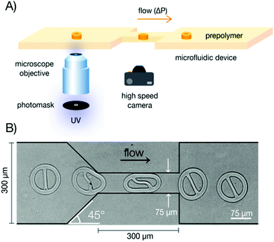
After particles were polymerized in the channel, flow of the prepolymer solution was started using applied pressure at the channel inlet (1 psi, unless otherwise specified), controlled by a Type 100 LR pressure regulator and a software-controlled 3-way solenoid valve (Type 6014, Burkert). High-speed videos were recorded (300–1000 fps, Phantom Miro M310, Vision Research) to capture particle passage through the narrow constriction of the channel (Fig. 1).
2.2 COMSOL model
COMSOL Multiphysics (version 4.4) finite element modeling software was used to simulate the deformation of the hydrogel particle within the microfluidic constriction. The system was modeled in the absence of fluid flow, since experiments showed negligible effect of viscous forces on steady-state particle shape for low applied pressures. The 3D structural mechanics model was comprised of a deformable particle (matching mask shapes used for experiments) sandwiched between two stiff rectangular bars. To deform the particle, the bars were set to displace from an initial position corresponding to the outer diameter of the undeformed particle (114 μm) to a final position corresponding to the dimensions of the microfluidic constriction (75 μm). Particle height was set to 17 μm (experimentally measured particle height). The ratio between the elastic moduli of the bars and the particle was set at 10![[thin space (1/6-em)]](https://www.rsc.org/images/entities/char_2009.gif) :
:![[thin space (1/6-em)]](https://www.rsc.org/images/entities/char_2009.gif) 1, based on literature values for PDMS43,44 and PEGDA hydrogel particles,45 although results were not affected when this ratio was increased up to 100
1, based on literature values for PDMS43,44 and PEGDA hydrogel particles,45 although results were not affected when this ratio was increased up to 100![[thin space (1/6-em)]](https://www.rsc.org/images/entities/char_2009.gif) :
:![[thin space (1/6-em)]](https://www.rsc.org/images/entities/char_2009.gif) 1 or decreased down to 2
1 or decreased down to 2![[thin space (1/6-em)]](https://www.rsc.org/images/entities/char_2009.gif) :
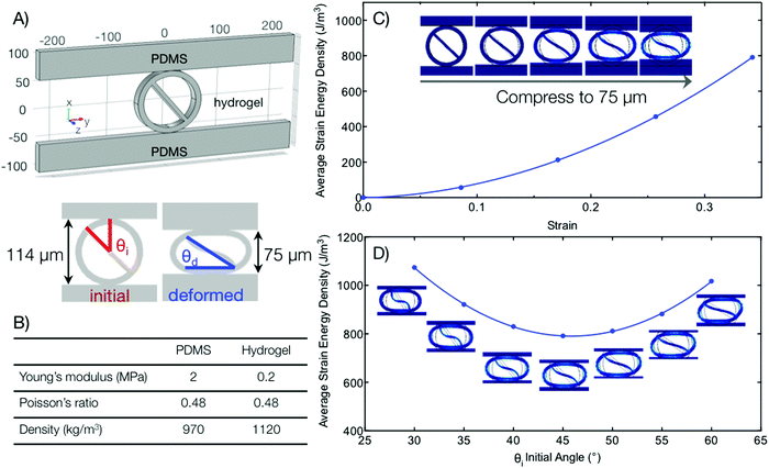
:![[thin space (1/6-em)]](https://www.rsc.org/images/entities/char_2009.gif) 1 by changing wall stiffness. Increasing the value of the elastic modulus of the hydrogel increased the average strain energy density in a linear manner. Both materials were assumed to be homogenous, isotropic, linear, and elastic, as well as nearly incompressible (Poisson's ratio set to 0.48).46,47 Model parameters are shown in Fig. 4A and B. A detailed workflow for the model is described in accompanying ESI.†
1 by changing wall stiffness. Increasing the value of the elastic modulus of the hydrogel increased the average strain energy density in a linear manner. Both materials were assumed to be homogenous, isotropic, linear, and elastic, as well as nearly incompressible (Poisson's ratio set to 0.48).46,47 Model parameters are shown in Fig. 4A and B. A detailed workflow for the model is described in accompanying ESI.†
For the initial condition of the model, we defined a small gap between the hydrogel particle and the PDMS bars to prevent the particle from being pinned to the bars at any point. Friction was imposed between the hydrogel and PDMS to keep the particle in place between the displacing bars during compression. The initial gap size, as well as the magnitude of the static friction coefficient did not significantly alter the simulation results, as long as the friction coefficient was sufficiently large to hold the particle in place (0.6% change in average energy density of deformed configuration for a change in static friction coefficient from 0.01 to 2). Thus, a static friction coefficient of 0.5 and a gap size of 0.01 μm were used for all simulations. The orientation of the particle was controlled in the model by setting the initial angle of rotation of the particle inside the horizontal bars. To determine the minimum energy configuration of different particle geometries, we plotted the average strain energy density of the deformed state as a function of initial angle for at least seven different angles, and fit the data with a quadratic equation (least squares method; R2 > 0.93 for all data sets).
3 Results and discussion
In this study, flow lithography provides a platform where microparticles of defined 2D-extruded shape can be fabricated directly in a microfluidic channel for subsequent interrogation of flow and deformation behaviour. During a typical experiment, a microfluidic channel containing a narrow constriction in the centre of the device (300 μm long, 75 μm wide) is filled with prepolymer solution. A particle with mask-defined shape is polymerized by UV light in the wide section of the channel (300 μm wide), with desired position and orientation relative to the entrance of the constriction (Fig. 1). A pressure difference (ΔP = 1 psi, unless otherwise specified) is applied across the device to drive the particle into the constriction, and the entrance and passage behaviour are captured using a high-speed camera. The rectangular microfluidic channel has a uniform height of 30 μm and a total length of 1 cm. The height of the polymerized particles is around 17 μm, due to an oxygen inhibition layer at the walls of the PDMS channel.48 This in situ method for particle fabrication and characterization is uniquely suitable for examining how microparticles of complex geometry flow through microfluidic channels.Fig. 1B shows the general shape of the simplest particle design: a ring supported by a single straight beam. During the course of this work, ring thickness and beam thickness are varied between 5–34 μm. The outer diameter of the particles is kept constant at 114 μm, and the external circular shape is maintained across all particle designs. In this way, we focus on the effect of varying internal structure – of both the beam (e.g. beam thickness, number of beams, beam placement) and the ring (e.g. non-uniform ring thicknesses) – on overall particle deformation. These hydrogel particles undergo elastic deformation in the microfluidic constriction, and fully recover their original shape upon exiting the constriction, as shown in Fig. 1B.
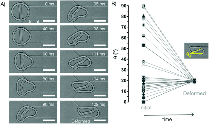
During entrance into the constriction, the ring-beam particles rotate to adopt a preferred configuration for entering the confined passageway, as shown in Fig. 2A. As soon as the entire particle has fully entered the constriction, this steady-state configuration is maintained for the duration of passage through the narrowed channel. Fig. 2A shows the typical entrance process for a particle with near vertical initial beam orientation (4°). We observe that the internal beam displays typical buckling behaviour as described by Euler's theory for slender columns subject to axial compression, where the buckled beam shape can be described by a sine wave.49 In biological cells, some microtubules – a component of the cytoskeletal network – will also buckle under compressive loading.50 In our experiments, at the 60–80 ms time points, the beam buckles similarly to a column with two fixed ends. However, as fluid flow enables rotation of the particle, the buckling behaviour switches to that of a column with one fixed end and one end free to translate laterally.49 Due to this extra degree of freedom, this second buckling configuration is more energetically favourable, and is the preferred steady-state shape.
As shown in Fig. 2B, the particle always adopts the same deformed configuration (or its mirror image), irrespective of initial orientation. The asymmetric internal structure of these particles – due to the presence of the beam – is responsible for their oriented transit. A similar phenomenon was shown in simulations of asymmetric multiple emulsion droplets, which displayed a preferred transit orientation during passage through an axisymmetric constriction.39 This suggests that the observations made using our pseudo-2D platform will also be relevant for three-dimensional shapes.
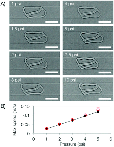
To determine the effect of fluid flow on the particle's steady-state configuration, we conducted the same experiment with ΔP ranging from 1–10 psi. Fig. 3A shows that the deformed shape of the particle does not show significant change up to 3 psi. At higher ΔP, viscous stresses begin to alter the shape of the particle. The linear relationship between pressure and maximum fluid speed in the narrow constriction is determined by a COMSOL model, and verified experimentally by tracking beads in prepolymer solution flowing through the device. The slight deviation between the measured flow speed and the COMSOL model at higher ΔP is likely due to PDMS deformation.46
Since the Reynolds number is small in our microfluidic system (<1 for the entire range of ΔP tested), inertial effects are negligible. Particle deformation is thus governed by the elastic forces of the particle as it resists geometric confinement, and by the viscous forces imposed on the particle from the surrounding fluid. The competing effect of viscous forces versus elastic forces can be described by an elastic capillary number.51,52 Viscous forces will depend on fluid viscosity and velocity, while elastic forces will depend on the elastic modulus of the hydrogel particle and a geometric parameter related to particle feature size (i.e. thickness of ring/beam), analogous to shell thickness for analysis of microcapsule deformation.52
By focusing on the low capillary number regime in this study, viscous forces become negligible and the steady-state particle shape is solely governed by particle elasticity under an imposed geometric strain. For our experiments, this corresponds to ΔP < 3 psi. In this regime, fluid forces affect the process dynamics but do not alter the steady-state configuration. All shape transformations between the initial and final state are scale-independent. Although we focus on the low capillary number regime in this work, it is interesting to note that at higher flow speeds, the particles adopt “bullet” shapes, with higher curvature at the front end. These types of shapes are characteristic of droplets and bubbles flowing through confined channels, and also observed in flow of capsules, vesicles, and red blood cells.22,23,53,54
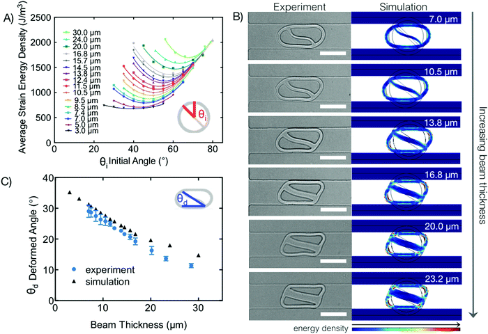
To confirm that the observed configuration of the deformed particles corresponds to a minimum energy state, we used COMSOL to build a simple finite element model for our system (Fig. 4). Since viscous forces are negligible, the model simply describes the elastic deformation of the particle due to geometric confinement. As shown in Fig. 4A–C, the 3D model depicts the compression of the particle between two stiff bars that displace to a final position corresponding to the width of the microfluidic constriction (75 μm). To determine the optimum steady-state configuration, the orientation of the particle is varied, and the average strain energy density of the fully compressed particle is plotted as a function of initial angle, as shown in Fig. 4D (0° initial angle represents a vertical beam, 90° represents horizontal). At small initial angles, compression of the particle results in large amplitude deformation of the buckled beam, and minimal deformation of the ring into an ellipsoid shape. The simulation fails at angles very close to 0° as friction is not enough to keep the particle between the compressing bars in such a high-energy configuration. At larger initial angles, compression of the particle results in less deformation of the beam, but more localized deformation of the ring as it transitions into a parallelogram shape. This leads to a minimum energy configuration that optimizes between beam deformation and ring deformation, which is determined by fitting a quadratic curve to the simulated data. For the particle shown in Fig. 4D, (10 μm thick ring with 7 μm thick beam), the optimal configuration corresponds to an initial angle around 45°.
To determine the optimal configuration of the particle, the entire structure must be considered as a whole. We cannot simply evaluate the most energetically favourable conformations of the beam and of the ring separately, but must take into account the constraints imposed by the joints between the beam and the ring. This is similar to the analysis used to determine the buckling of triangular frames.55,56 In our case, due to the thickness of both the ring and the beam, it is much easier to use a finite element simulation to determine the deformed state of the particle, compared to an analytical derivation.
Using our model, we examined the effect of beam thickness on the minimum energy deformation configuration of the hydrogel particles. Experiments were conducted by using different masks to fabricate particles with well-controlled beam thicknesses between 7 and 28 μm, and identical ring dimensions for all particles (inner diameter = 94 μm, outer diameter = 114 μm). We used the same polymerization conditions for all particles to ensure that the intrinsic material properties of the hydrogel did not change. For beam thicknesses less than 7 μm, configurations of the deformed particle were no longer consistent as we entered a higher elastic capillary number regime and fluid forces began to affect the beam configuration (Fig. S1A, ESI†). For beam thicknesses above 28 μm, we observed a different mode of deformation where the beam no longer deformed, and the ring compensated by taking on a dumbbell shape (Fig. S1B, ESI†).
We proceeded to use our COMSOL model to determine the minimum energy configurations of these particles with varying beam thicknesses (Fig. 5A). The strain energy curves become shallower for particles with thinner beams; this is expected since in the limiting case of a ring with no beam, the total strain energy of the particle no longer depends on initial orientation. As shown in Fig. 5B, there is excellent correlation between the observed steady-state shape in experiments, and the minimum energy configuration determined by simulation. In general, we observe that as beam thickness increases relative to ring thickness, the deformed particle shape transitions from an ellipse to a parallelogram, and the maximum length of the particle decreases. For a more quantitative comparison, we defined a “deformed angle” that measures the angle of the beam (centre to centre) from horizontal, in the deformed state. Fig. 5C shows a close match between experiment and simulation results, which both show that deformed angle decreases as beam thickness increases. As the beam increases in thickness, it becomes more resistant to deformation; as a result, we observe that the ring compensates by undergoing more local deformation to adopt a parallelogram shape. This corresponds to a smaller deformed angle (or larger initial angle). The small discrepancy between experiment and simulation shown in Fig. 5C is likely caused by experimental imperfections in particle shape – in experiments, the polymerized particles have beams that are slightly thinner in the middle of the particle compared to the ends, while the simulation particles have beams with uniform thickness (matching photomask shapes). Since the experimental beam thickness is measured in the middle of the particle, the measured value may be slightly less than the effective thickness of the beam. To test this hypothesis, we adjusted our simulation for several data points to account for the increased thickness of the beam at the connection points with the ring, and obtained a better match with experimental results (Fig. S2 and S2-1, ESI†).
We also tested particles with the same beam thickness to ring thickness ratio, but increasing thicknesses of both components (Fig. S3, ESI†). In this case, the overall particle shape is the same for all particles, confirming that shape is governed by the relative energy contributions (dictated by relative thickness) of the two components.
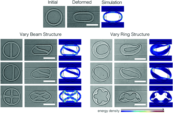
Guided by the observation that changing the particle beam to ring thickness ratio resulted in a transition in the overall particle shape, we examined the effects of alternate internal structures on the deformed particle shape (Fig. 6). We compared the deformed shapes of a ring, a ring with a single centred beam, a ring with a single off-centre beam and a ring with two crossing beams (beam thickness was kept constant at 13.8 μm). These variations resulted in distinct deformed shapes (ellipse, rounded parallelogram, asymmetric slipper-like, symmetric pointed-ellipse), which are related to the initial symmetry of the undeformed particles. Beam offset can be used to tune the final shape of the deformed particle, and control the contacting surface area between the particle and the sidewalls of the microfluidic constriction (Fig. S4, ESI†). We also compared particles with different ring structures and observed a rich variety of deformed shapes. Due to particle asymmetry, a non-uniform ring ensures particle reorientation to adopt a minimum energy configuration, similar to the addition of a beam to a uniform thickness ring. Our COMSOL model accurately predicts the steady-state configuration of all shape variations, showing the robustness of the model and experiment.
Other studies have used finite element simulations to model periodic structures that reversibly reconfigure into symmetric or chiral patterns due to elastic instabilities.10,56 These studies also showcase the scale-independent shape transformations of elastic materials and the ability to design structures with controlled deformation characteristics, which can be used to make auxetic materials. However, the macroscale experimental platform used for these studies (uniaxial compression of molded silicone lattices) is very different from our microfluidic platform. Using flow lithography, we are able to examine the elastic deformation of individual microparticles that can freely rotate to find their minimum energy state, in a biologically relevant flow environment. We can draw analogies of our system to red blood cells or leukocytes flowing through narrow capillaries – it is well known that these cells deform into a variety of shapes including symmetric parachutes and ellipsoids, and asymmetric slippers.11,53,57 Although the flow conditions and mechanical properties of our particles may differ from these cells, and we cannot account for active cytoskeletal reorganization, this study still raises interesting questions about how asymmetric internal structures can passively contribute to oriented transit of cells and the emergence of unique cell shapes in confined flow. It is already well known that the cytoskeleton plays an important role in breaking cell symmetry, which is necessary for important biological functions including cell division and migration.41
Knowledge of how particle structure affects shape changes during deformation can be applied in many different ways. As one example, we demonstrate how design of particle internal structure can be used to create particle “springs” – these particles contain an internal latch that locks when the particle deforms in a specific orientation (Fig. 7A). The particles remain locked upon exiting the constriction, storing elastic energy like loaded springs. The non-uniform ring structure ensures that the correct orientation is maintained during the latching process. The particles remain latched indefinitely within the wide region of the microfluidic channel. Fig. 7B shows a similar particle design with a uniform ring; in this case, the ring does not facilitate the correct orientation of the particle and latching is unsuccessful. The results shown in Fig. 7A and B are highly reproducible, as can be seen in Videos S1 and S2 (ESI†). After repeating the experiment twenty times, 20/20 of the particles shown in Fig. 7A successfully latch, while 0/20 of particles in Fig. 7B latch. Fig. 7C shows both types of particles downstream of the constriction.
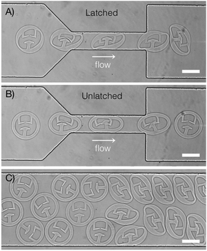 | ||
| Fig. 7 Using internal structure to design latching particle “springs”. (A) Particle with non-uniform outer ring maintains correct orientation to ensure latching. Image shows an overlay of frames from Video S1 (ESI†). (B) Particle with uniform outer ring does not latch. Image shows an overlay of frames from Video S2 (ESI†). (C) Image of both types of particle downstream of the constriction. Latching particles were synthesized first, followed by unlatched particles in the same channel. All latching particles remain latched in the wide section of the channel (N = 20). Scale bars are 75 μm. | ||
Latches can also be used to assemble multiple particles in chains or other complex structures.58–60 Existing techniques use railed microfluidic channels or complex valve-controlled chambers to ensure correct particle orientation during assembly. This requires particles to have specific external features, such as fins that can slot into railed channels,58,59 or patterned sides for alignment with other particles.60 We show how internal structure may be a more flexible method of maintaining correct orientation for intra- or inter-particle latching, which can be used for particles synthesized in situ or externally. To our knowledge, this is the first demonstration of using internal structure to engineer shape-changing particle “springs” based on elastic deformation in confined microfluidic channels.
4 Conclusions
We have shown that particle internal structure is responsible for controlling overall particle deformation in flow through microfluidic constrictions. Particles with different internal structures adopt a rich variety of deformed shapes. For low capillary numbers, these shapes correspond to minimum energy configurations due to particle reorientation at the entrance of the constriction.We also show that we can predict the optimal configurations of the deformed particles using a simple COMSOL model of linear elastic deformation. This model proves that fluid flow enables particle reorientation, but does not affect the final deformed shape of the particles in the small capillary number regime. For future work, we will explore the high capillary number regime and develop new models that incorporate the effect of viscous forces. We also plan to investigate interesting phenomena associated with passage dynamics of these structured microparticles. For example, when particles exit the constriction, they will briefly stretch due to an extensional flow field before restoring their original shape (Fig. 1B). Our preliminary observations show that for certain asymmetric particle shapes, this exit response can bias the trajectory of the particle from the centreline of the channel downstream of the constriction. The direction and amount of bias depends on the particle shape and its adopted configuration within the constriction.
By better understanding the role of internal structure on the passage and deformation of soft particles in confined geometries, we may be able to design reconfigurable particles with specific flow characteristics for diagnostic or therapeutic use. Further study using custom-shaped particles may also provide insight into how the cytoskeleton of biological cells passively contributes to cell deformation during transit through narrow passageways in vitro and in vivo.
Acknowledgements
This work was supported primarily by the MRSEC Program of the National Science Foundation under award number DMR - 1419807. L. C. was supported in part by a scholarship from Natural Sciences and Engineering Research Council (NSERC) of Canada. The authors thank Prof. Yeng-Long Chen and Wei-Ting Yeh for insightful discussions, Li-Chiun Cheng for viscosity measurements, and Doyle group members for helpful comments.References
- T. J. Merkel, S. W. Jones, K. P. Herlihy, F. R. Kersey, A. R. Shields, M. Napier, J. C. Luft, H. Wu, W. C. Zamboni, A. Z. Wang, J. E. Bear and J. M. DeSimone, Proc. Natl. Acad. Sci. U. S. A., 2011, 108, 586–591 CrossRef CAS PubMed.
- S. A. Bencherif, R. W. Sands, D. Bhatta, P. Arany, C. S. Verbeke, D. A. Edwards and D. J. Mooney, Proc. Natl. Acad. Sci. U. S. A., 2012, 109, 19590–19595 CrossRef CAS PubMed.
- C. Larson, B. Peele, S. Li, S. Robinson, M. Totaro, L. Beccai, B. Mazzolai and R. Shepherd, Science, 2016, 351, 1071–1074 CrossRef CAS PubMed.
- D. Rus and M. T. Tolley, Nature, 2015, 521, 467–475 CrossRef CAS PubMed.
- K. Bertoldi and M. Boyce, Phys. Rev. B: Condens. Matter Mater. Phys., 2008, 77, 052105 CrossRef.
- T. R. Hoare and D. S. Kohane, Polymer, 2008, 49, 1993–2007 CrossRef CAS.
- J. P. Best, Y. Yan and F. Caruso, Adv. Healthcare Mater., 2012, 1, 35–47 CrossRef CAS PubMed.
- B. V. Slaughter, S. S. Khurshid, O. Z. Fisher, A. Khademhosseini and N. A. Peppas, Adv. Mater., 2009, 21, 3307–3329 CrossRef CAS PubMed.
- J. Kim, J. A. Hanna, M. Byun, C. D. Santangelo and R. C. Hayward, Science, 2012, 335, 1201–1205 CrossRef CAS PubMed.
- J. Shim, S. Shan, A. Košmrlj, S. H. Kang, E. R. Chen, J. C. Weaver and K. Bertoldi, Soft Matter, 2013, 9, 8198–8202 RSC.
- S. Guido and G. Tomaiuolo, C. R. Phys., 2009, 10, 751–763 CrossRef CAS.
- A. C. Rowat, D. E. Jaalouk, M. Zwerger, W. L. Ung, I. A. Eydelnant, D. E. Olins, A. L. Olins, H. Herrmann, D. A. Weitz and J. Lammerding, J. Biol. Chem., 2013, 288, 8610–8618 CrossRef CAS PubMed.
- S. Kumar and V. M. Weaver, Cancer Metastasis Rev., 2009, 28, 113–127 CrossRef PubMed.
- H. M. Wyss, T. Franke, E. Mele and D. A. Weitz, Soft Matter, 2010, 6, 4550 RSC.
- C. Duprat, H. Berthet, J. S. Wexler, O. du Roure and A. Lindner, Lab Chip, 2015, 15, 244–252 RSC.
- H. Bow, I. V. Pivkin, M. Diez-Silva, S. J. Goldfless, M. Dao, J. C. Niles, S. Suresh and J. Han, Lab Chip, 2011, 11, 1065–1073 RSC.
- W. Zhang, K. Kai, D. S. Choi, T. Iwamoto, Y. H. Nguyen, H. Wong, M. D. Landis, N. T. Ueno, J. Chang and L. Qin, Proc. Natl. Acad. Sci. U. S. A., 2012, 109, 18707–18712 CrossRef CAS PubMed.
- A. C. Anselmo, M. Zhang, S. Kumar, D. R. Vogus, S. Menegatti, M. E. Helgeson and S. Mitragotri, ACS Nano, 2015, 9, 3169–3177 CrossRef CAS PubMed.
- F. P. Bretherton, J. Fluid Mech., 1961, 10, 166–188 CrossRef.
- C. N. Baroud, F. Gallaire and R. Dangla, Lab Chip, 2010, 10, 2032–2045 RSC.
- H. Sun, M. Björnmalm, J. Cui, E. H. H. Wong, Y. Dai, Q. Dai, G. G. Qiao and F. Caruso, ACS Macro Lett., 2015, 4, 1205–1209 CrossRef CAS.
- S.-Y. Park and P. Dimitrakopoulos, Soft Matter, 2013, 9, 8844–8855 RSC.
- G. Coupier, A. Farutin, C. Minetti, T. Podgorski and C. Misbah, Phys. Rev. Lett., 2012, 108, 178106 CrossRef PubMed.
- T. Savin, M. M. Bandi and L. Mahadevan, Soft Matter, 2015, 12, 562–573 RSC.
- Y. Li, E. Kumacheva and A. Ramachandran, Soft Matter, 2013, 9, 10391 RSC.
- J. Cui, M. Björnmalm, K. Liang, C. Xu, J. P. Best, X. Zhang and F. Caruso, Adv. Mater., 2014, 26, 7295–7299 CrossRef CAS PubMed.
- D. Dendukuri, D. C. Pregibon, J. Collins, T. A. Hatton and P. S. Doyle, Nat. Mater., 2006, 5, 365–369 CrossRef CAS PubMed.
- R. Haghgooie, M. Toner and P. S. Doyle, Macromol. Rapid Commun., 2010, 31, 128–134 CAS.
- A. Lindner and M. Shelley, in Fluid-structure interactions at low Reynolds numbers, Royal Society of Chemistry, 4th edn, 2016, pp. 168–192 Search PubMed.
- A. Lindner, Phys. Fluids, 2014, 26, 101307 Search PubMed.
- M. J. Solomon, Curr. Opin. Colloid Interface Sci., 2011, 16, 158–167 CrossRef CAS.
- S. Sacanna, D. J. Pine and G.-R. Yi, Soft Matter, 2013, 9, 8096 RSC.
- S. Mitragotri and J. Lahann, Nat. Mater., 2009, 8, 15–23 CrossRef CAS PubMed.
- M. Masaeli, E. Sollier, H. Amini, W. Mao, K. Camacho, N. Doshi, S. Mitragotri, A. Alexeev and D. Di Carlo, Phys. Rev. X, 2012, 2, 031017 Search PubMed.
- W. E. Uspal, H. Burak Eral and P. S. Doyle, Nat. Commun., 2013, 4, 2666 Search PubMed.
- J. A. Champion and S. Mitragotri, Proc. Natl. Acad. Sci. U. S. A., 2006, 103, 4930–4934 CrossRef CAS PubMed.
- S. Barua, J. Yoo, P. Kolhar, A. Wakankar, Y. R. Gokarn and S. Mitragotri, Proc. Natl. Acad. Sci. U. S. A., 2013, 110, 3270–3275 CrossRef CAS PubMed.
- M. Caggioni, A. V. Bayles, J. Lenis, E. M. Furst and P. T. Spicer, Soft Matter, 2014, 10, 7647–7652 RSC.
- J. Wang, X. Li, X. Wang and J. Guan, Phys. Rev. E: Stat., Nonlinear, Soft Matter Phys., 2014, 89, 052302 CrossRef PubMed.
- O. Lieleg, M. M. A. E. Claessens and A. R. Bausch, Soft Matter, 2010, 6, 218 RSC.
- R. D. Mullins, Cold Spring Harbor Perspect. Biol., 2010, 2, 1–16 Search PubMed.
- D. Dendukuri, S. S. Gu, D. C. Pregibon, T. A. Hatton and P. S. Doyle, Lab Chip, 2007, 7, 818–828 RSC.
- J. C. Lötters, W. Olthuis, P. H. Veltink and P. Bergveld, J. Micromech. Microeng., 1999, 7, 145–147 CrossRef.
- X. Q. Brown, K. Ookawa and J. Y. Wong, Biomaterials, 2005, 26, 3123–3129 CrossRef CAS PubMed.
- J. J. Kim, K. W. Bong, E. Reátegui, D. Irimia and P. S. Doyle, Nat. Mater., 2017, 16, 139–146 CrossRef CAS PubMed.
- T. Gervais, J. El-Ali, A. Günther and K. F. Jensen, Lab Chip, 2006, 6, 500–507 RSC.
- D. L. Elbert and J. A. Hubbell, Biomacromolecules, 2001, 2, 430–441 CrossRef CAS PubMed.
- D. Dendukuri, P. Panda, R. Haghgooie, J. M. Kim, T. A. Hatton and P. S. Doyle, Macromolecules, 2008, 41, 8547–8556 CrossRef CAS.
- S. P. Timoshenko and J. M. Gere, Theory of Elastic Stability, McGraw-Hill Book Company, Inc., 2nd edn, 1961 Search PubMed.
- N. Wang, K. Naruse, D. Stamenović, J. J. Fredberg, S. M. Mijailovich, I. M. Tolić-Nørrelykke, T. Polte, R. Mannix and D. E. Ingber, Proc. Natl. Acad. Sci. U. S. A., 2001, 98, 7765–7770 CrossRef CAS PubMed.
- D. Barthès-Biesel, Annu. Rev. Fluid Mech., 2016, 48, 25–52 CrossRef.
- G. Zhu, A. Alexeev and A. C. Balazs, Macromolecules, 2007, 40, 5176–5181 CrossRef CAS.
- M. Abkarian, M. Faivre, R. Horton, K. Smistrup, C. A. Best-Popescu and H. A. Stone, Biomed. Mater., 2008, 3, 034011 CrossRef PubMed.
- M. J. Martinez and K. S. Udell, J. Fluid Mech., 1990, 210, 565–591 CrossRef CAS.
- M. Gregory, Elastic Instablity: Analysis of Buckling Modes and Loads of Framed Structures, E. & F. N. Spon Ltd, London, 1967 Search PubMed.
- S. H. Kang, S. Shan, A. Košmrlj, W. L. Noorduin, S. Shian, J. C. Weaver, D. R. Clarke and K. Bertoldi, Phys. Rev. Lett., 2014, 112, 098701 CrossRef PubMed.
- D. M. Redenbach, D. English and J. C. Hogg, Am. J. Physiol., 1997, 273, L733–L740 CAS.
- S. E. Chung, W. Park, S. Shin, S. A. Lee and S. Kwon, Nat. Mater., 2008, 7, 581–587 CrossRef CAS PubMed.
- W. Park, H. Lee, H. Park and S. Kwon, Lab Chip, 2009, 9, 2169–2175 RSC.
- M. T. Tolley, M. Krishnan, D. Erickson and H. Lipson, Appl. Phys. Lett., 2008, 93, 254105 CrossRef.
Footnote |
| † Electronic supplementary information (ESI) available. See DOI: 10.1039/c6sm02674e |
| This journal is © The Royal Society of Chemistry 2017 |

