
Homoleptic thiazole-based IrIII phosphorescent complexes for achieving both high EL efficiencies and an optimized trade-off among the key parameters of solution-processed WOLEDs†
Haoran
Guo
a,
Jiang
Zhao
a,
Zhuanzhuan
Tian
a,
Yong
Wu
a,
Boao
Liu
a,
Feifan
Dang
a,
Xiaolong
Yang
a,
Guijiang
Zhou
*a,
Zhaoxin
Wu
*b and
Wai-Yeung
Wong
*cd
aMOE Key Laboratory for Nonequilibrium Synthesis and Modulation of Condensed Matter, Institute of Chemistry for New Energy Material, Department of Chemistry, School of Science, State Key Laboratory for Mechanical Behavior of Materials, Xi’an Jiaotong University, Xi’an 710049, P. R. China. E-mail: zhougj@mail.xjtu.edu.cn; Fax: +86-29-8266-3914
bKey Laboratory for Physical Electronics and Devices of the Ministry of Education, Faculty of Electronic and Information Engineering, Xi’an Jiaotong University, Xi’an 710049, P. R. China. E-mail: zhaoxinwu@mail.xjtu.edu.cn
cInstitute of Molecular Functional Materials and Department of Chemistry, Hong Kong Baptist University, Waterloo Road, Kowloon Tong, Hong Kong, P. R. China. E-mail: rwywong@hkbu.edu.hk
dDepartment of Applied Biology and Chemical Technology, The Hong Kong Polytechnic University, Hung Hom, Hong Kong, P. R. China. E-mail: wai-yeung.wong@polyu.edu.hk
First published on 21st November 2016
Abstract
Two homoleptic thiazole-based IrIII phosphorescent emitters, Ir-3Tz1F and Ir-3Tz2F, with fluorinated 2-phenylthiazole-type ligands were designed and prepared. Their thermal stability, and photophysical and electrochemical properties, as well as electroluminescent (EL) performances in both monochromic OLEDs and solution-processed WOLEDs were investigated. When doped in monochromic OLEDs made by vacuum deposition, Ir-3Tz1F gave the maximum EL efficiencies with ηL of 56.2 cd A−1, ηext of 15.8% and ηp of 50.2 lm W−1. Critically, solution-processed WOLEDs based on Ir-3Tz1F with three primary colors could achieve an excellent trade-off among the stable balanced white EL spectra, a high EL efficiency and a high color rendering index (CRI). The optimized solution-processed WOLED exhibited very attractive EL efficiencies of 33.4 cd A−1, 16.5% and 30.6 lm W−1, while maintaining both a high CRI of ca. 80 and very stable Commission Internationale de L’Eclairage (CIE) coordinates in a wide driving voltage range from 4 V to 11 V.
Introduction
Regarded as a hybrid of an electron-deficient pyridyl moiety and an electron-rich thiophenyl ring,1 the thiazolyl group can afford distinct electronic features to tune the photophysical properties of phosphorescent IrIII/PtII 2-phenylpyridine (ppy)-type complexes bearing thiazole-based ligands, since the emission color, the phosphorescent quantum yield (ΦP), the phosphorescent lifetime (τP) and the charge carrier injection/transporting properties of these phosphorescent (triplet) complexes can be greatly affected by the electronic structures of the chelated organic ligands.2–10 All of these photophysical properties can play a critical role in optimizing the electroluminescent (EL) performances of the concerned phosphorescent (triplet) complexes in organic light-emitting diodes (OLEDs), which then show great potential in the development of both new-generation flat panel displays and future energy-saving lighting sources.11–15 More commonly, it is the benzothiazole rather than thiazole group that has been employed to construct the ligands of phosphorescent IrIII/PtII ppy-type complexes.3,16 Quite a number of benzothiazole-based IrIII ppy-type triplet emitters have been developed that show high EL efficiencies.17–22 Furthermore, some functional groups, such as carbazole,21 dibenzothiophene-S,S-dioxide18 and the triphenylphosphoryl unit,18 have been introduced to furnish carrier injection/transporting capabilities to the concerned benzothiazole-based IrIII ppy-type triplet emitters to optimize their EL performances.Recently, the thiazole group has been introduced to ppy-type ligands to develop thiazole-based phosphorescent IrIII/PtII emitters.23–26 We have prepared ppy-type triplet emitters with either 2-naphthylthiazole-type23 or 2-phenylthiazole-type25 ligands. It was shown that the phosphorescence color of the complexes can be tuned by the substitution position of the thiazole unit on the naphthalene23 and the fluorine group attached to the ligands.25 Furthermore, the substitution position of the thiazole unit can also exert a great influence on the EL efficiencies of the naphthylthiazole-type phosphorescent IrIII/PtII emitters.23 In addition, the functional groups, such as triphenylamine (TPA)24 and carbazole,26 have also been combined with thiazole to prepare novel thiazole-based ligands, which have been chelated with an IrIII center to develop functionalized phosphorescent emitters with attractive EL performances. All of these results indicate a great potential for thiazole-based phosphorescent emitters in the field of OLEDs. Unfortunately, they are relatively rare and generally have a heteroleptic configuration.
Due to the inherent electronic features associated with the thiazole unit, thiazole-based phosphorescent IrIII emitters typically exhibit a bathochromic effect in the phosphorescent wavelength with respect to that of their pyridine-based analogues.24,26 Therefore, they generally emit orange/yellow phosphorescence, which can be coupled with blue emission to construct white organic light-emitting diodes (WOLEDs) of complementary colors.24 Thiazole-based phosphorescent IrIII emitters bearing a TPA functional group have been applied to complementary colored WOLEDs, which have shown decent EL efficiencies.24 However, the white EL spectra for the concerned WOLEDs vary markedly under different driving voltages, leading to a great variation in both the Commission Internationale de L’Eclairage (CIE) coordinates and the color rendering index (CRI).24 Some WOLEDs with a single emission layer also show voltage-dependent white EL spectra.27,28 In addition, there is a trade-off issue between the luminous efficiency and the color quality for white emission from WOLEDs. This means that the trichromatic WOLEDs with red, green and blue (R–G–B) emitters typically have a better color quality, but lower EL efficiency.15 All these issues are really undesirable for the practical application of WOLEDs as new energy-saving lighting sources. Therefore it is necessary to develop new thiazole-based phosphorescent emitters with diverse properties and structures to cope with the critical problems in the field of OLEDs, particularly those associated with WOLEDs. Therefore, in the present study, two homoleptic phosphorescent thiazole-based ppy-type IrIII emitters were developed to furnish not only high efficiency monochromic OLEDs, but also address the optimized trade-off in solution-processed WOLEDs with a single doped emission layer.
Experimental
Spectroscopy
UV/Vis spectra were recorded with a Shimadzu UV-2250 spectrophotometer. The steady-state photoluminescent (PL) properties of the complexes were measured with Edinburgh FLS920 fluorometers. The phosphorescence quantum yields (ΦP) were determined in degassed CH2Cl2 solution at 298 K against the fac-[Ir(ppy)3] standard (ΦP = 0.40).29 The lifetimes were measured with a single photon counting spectrometer from Edinburgh Instruments (FLS-920) with a picosecond pulse LED excitation source. The data analysis was conducted by iterative convolution of the luminescence decay profile with the instrument response function using the software package provided by Edinburgh Instruments. DSC was performed with a NETZSCH DSC 200 PC unit under a nitrogen flow at a heating rate of 10 °C min−1. TGA was conducted with a NETZSCH STA 409C instrument under nitrogen with a heating rate of 20 °C min−1. Fast atom bombardment (FAB) mass spectra were recorded with a Finnigan MAT SSQ710 system. 1H, 13C and 19F NMR spectra were recorded on a Bruker Avance 400 MHz spectrometer.Cyclic voltammetry studies
Electrochemical measurements were performed using a Princeton Applied Research 2273A potentiostat. Cyclic voltammetry (CV) of the sample solutions was performed at a scan rate of 100 mV s−1 using a glassy carbon working electrode, a platinum counter electrode, and a platinum-wire reference electrode. The solvent was deoxygenated acetonitrile, and the supporting electrolyte was 0.1 M [nBu4N][BF4]. Ferrocene (Fc) was added as a calibrant after each set of measurements, and all the potentials reported are quoted with reference to the ferrocene/ferrocenium (Fc/Fc+) couple. The HOMO energy level was obtained using the following equation: EHOMO = −(Ea + 4.8) eV.30 However, the LUMO energy level was determined from ELUMO = (Eg + EHOMO) eV (Eg: optical band gap derived from the absorption onset in the UV/Vis spectra).Synthesis
All the reactions were conducted under a nitrogen atmosphere and no special precautions were required during workup. The solvents were carefully dried and distilled from appropriate drying agents prior to use. Commercially available reagents were used without further purification unless otherwise stated. All the reactions were monitored by TLC with Merck pre-coated aluminum plates. Flash column chromatography was carried out using silica gel (200–300 mesh). [Ir(acac)3], organic boric acid and 2-bromothiazole were purchased from Sigma-Aldrich. The organic ligands L1 and L2 were prepared following our published strategy.25 The red phosphorescent emitter Ir-G1 was obtained from our laboratory and the details of its preparation were provided in our previous report.31Typical procedure for synthesizing the complexes Ir-3Tz1F and Ir-3Tz2F
Under an N2 atmosphere, the corresponding organic ligand (3.5 equiv.) and [Ir(acac)3] (1.0 equiv.) were added to glycerol. The resulting mixture was stirred at ca. 220 °C for 10 h. After completion of the reaction, 1.0 M aqueous hydrochloric acid was added to the solution, resulting in precipitation of the colored crude product, which was filtered, washed with water and dried at 100 °C under vacuum. The purification of the product was carried out using silica-gel column chromatography eluting with CH2Cl2/hexane (2![[thin space (1/6-em)]](https://www.rsc.org/images/entities/char_2009.gif) :1, v/v). The concerned complex was obtained as a yellow solid.
:1, v/v). The concerned complex was obtained as a yellow solid.
OLED fabrication and measurements
The pre-cleaned ITO glass substrates were treated with ozone for 20 min. A thin MoO3 layer was deposited on the surface of the ITO glass to form a 4 nm-thick hole-injection layer. Then, a 50 nm-thick layer of CBP with a 15 nm local doping zone was constructed to serve as both the hole-transporting and emission layers. After that, TPBi (40 nm), LiF (1 nm) and the Al cathode (100 nm) were successively evaporated. For the fabrication of the WOLEDs, PEDOT:PSS was first deposited on the treated ITO glass by applying a spin-coating strategy. Then, the ITO-coated glass was dried at ca. 100 °C for 1 h. The chloroform solution containing the host materials and emitters was spin-coated with a concentration of ca. 10 mg mL−1. After drying at ca. 50 °C for 0.5 h, other functional layers of TPBi (40 nm), LiF (1 nm) and the Al cathode (100 nm) were successively evaporated. All the evaporation processes were conducted at a base pressure of less than 10−6 Torr. The EL spectra and CIE coordinates were measured with a PR650 spectra colorimeter. The J–V–L curves of the devices were recorded by a Keithley 2400/2000 source meter and the luminance was measured using a PR650 SpectraScan spectrometer. All the experiments and measurements were carried out under ambient conditions.Computational details
Density functional theory (DFT) calculations using the B3LYP functional were performed for all the IrIII complexes and their geometries were obtained by theoretical optimization during the computation. The basis set used for the C, H, F, N and O atoms was 6-31G, whereas effective core potentials with a LanL2DZ basis set were employed for the S and Ir atoms.32,33 The energies of the excited states of the complexes were computed by time-dependent (TD) DFT (TD-DFT) based on all the ground-state geometries. All the calculations were carried out using the Gaussian 09 program.34 Mulliken population analyses were performed using MullPop.35 Frontier molecular orbitals obtained from the DFT calculations were plotted using the Molden 3.7 program.36Results and discussion
Synthesis and characterization
The synthetic procedure for the thiazole-based homoleptic IrIII ppy-type phosphorescent emitters is shown in Scheme 1. In order to prepare the complexes, the organic ligands L1 and L2 should be synthesized first via a Suzuki cross-coupling reaction between 2-bromothiazole and the corresponding fluorinated phenyl boronic acid with Pd(PPh3)4 as the catalyst. With the aim to tune the maximum phosphorescent wavelength of the complexes, a fluorine substituent was introduced to the organic ligands. All the ligands could be easily obtained in good yields over 80%. After obtaining the organic ligands, the two homoleptic phosphorescent IrIII complexes were prepared according to the well-established one-pot strategy by the cyclometalation of [Ir(acac)3] (acac: acetylacetone anion) with the corresponding organic ligands in glycerol at ca. 220 °C.4,23,24 The homoleptic IrIII complexes were purified by silica-gel chromatography in high purity as air-stable yellow powders. | ||
| Scheme 1 Synthetic sketches for the thiazole-based phosphorescent IrIII complexes Ir-3Tz1F and Ir-3Tz2F. | ||
In the 1H NMR spectra of the two homoleptic IrIII complexes, only one set of signals assigned to the protons of the three thiazole-based ligands, corresponding to the fac-isomers, were obtained for both Ir-3Tz1F and Ir-3Tz2F. In the 19F NMR spectrum of Ir-3Tz1F, the single resonance peak at ca. −110.36 ppm indicates the only –F group on the chelated phenyl ring of the thiazole-based ligand. For Ir-3Tz2F, the two sets of double resonance peaks at ca. −106.50 ppm and −108.91 ppm in its 19F NMR spectrum are consistent with the fluoro-substitution pattern of its ligand as well.
Thermal and photophysical properties
The thermal properties of the thiazole-based phosphorescent IrIII complexes were characterized by both thermogravimetric analysis (TGA) and differential scanning calorimetry (DSC) under a nitrogen flow. The TGA results show that an evident decomposition process occurs at ca. 380 °C for Ir-3Tz1F and 365 °C for Ir-3Tz2F (Table 1 and Fig. S1a in the ESI†), which are much higher than their heteroleptic counterparts.25 However, it seems that a slight decomposition of Ir-3Tz2F begins at ca. 160 °C (Fig. S1a, ESI†), indicating its poorer stability with respect to that of Ir-3Tz1F. This might be ascribed to the higher molecular activity of Ir-3Tz2F induced by the multiple highly polar C–F bonds.37 The DSC traces for the homoleptic thiazole-based IrIII complexes indicate high glass-transition temperatures (Tg) of ca. 215 °C for Ir-3Tz1F (Table 1 and Fig. S1b, ESI†). However, it appears that Ir-3Tz2F exhibits one exothermic process at ca. 165 °C and an endothermic process at ca. 220 °C (Fig. S1b, ESI†). With respect to the TGA curve for Ir-3Tz2F (Fig. S1a, ESI†), the former exothermic process should be induced by the slight decomposition of Ir-3Tz2F. Similar to that of Ir-3Tz1F, the glass-transition event occurring at ca. 220 °C for Ir-3Tz2F can be related to the distortion of the entire rigid molecular skeleton.| Complexes |
Absorption
298 K |
Emission
298 K |
Φ P | τ P (μs) | T d /T g (°C) |
|---|---|---|---|---|---|
|
a Measured in CH2Cl2 at a concentration of 10−5 M, with logε values shown in parentheses.
b Measured in CH2Cl2 at a concentration of 10−5 M.
c In degassed CH2Cl2 relative to fac-[Ir(ppy)3] (ΦP = 0.40), λex = 360 nm.
d Measured in degassed CH2Cl2 solutions at a sample concentration of ca. 10−5 M; the excitation wavelength was set at 355 nm for all the samples at 298 K.
|
|||||
| Ir-3Tz1F | 249 (4.67), 281 (4.67), 303 (4.57), 364 (4.14), 402 (3.92), 434 (3.83) | 525, 555 | 0.29 | 0.73 (525 nm), 1.61 (555 nm) | 380/215 |
| Ir-3Tz2F | 270 (4.71), 283 (4.66), 295 (4.59), 343 (4.20), 382 (4.01), 418 (3.51) | 508, 533 | 0.28 | 1.20 (507 nm), 1.33 (533 nm) | 365/220 |
Both of the homoleptic thiazole-based IrIII complexes show two distinct absorption bands in their UV-Vis spectra (Fig. 1 and Table 1). The high-energy strong UV absorption bands before 310 nm should be induced by the spin-allowed S1 ← S0 transitions of the organic ligands. On the contrary, the weaker and low-energy absorption located beyond 310 nm can be assigned to the charge transfer (CT) transitions in both singlet and triplet states. Clearly, the energy levels for the CT absorption bands fall in the order of Ir-3Tz1F < Ir-3Tz2F (Fig. 1).
 | ||
| Fig. 1 UV-vis and photoluminescence (PL) spectra for the homoleptic thiazole-based phosphorescent IrIII complexes. | ||
Upon UV light irradiation at 360 nm, both the homoleptic thiazole-based IrIII complexes emit strong phosphorescence in CH2Cl2 (Fig. 1 and Table 1). Their photoluminescence (PL) spectra display a double-peak pattern (Fig. 1). Clearly, the high-energy phosphorescent emission bands (ca. 529 nm for Ir-3Tz1F and 507 nm for Ir-3Tz2F) exhibit an unstructured line shape, whereas the low-energy ones (ca. 555 nm for Ir-3Tz1F and 533 nm for Ir-3Tz2F) show a well-structured line shape (Fig. 1 and Table 1). The triplet/phosphorescent character of these emission bands was supported by the long lifetime in the order of microseconds for the associated excited states.
In order to interpret the aforementioned photophysical results of these homoleptic thiazole-based phosphorescent IrIII complexes, DFT calculations were carried out and the results are shown in Fig. 2 and Table 2. The DFT calculation results indicate that the lowest-energy transitions correspond to HOMO → LUMO (H → L) transitions with non-zero oscillator strengths for the S1 states of the two homoleptic thiazole-based IrIII complexes. However, the transitions HOMO → LUMO (H → L), HOMO → LUMO+1 (H → L+1), HOMO−2 → LUMO (H−2 → L) and HOMO−2 → LUMO+1 (H−2 → L+1) represent features of their T1 states (Table 2), which are responsible for the phosphorescence in the two homoleptic thiazole-based IrIII complexes. As indicated by the noticeably different contribution to the HOMO/HOMO−2 and LUMO/LUMO+1 from the metal dπ orbitals (Table 2 and Fig. 2), the lowest-energy excited states, S1 and T1, show evident metal-to-ligand charge transfer (MLCT) features. In addition, the intra-ligand charge transfer (ILCT) features from the phenyl ring to the thiazole unit can also be seen according to the distribution patterns of the critical transitions corresponding to the characters of the lowest-energy excited states S1 and T1 (Fig. 2). Hence, it can be concluded that the S1 and T1 states associated with the two homoleptic thiazole-based IrIII complexes should consist of mixed MLCT and ILCT states. Therefore, the weak CT absorption bands in the UV-Vis spectra of Ir-3Tz1F and Ir-3Tz2F are induced by singlet and triplet MLCT states (1MLCT and 3MLCT) as well as those of ILCT states (1ILCT and 3ILCT).
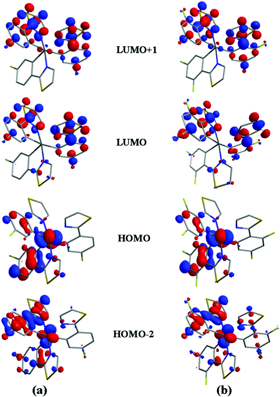 | ||
| Fig. 2 Key frontier molecular orbitals corresponding to the important transition processes in (a) Ir-3Tz1F and (b) Ir-3Tz2F. | ||
| Compound | Contribution of metal dπ orbitalsa | Contribution of metal dπ orbitalsa | Largest coefficient in the CI expansion of the T1 state (S0 → T1 excitation energy)b | Largest coefficient in the CI expansion of the S1 state (S0 → S1 excitation energy)b | Oscillator strength (f) of the S0 → S1 transition |
|---|---|---|---|---|---|
| a Data were obtained by exporting DFT results with the software AOMix. b H → L represents the HOMO to LUMO transition. CI stands for configuration interaction. | |||||
| Ir-3Tz1F |
HOMO−2: 21.3%
HOMO: 37.1% |
LUMO+1: 3.4%
LUMO: 1.5% |
H → L: 0.34777
24.2% H → L+1: 0.22311 10.0% H−2 → L: 0.25445 12.9% H−2 → L+1: 0.25584 13.1% (489 nm) |
H → L: 0.67760
91.8% H → L+1: 0.15807 5.0% (402 nm) |
0.0407 |
| Ir-3Tz2F |
HOMO−2: 23.9%
HOMO: 38.1% |
LUMO+1: 3.6%
LUMO: 1.6% |
H → L: 0.30468
18.6% H → L+1: −0.21271 9.05% H−2 → L: 0.30397 18.5% H−2 → L+1: −0.27530 15.2% (470 nm) |
H → L: 0.66742
89.1% H → L+1: −0.18832, 7.1% (381 nm) |
0.0420 |
Owing to the large contribution from the metal dπ orbitals to both the HOMO and HOMO−2 of the homoleptic thiazole-based IrIII complexes (Fig. 2 and Table 2), the molecular orbitals (MO) of the organic ligands and the metal center are mixed effectively to induce strong spin–orbit coupling effects. Therefore, triplet absorption bands occur with the feature of both 3MLCT and 3ILCT and induce the phosphorescent emission at 298 K (Fig. 1). According to the established relationship between the T1 character and line shape of the phosphorescent spectra for the IrIII complexes,3,4 the high-energy broad and featureless phosphorescent band of the homoleptic thiazole-based IrIII complexes can be assigned to the radiative decay of the 3MLCT states, whereas the low-energy sharp phosphorescent band should come from the emissive decay of the ligand-centered 3ILCT states (Fig. 1) due to its vibronic fine structure observed at a low temperature of 77 K (Fig. S1c, ESI†). Owing to the close energy levels for the 3MLCT and 3ILCT states (Fig. 1), there should be a competition between their radiative decay processes. Therefore, Ir-3Tz1F and Ir-3Tz2F exhibit dual emission bands (Fig. 1), as typically observed in ppy-type IrIII phosphorescent complexes.3,4 Similar to those of their analogues in the literature,23,24 HOMO and HOMO−2 for both Ir-3Tz1F and Ir-3Tz2F are mainly located on the dπ orbitals of the IrIII center and on the π orbitals of the phenyl rings. Hence, introducing a strongly electron-withdrawing –F group to the phenyl ring will stabilize the HOMO and HOMO−2 and lower their energy levels, which should increase the energy associated with the transitions corresponding to the T1 states and elevate their energy levels. Hence, Ir-3Tz1F should possess T1 states with lower energy levels to induce phosphorescence with a longer wavelength with respect to that of Ir-3Tz2F, which was shown by the PL spectra of the homoleptic thiazole-based IrIII complexes (Fig. 1 and Table 1). Hence, there is good consistency between the experimental results and the theoretical calculations.
Electrochemical characterization
The electrochemical properties of the two homoleptic thiazole-based IrIII complexes were investigated by cyclic voltammetry (CV) calibrated with ferrocene as the internal standard under a nitrogen atmosphere. Both of the complexes showed a reversible oxidation couple (Ea) at ca. 0.61 V for Ir-3Tz1F and 0.72 V for Ir-3Tz2F (Table 3). With two –F groups on the phenyl ring of the ligand, the oxidation potential of Ir-3Tz2F moves markedly to a more positive region due to the stabilization effect on the HOMOs induced by the –F groups (vide infra). The reduction potentials (Ec) for the two complexes are located at ca. −2.56 V for Ir-3Tz1F and −2.14 V for Ir-3Tz2F (Table 3). From the MO patterns of the thiazole-based IrIII complexes, it could be seen clearly that the phenyl rings of the organic ligands also make a large contribution to their LUMOs (Fig. 2). As a result, introducing more –F groups with a strong electron-withdrawing ability to the phenyl rings of the organic ligands should lower the LUMO levels of the thiazole-based IrIII complexes and make them easier to be reduced. Therefore, Ir-3Tz2F possesses Ec at a less negative potential region with respect to Ir-3Tz1F (Table 3). The irreversibility of the reduction process of the complexes can be ascribed to their character being more susceptible to other environmental factors. The irreversible reduction processes of the two complexes during the cathodic sweep make their LUMO levels poorly reliable, as seen based on electrochemistry measurements. Therefore, we calculated their LUMO levels from the optical gap (Eg).| Compound | E a (V) | E c (V) | HOMOc (eV) | LUMOd (eV) |
|---|---|---|---|---|
| a Reversible; the value was set as E1/2. b Irreversible; the value was derived from the cathodic peak potential. c HOMO levels were calculated according to the equation HOMO = −(4.8 + Ea). d LUMO levels were obtained from the optical gap Eg. | ||||
| Ir-3Tz1F | 0.61a | −2.56b | −5.41 | −3.01 |
| Ir-3Tz2F | 0.72a | −2.14b | −5.52 | −3.43 |
Electrophosphorescent characterization
The electrophosphorescent properties of Ir-3Tz1F and Ir-3Tz2F were characterized by phosphorescent OLEDs (PhOLEDs) with the configuration of ITO/MoO3 (4 nm)/CBP (35 nm)/Ir x wt%:CBP (15 nm)/TPBi (40 nm)/LiF:Al (1:100 nm). Fig. 3 depicts the structures for both the multi-layer OLEDs made by vacuum deposition and the chemicals involved in the fabrication of the devices. In order to reduce the interfaces in the device and to benefit the EL performances, a doped 4,4′-N,N′-dicarbazolebiphenyl (CBP) layer served as both a hole-transporting layer and an emission layer. In order to optimize the EL efficiencies, doping-level dependent experiments were also carried out in the range from 6 to 10 wt%.
 | ||
| Fig. 3 General configuration of PhOLEDs made from Ir-3Tz1F and Ir-3Tz2F together with the molecular structures of the relevant compounds used in these devices. | ||
After applying the proper voltage, all the devices emit intense electrophosphorescence with the maxima at ca. 520 and 552 nm for devices A1–A3 and ca. 512 and 532 nm for devices B1–B3 (Fig. 4, Table 4 and Fig. S2, ESI†). The current density (J)–voltage (V)–luminance (L) curves for the concerned devices are shown in Fig. 5 and Fig. S3 in the ESI,† and the relationship between the EL efficiencies and the current density for the devices are presented in Fig. 6 and Fig. S4 (ESI†). From Table 4, it can be clearly seen that device A2 with an 8 wt% doping level of Ir-3Tz1F shows the best EL ability. The device A2 doped with Ir-3Tz1F exhibits impressive EL performances with a low turn-on voltage of 3.0 V, a maximum luminance (Lmax) of 25957 cd m−2 at 8.3 V, a peak external quantum efficiency (ηext) of 15.8%, a luminance efficiency (ηL) of 56.2 cd A−1 and a power efficiency (ηp) of 50.2 lm W−1 (Table 4 and Fig. 5, 6). Among the devices doped with Ir-3Tz2F, the device B2 showed the best EL properties. It could be turned on at ca. 3.2 V and its light output could reach 27605 cd m−2 at 9.4 V with peak EL efficiencies of 8.0%, 26.7 cd A−1 and 20.1 lm W−1 (Table 4 and Fig. 5, 6). Clearly, the EL capacity of Ir-3Tz1F was higher than that of Ir-3Tz2F (Table 4 and Fig. 6). This result can be ascribed to the following reasons: (1) The triplet energy level (Et) of Ir-3Tz2F is ca. 2.45 eV, which is quite close to that of the CBP host (ca. 2.62 eV). The small difference between their triplet energy levels should effectively enhance the possibility of an endothermic back energy transfer from the emissive triplet states of Ir-3Tz2F to the nonemissive triplet states of the CBP host. Clearly, the undesired back energy transfer process would adversely affect the EL performance of Ir-3Tz2F. (2) According to the TGA results (Fig. S1, ESI†), Ir-3Tz2F is inclined to show a slight decomposition at lower temperature. Contamination in the emission layer of the device doped with Ir-3Tz2F will lower its EL efficiencies. Hence, Ir-3Tz1F exhibits a much better EL performance than that of Ir-3Tz2F.
 | ||
| Fig. 4 EL spectra for the optimized devices A2 and B2 at ca. 8 V. | ||
| Device | Phosphorescent dopant | V turn-on (V) | Luminance L (cd m−2) | η ext (%) | η L (cd A−1) | η p (lm W−1) | λ max (nm) |
|---|---|---|---|---|---|---|---|
| a Maximum values of the devices. Values in parentheses are the voltages at which they were obtained. b Values collected at 100 cd m−2. c Values collected at 1000 cd m−2. d Values were collected at 8 V. CIE coordinates (x, y) are shown in parentheses. | |||||||
| A1 | Ir-3Tz1F (6 wt%) | 3.0 | 21756 (9.5)a |
14.1 (3.7)a | 49.8 (3.8) | 44.9 (3.2) | 520, 552 (0.37, 0.58) |
| 14.0b | 49.5 | 42.0 | |||||
| 13.5c | 47.0 | 35.0 | |||||
| A2 | Ir-3Tz1F (8 wt%) | 3.0 | 25957 (8.3) |
15.8 (3.5) | 56.2 (3.5) | 50.2 (3.5) | 520, 552 (0.37, 0.59) |
| 15.2 | 55.8 | 49.8 | |||||
| 15.0 | 53.5 | 42.1 | |||||
| A3 | Ir-3Tz1F (10 wt%) | 2.7 | 22496 (8.9) |
13.0 (3.5) | 45.7 (3.5) | 40.8 (3.5) | 520, 552 (0.36, 0.58) |
| 12.7 | 45.0 | 38.1 | |||||
| 12.0 | 42.1 | 31.1 | |||||
| B1 | Ir-3Tz2F (6 wt%) | 3.1 | 24803 (10.5) |
6.1 (5.4) | 20.1 (5.4) | 13.8 (3.8) | 512, 532 (0.32, 0.56) |
| 5.4 | 17.5 | 13.1 | |||||
| 5.0 | 19.6 | 12.2 | |||||
| B2 | Ir-3Tz2F (8 wt%) | 3.2 | 27605 (9.5) |
8.0 (4.8) | 26.7 (4.6) | 20.1 (3.5) | 512, 532 (0.31, 0.58) |
| 7.1 | 21.6 | 19.6 | |||||
| 7.9 | 26.5 | 18.7 | |||||
| B3 | Ir-3Tz2F (10 wt%) | 3.3 | 26760 (10.0) |
7.4 (5.4) | 24.6 (5.4) | 17.1 (3.5) | 512, 532 (0.32, 0.58) |
| 6.2 | 20.5 | 15.0 | |||||
| 7.2 | 24.0 | 16.0 | |||||
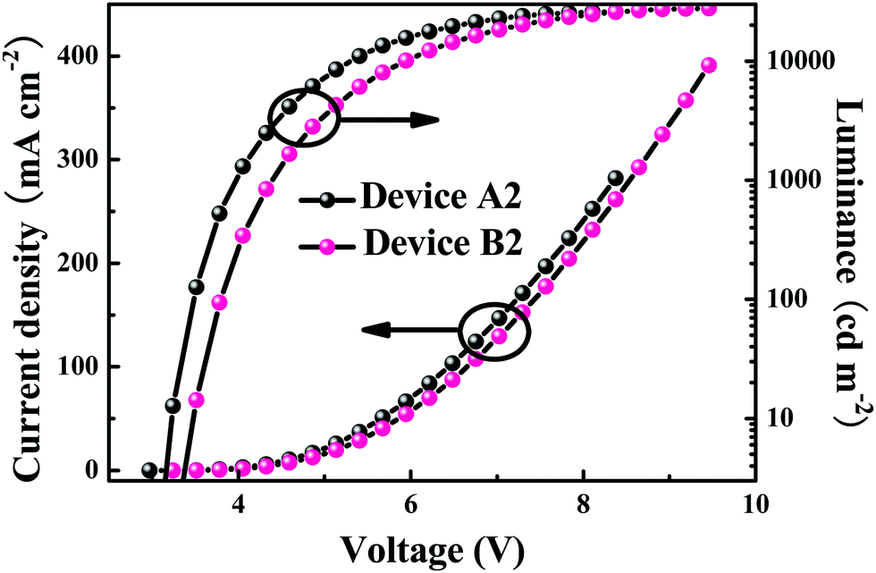 | ||
| Fig. 5 Current density (J)–voltage (V)–luminance (L) curves for the optimized devices A2 and B2. | ||
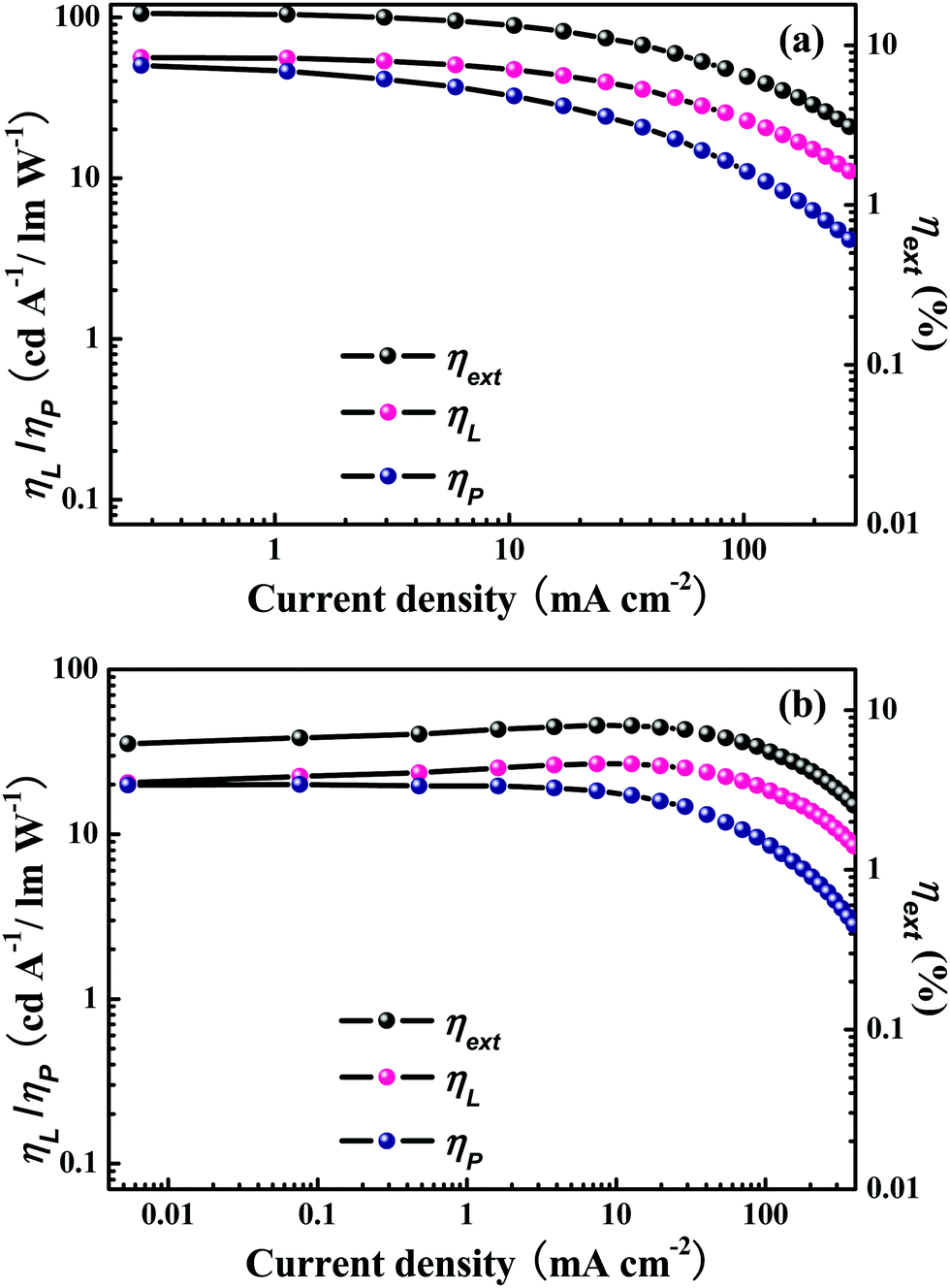 | ||
| Fig. 6 Relationship between EL efficiencies and current density for the optimized devices (a) A2 and (b) B2. | ||
From the aforementioned EL results of the monochromic PhOLEDs, the optimized devices can be turned on at low voltages of ca. 3.0 V (Table 4). Even at a high luminance of 1000 cd m−2, the optimized device A2 can still furnish decent EL efficiencies of 13.5%, 53.5 cd A−1 and 42.1 lm W−1 (Table 4 and Fig. 6). Recently, heteroleptic thiazole-based IrIII analogues have been developed to show maximum EL efficiencies of 23.62 cd A−1, 7.87% and 13.46 lm W−1 with the CBP host in PhOLEDs fabricated by vacuum deposition.25 Functionalized thiazole-based IrIII phosphorescent emitters with a TPA group have furnished attractive EL efficiencies of 39.97 cd A−1, 14.82% and 34.95 lm W−1.24 In addition, high EL efficiencies of 30.84 cd A−1, 12.88% and 26.17 lm W−1 have been achieved by IrIII complexes bearing the 2-phenylthiazole-type ligand. Heteroleptic thiazole-based IrIII phosphorescent emitters with picolinic acid derivatives as ancillary ligands can bring EL efficiencies of 10.98 cd A−1, 6.08% and 6.89 lm W−1 in solution-processed OLEDs.26 Compared with the aforementioned high EL performances achieved by thiazole-based IrIII phosphorescent emitters, the great potential of these two homoleptic complexes in achieving high device efficiencies can be clearly seen.
Both the PL and EL spectra (Fig. 1 and 4) of the two homoleptic thiazole-based IrIII complexes display a double-peak pattern, which can furnish emission bands in different wavelength regions. So, these phosphorescent emitters should show advantage to fabricate WOLEDs. Furthermore, our previous WOLEDs with thiazole-based IrIII phosphorescent emitters bearing a TPA functional group showed undesired voltage-dependent white EL spectra.24 Hence, it is necessary to construct highly efficient WOLEDs with these phosphorescent emitters to show stable white EL spectra. Considering high EL efficiencies as one of the preferential parameters for WOLEDs, Ir-3Tz1F with the higher EL performances was chosen to fabricate WOLEDs using the cheap and convenient solution-process technique. The configuration of the solution-processed WOLEDs is shown in Fig. 7. In addition to Ir-3Tz1F, the well-known blue phosphorescent FIrpic and the pure-red phosphorescent Ir-G1 were employed to fulfill Red–Green–Blue (R–G–B) WOLEDs. All the three phosphorescent emitters were co-doped in PVK and OXD-7 to form an emission layer by a simple spin-coating strategy. In order to optimize the EL performances, the ratio among the three phosphorescent emitters were tuned in the trichromatic WOLEDs.
 | ||
| Fig. 7 Structure of the phosphorescent WOLEDs based on Ir-3Tz1F together with both the energy diagram and molecular structures of the relevant compounds used in these devices. | ||
For device W1 with a weight ratio for FIrpic (Blue, B), Ir-3Tz1F (Green, G) and Ir-G1 (Red, R) (B–G–R ratio) of 40:1.4:0.4, its EL spectra under a low driving voltage showed a red-emission dominated pattern (Fig. 8a). With increasing the driving voltage, the blue and green EL bands were enhanced to furnish a more balanced EL pattern (Fig. 8a). It is clear that both the EL spectra and the CIE coordinates of device W1 are quite unstable with the variation in the driving voltage (Table 5 and Fig. 8a, 9). The voltage-dependent EL spectra in device W1 can be explained as follows. From the energy-level diagram involved in these WOLEDs, it can be seen clearly that the red emitter Ir-G1 possesses a high HOMO level due to the electron-rich TPA group used to furnish a strong hole-trapping ability (Fig. 7). Hence, the injected holes in the emission layer can be easily trapped by Ir-G1. At the same time, the LUMO level of Ir-G1 is very close to that of FIrpic and Ir-3Tz1F. Therefore, the charge carriers injected in a small number at a low driving voltage can easily recombine on Ir-G1 molecules to enhance the red EL band in the EL spectra. This situation will greatly reduce the chance of charge recombination on FIrpic and Ir-3Tz1F molecules and weaken the EL bands from FIrpic and Ir-3Tz1F. In addition, the inevitable cascade energy transfer processes from FIrpic to Ir-3Tz1F and then to Ir-G1 enhance the red EL band. Hence, device W1 exhibits red-emission dominated EL spectra at low driving voltages. However, with increasing the driving voltage, too many charge carriers are injected into the emission layer to be consumed by the Ir-G1 molecules due to their low content in the emission layer. A lot of the remaining charge carriers can recombine on FIrpic and Ir-3Tz1F molecules to substantially enhance the blue and green EL bands (Fig. 8a), and the cascade energy transfer processes cannot effectively weaken the blue and green EL bands due to the low content of Ir-G1. Hence, device W1 exhibits voltage-dependent EL spectra (Fig. 8a). From the discussion above, it is clear that the red emitter Ir-G1 can play a critical role in inducing the undesired voltage-dependent EL spectra.
 | ||
| Fig. 8 EL spectra of the WOLEDs at different driving voltages. (a) W1, (b) W2 and (c) W3. | ||
| WOLEDs | ||||
|---|---|---|---|---|
| W1 | W2 | W3 | ||
| B–G–R ratio = 40:1.4:0.4 |
B–G–R ratio = 40:1.4:0.25 |
B–G–R ratio = 40:1.24:0.26 |
||
| a Maximum values. | ||||
| V turn-on (V) | 3.7 | 3.4 | 3.5 | |
| Luminance La (cd m−2) | 9300 | 12052 |
11890 |
|
| η ext (%) | 16.4 | 14.8 | 16.5 | |
| η L (cd A−1) | 31.3 | 34.6 | 33.4 | |
| η p (lm W−1) | 25.5 | 31.8 | 30.6 | |
| CIE/CRI | 4 V | (0.40, 0.43)/78 | (0.33, 0.47)/70 | (0.35, 0.45)/79 |
| 5 V | (0.39, 0.43)/81 | (0.33, 0.47)/68 | (0.35, 0.45)/80 | |
| 6 V | (0.38, 0.43)/82 | (0.32, 0.47)/66 | (0.35, 0.45)/79 | |
| 7 V | (0.38, 0.44)/83 | (0.32, 0.47)/67 | (0.34, 0.45)/78 | |
| 8 V | (0.37, 0.44)/83 | (0.32, 0.47)/67 | (0.34, 0.45)/78 | |
| 9 V | (0.37, 0.43)/83 | (0.32, 0.46)/67 | (0.34, 0.45)/78 | |
| 10 V | (0.36, 0.43)/82 | (0.32, 0.46)/68 | (0.34, 0.45)/78 | |
| 11 V | (0.36, 0.43)/82 | (0.32, 0.46)/69 | (0.34, 0.44)/78 | |
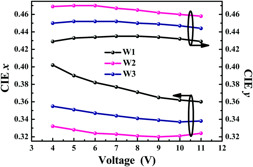 | ||
| Fig. 9 Dependence of the CIE coordinates of the solution-processed WOLEDs on the driving voltages. | ||
In order to weaken the effect of the red emitter Ir-G1 in inducing unstable white EL spectra, the most feasible way is to reduce the content of the red emitter Ir-G1 in the emission layer. Based on this idea, device W2 with a B–G–R ratio of 40:1.4:0.25 in its emission layer was constructed. Encouragingly, both the EL spectra and the CIE coordinates of device W2 can be maintained as very stable in a wide range of driving voltages (Fig. 8b, 9 and Table 5). The much lower content of Ir-G1 in the emission layer of device W2 will effectively eliminate its negative effect on the charge carrier recombination on FIrpic and Ir-3Tz1F molecules as well as on the cascade energy transfer processes. Accordingly, the EL spectra of device W2 can be maintained as very stable in a wide range of driving voltages (Fig. 8b).
Typically, red emitters exhibit relatively lower EL efficiencies. Hence, compared with those of device W1, the EL efficiencies of device W2 were improved due to the lower content of Ir-G1 (Table 5 and Fig. S5, S6, ESI†). Device W2 could furnish peak EL efficiencies of 34.6 cd A−1, 14.8% and 31.8 lm W−1 (Fig. S5 and S6, ESI†), representing some of the most attractive EL performances ever achieved by solution-processed R–G–B WOLEDs. Despite the high EL efficiencies and stable white EL spectra, device W2 displayed relatively unbalanced white EL spectra with a low red-light component. As a result, the white light emitted from device W2 possessed a low color rendering index (CRI) of generally <70 (Table 5). Clearly, device W2 showed green-dominated white EL spectra. Hence, one of the most feasible ways to achieve balanced white EL spectra is to reduce the content of Ir-3Tz1F in the emission layer. From the EL behaviors of both W1 and W2, a higher content of Ir-G1 can evidently increase the red-light component in the white light EL spectra and reduce the EL efficiencies at the same time. Therefore, a reasonable strategy for achieving the optimized trade-off among stable balanced white EL spectrum, high EL efficiency and high CRI is to reduce the content of Ir-3Tz1F in the emission layer as well as to slightly increase the Ir-G1 content. Hence, device W3 with a B–G–R ratio of 40:1.24:0.26 was fabricated. From the EL performances, it can be seen that device W3 could achieve a maximum luminance of 11890 cd m−2 (Fig. 10 and Table 5). Importantly, device W3 showed much more balanced stable white EL spectra with a CRI of about 80 than device W2 while maintaining high EL efficiencies of 33.4 cd A−1, 16.5% and 30.6 lm W−1 (Fig. 11 and Table 5), nearly identical to device W2. Hence, an excellent trade-off among stable balanced white EL spectrum, high EL efficiency and high CRI was successfully fulfilled in device W3. Thiazole-based IrIII phosphorescent complexes have been rarely introduced into WOLEDs. In our previous work, we prepared orange phosphorescent thiazole-based IrIII complexes with a TPA functional group to construct WOLEDs through both vacuum deposition and solution-processing strategies.24 The highest EL efficiencies of the concerned WOLEDs were 22.72 cd A−1, 9.06% and 17.28 lm W−1. In addition, the white EL spectra of the devices exhibited serious voltage-dependent characters, with the highest CRI of ca. 72.24 To the best of our knowledge, device W3 represents the most state-of-the-art WOLED made from thiazole-based IrIII phosphorescent emitters.
 | ||
| Fig. 10 Current density (J)–voltage (V)–luminance (L) curves for the optimized device W3. | ||
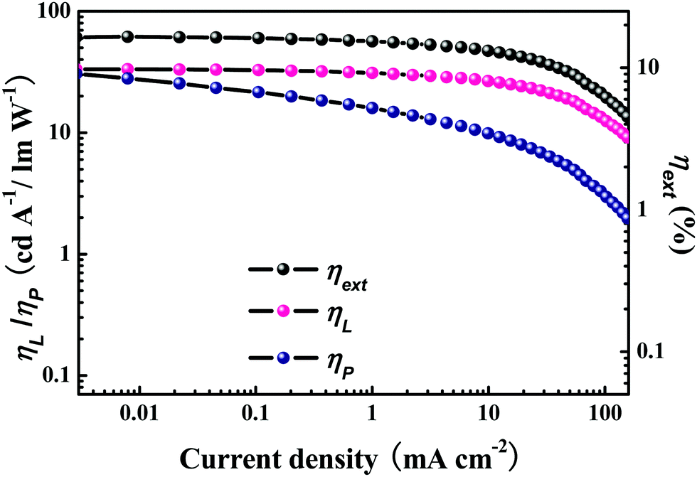 | ||
| Fig. 11 Relationship between the EL efficiencies and the current density for the optimized device W3. | ||
Conclusions
Two homoleptic thiazole-based cyclometalated IrIII phosphorescent complexes were successfully developed. Their thermal stability, photophysical properties, electrochemistry and EL performances were carefully investigated. Owing to their advanced photophysical and electrochemical features, the phosphorescent homoleptic thiazole-based IrIII emitters exhibited high EL efficiencies in monochromic PhOLEDs with ηext of 15.8%, ηL of 56.2 cd A−1 and ηp of 50.2 lm W−1. Importantly, an excellent trade-off between stable a balanced white EL spectrum and a high EL efficiency was successfully realized in solution-processed trichromatic WOLEDs based on these homoleptic thiazole-based IrIII phosphorescent emitters. The optimized solution-processed WOLED with three primary colors showed very attractive EL efficiencies of 33.4 cd A−1, 16.5% and 30.6 lm W−1, while maintaining both high a CRI of ca. 80 and very stable white EL spectra in a wide voltage range. All these decent results represent the top-ranking EL performances ever achieved by thiazole-based IrIII phosphorescent emitters, indicating their great potential in the field of PhOLEDs.Acknowledgements
This research was financially supported by the Fundamental Research Funds for the Central Universities (cxtd2015003), The Program for New Century Excellent Talents in University, the Ministry of Education of China (NECT-09-0651), the Key Creative Scientific Research Team in Shaanxi Province (2013KCT-05), the China Postdoctoral Science Foundation (Grant no. 20130201110034, 2014M562403), and the National Natural Science Foundation of China (no. 20902072, 21572176). The financial support from State Key Laboratory for Mechanical Behavior of Materials is also acknowledged. W.-Y. W. acknowledges the financial support from the National Basic Research Program of China (973 Program, grant no. 2013CB834702), the Areas of Excellence Scheme, University Grants Committee of HKSAR, China (AoE/P-03/08), Hong Kong Research Grants Council (HKBU 12304715), Hong Kong Baptist University (FRG1/14-15/084) and the Hong Kong Polytechnic University.References
- W.-Y. Wong, S.-M. Chan, K.-H. Choi, K.-W. Cheah and W.-K. Chan, Macromol. Rapid Commun., 2000, 21, 453 CrossRef CAS.
- X. Yang, G. Zhou and W. Y. Wong, Chem. Soc. Rev., 2015, 44, 8484 RSC.
- S. Lamansky, P. Djurovich, D. Murphy, F. Abdel-Razzaq, H.-E. Lee, C. Adachi, P. E. Burrows, S. R. Forrest and M. E. Thompson, J. Am. Chem. Soc., 2001, 123, 4304 CrossRef CAS PubMed.
- A. Tsuboyama, H. Iwawaki, M. Furugori, T. Mukaide, J. Kamatani, S. Igawa, T. Moriyama, S. Miura, T. Takiguchi, S. Okada, M. Hoshino and K. Ueno, J. Am. Chem. Soc., 2003, 125, 12971 CrossRef CAS PubMed.
- Y. Chi and P. T. Chou, Chem. Soc. Rev., 2010, 39, 638 RSC.
- Y. You and S. Y. Park, Dalton Trans., 2009, 1267 RSC.
- L. Xiao, Z. Chen, B. Qu, J. Luo, S. Kong, Q. Gong and J. Kido, Adv. Mater., 2011, 23, 926 CrossRef CAS PubMed.
- X. Yang, X. Xu, J. Zhao, J. Dang, Z. Huang, X. Yan, G. Zhou and D. Wang, Inorg. Chem., 2014, 53, 12986 CrossRef CAS PubMed.
- X. Xu, X. Yang, Y. Wu, G. Zhou, C. Wu and W.-Y. Wong, Chem. – Asian J., 2015, 10, 252 CrossRef CAS PubMed.
- C. Fan and C. Yang, Chem. Soc. Rev., 2014, 43, 6439 RSC.
- Q. Wang, I. W. Oswald, X. Yang, G. Zhou, H. Jia, Q. Qiao, Y. Chen, J. Hoshikawa-Halbert and B. E. Gnade, Adv. Mater., 2014, 26, 8107 CrossRef CAS PubMed.
- C. W. Tang and S. A. Vanslyke, Appl. Phys. Lett., 1987, 51, 913 CrossRef CAS.
- J. Kido, M. Kimura and K. Nagai, Science, 1995, 267, 1332 CrossRef CAS PubMed.
- J.-L. Liao, Y. Chi, Y.-D. Su, H.-X. Huang, C.-H. Chang, S.-H. Liu, G.-H. Lee and P.-T. Chou, J. Mater. Chem. C, 2014, 2, 6269 RSC.
- H. B. Wu, L. Ying, W. Yang and Y. Cao, Chem. Soc. Rev., 2009, 38, 3391 RSC.
- J. Brooks, Y. Babayan, S. Lamansky, P. I. Djurovich, I. Tsyba, R. Bau and M. E. Thompson, Inorg. Chem., 2002, 41, 3055 CrossRef CAS PubMed.
- R. Wang, D. Liu, H. Ren, T. Zhang, H. Yin, G. Liu and J. Li, Adv. Mater., 2011, 23, 2823 CrossRef CAS PubMed.
- D. Liu, H. Ren, L. Deng and T. Zhang, ACS Appl. Mater. Interfaces, 2013, 5, 4937 CAS.
- R. Wang, D. Liu, H. Ren, T. Zhang, X. Wang and J. Li, J. Mater. Chem., 2011, 21, 15494 RSC.
- R. Wang, L. Deng, T. Zhang and J. Li, Dalton Trans., 2012, 41, 6833 RSC.
- J. Li, R. Wang, R. Yang, W. Zhou and X. Wang, J. Mater. Chem. C, 2013, 1, 4171 RSC.
- J. Dai, K. Zhou, M. Li, H. Sun, Y. Chen, S. Su, X. Pu, Y. Huang and Z. Lu, Dalton Trans., 2013, 42, 10559 RSC.
- X. Xu, Y. Zhao, J. Dang, X. Yang, G. Zhou, D. Ma, L. Wang, W.-Y. Wong, Z. Wu and X. Zhao, Eur. J. Inorg. Chem., 2012, 2278 CrossRef CAS.
- X. Yang, Y. Zhao, X. Zhang, R. Li, J. Dang, Y. Li, G. Zhou, Z. Wu, D. Ma, W.-Y. Wong, X. Zhao, A. Ren, L. Wang and X. Hou, J. Mater. Chem., 2012, 22, 7136 RSC.
- C. Yao, B. Jiao, X. Yang, X. Xu, J. Dang, G. Zhou, Z. Wu, X. Lv, Y. Zeng and W.-Y. Wong, Eur. J. Inorg. Chem., 2013, 4754 CrossRef CAS.
- T. Giridhar, W. Cho, J. Park, J.-S. Park, Y.-S. Gal, S. Kang, J. Y. Lee and S.-H. Jin, J. Mater. Chem. C, 2013, 1, 2368 RSC.
- Q. Wang, J. Ding, D. Ma, Y. Cheng, L. Wang, X. Jing and F. Wang, Adv. Funct. Mater., 2009, 19, 84 CrossRef CAS.
- X. Yang, G. Zhou and W.-Y. Wong, J. Mater. Chem. C, 2014, 2, 1760 RSC.
- K. A. King, P. J. Spellane and R.-J. Watts, J. Am. Chem. Soc., 1985, 107, 1431 CrossRef CAS.
- M. Thelakkat and H.-W. Schmidt, Adv. Mater., 1998, 10, 219 CrossRef CAS.
- G. J. Zhou, W. Y. Wong, B. Yao, Z. Y. Xie and L. X. Wang, Angew. Chem., Int. Ed., 2007, 46, 1149 CrossRef CAS PubMed.
- W. R. Wadt and P. J. Hay, J. Chem. Phys., 1985, 82, 284 CrossRef CAS.
- P. J. Hay and W. R. Wadt, J. Chem. Phys., 1985, 82, 299 CrossRef CAS.
- M. J. Frisch, G. W. Trucks, H. B. Schlegel, G. E. Scuseria, M. A. Robb, J. R. Cheeseman, J. A. Montgomery, T. Vreven Jr., K. N. Kudin, J. C. Burant, J. M. Millam, S. S. Iyengar, J. Tomasi, V. Barone, B. Mennucci, M. Cossi, G. Scalmani, N. Rega, G. A. Petersson, H. Nakatsuji, M. Hada, M. Ehara, K. Toyota, R. Fukuda, J. Hasegawa, M. Ishida, T. Nakajima, Y. Honda, O. Kitao, H. Nakai, M. Klene, X. Li, J. E. Knox, H. P. Hratchian, J. B. Cross, V. Bakken, C. Adamo, J. Jaramillo, R. Gomperts, R. E. Stratmann, O. Yazyev, A. J. Austin, R. Cammi, C. Pomelli, J. W. Ochterski, P. Y. Ayala, K. Morokuma, G. A. Voth, P. Salvador, J. J. Dannenberg, V. G. Zakrzewski, S. Dapprich, A. D. Daniels, M. C. Strain, O. Farkas, D. K. Malick, A. D. Rabuck, K. Raghavachari, J. B. Foresman, J. V. Ortiz, Q. Cui, A. G. Baboul, S. Clifford, J. Cioslowski, B. B. Stefanov, G. Liu, A. Liashenko, P. Piskorz, I. Komaromi, R. L. Martin, D. J. Fox, T. Keith, M. A. Al-Laham, C. Y. Peng, A. Nanayakkara, M. Challacombe, P. M. W. Gill, B. Johnson, W. Chen, M. W. Wong, C. Gonzalez and J. A. Pople, Gaussian 09, revision A.2, Gaussian, Inc., Wallingford, CT, 2009 Search PubMed.
- R. Pis Diez, MullPop, The National University of La Plata, Argentina, 2003 Search PubMed.
- G. Schaftenaar, Molden v3.7, CAOS/CAMM Center Nijmegen, Toernooiveld, Nijmegen, The Netherlands, 2001 Search PubMed.
- J. Zhao, Y. Yu, X. Yang, X. Yan, H. Zhang, X. Xu, G. Zhou, Z. Wu, Y. Ren and W.-Y. Wong, ACS Appl. Mater. Interfaces, 2015, 7, 24703 CAS.
Footnote |
| † Electronic supplementary information (ESI) available: EL data including EL spectra, J–V–L and EL efficiency curves. See DOI: 10.1039/c6tc04011j |
| This journal is © The Royal Society of Chemistry 2017 |