Improved fullerene-free polymer solar cells using a rationally designed binary mixed solution of an electron extracting layer†
Monika
Gupta
ab,
Dong
Yan
ab,
Jiannian
Yao
ab and
Chuanlang
Zhan
 *ab
*ab
aBeijing National Laboratory for Molecular Sciences, CAS key Laboratory of Photochemistry, Institute of Chemistry, Chinese Academy of Sciences, Beijing 100190, P. R. China. E-mail: clzhan@iccas.ac.cn
bUniversity of Chinese Academy of Sciences, Beijing, 100049, P. R. China
First published on 8th August 2018
Abstract
In continuation of the progressive development of cathode interfacial engineering for successfully improving the power conversion efficiency (PCE) of organic solar cells (OSCs), a breakthrough strategy of combining two small organic materials named Alq3 (aluminum tris(8-hydroxyquinolinate)) and QPhPBr (tetraphenylphosphonium bromide) in one solution acting as a cathode interfacial layer (CIL) has been performed. The strong electron extracting property of Alq3 determined previously and the crucial process of vacuum deposition led to our concept to propose this idea of a mixed binary solution processing technique. We successfully delivered a high performance of PCE above 11% with an increased Voc (0.860 V), Jsc (18.38 mA cm−2) and FF (69.85%) using the combination of Alq3 with QPhPBr as a CIL fabricated using a conventional device structure with PBDB-T:ITIC-Th as the blended active layer. The PCE is 2.5-fold higher than the reference device of bare Al cathode (4.38% PCE). Moreover, the binary mixed solution of CIL has shown a better performance than the Ca/Al based device with a PCE value 1.5 times higher than the value of 7.32% of the Ca/Al device. Their attractive performance has promoted a new challenge for new upcoming bulk-heterojunction OSCs in future prospects.
Introduction
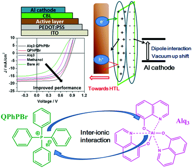
The photoactive layer, the most specific and attractive part of bulk heterojunction (BHJ) organic solar cells (OSCs) based on a mixed solution of donor and acceptor materials, is the major concern of scientists and researchers for developing effectiveness and achieving a high power conversion efficiency comparable to inorganic perovskite1 solar cells. It is quite well known that suitable protection of the photoactive layer, sandwiched between two electrodes, is highly recommended. Several problems have been faced, for example, classical diffusion of oxygen and water, exciton degradation, low lifetime, stability etc. from the direct fabrication of the photoactive layer between electrodes, which causes low performance.2 As one of the most important conditions, the environmental parameters, which greatly influence the stability and lifetime of these OSCs, are critical for the diffusion of oxygen and water into the photoactive layer upper electrode. Thus, it is very important that the permeability of these electrodes should be minimized towards attraction with oxygen and water molecules. To overcome these major deficiencies of OSCs, barrier layers3 which have the ability to protect the photoactive layer from degradation and corrosion processes are used. Such an additional barrier layer atop the active layer in the normal device structure of an OSC has been proposed as a carrier blocking layer because it acts to avoid quenching of carriers at the interface of the active layer/cathode electrode. Until now, various names have been given to this effective barrier layer with its unique properties. Since this barrier layer shows great qualities and proves to have good characteristics for achieving high performance OSCs, we would like to denote it a “cathode interfacial material (CIM).” Its attractive properties include: avoiding the corrosion of the blend photoactive layer, negligible interference in the Vis-IR range of absorption, a low highest occupied molecular orbital (HOMO) energy level, the creation of a good dipole interaction with the cathode electrode in order to adjust the work function with a low barrier space for enriching electron collection, easy fabrication with optimal thickness and semi-transparency for selectively large electron transportation, and improvement of stability and lifetime of BHJ OSCs. Various types of cathode buffer layers (CBLs) have been proposed, for example, metal oxides4 ZnO, TiOx, Nb2O5 and SnOx were identified especially for an inverted device structure. Then, water soluble conjugated polymer5 molecules including PFN, PEI, and PAA were developed and successfully used. Later on, fullerene based salts6 with better matching of the lowest unoccupied molecular orbital (LUMO) energy level to the corresponding fullerene electron acceptor were introduced. In a similar trend, small molecule perylene diimide based neutral PDIN and ionic PDINO7 were also successfully designed. Further, many more metal salts/complexes, sol–gel derivatives, carbon-based materials, organic–inorganic hybrid8 materials, graphene9 and its derivative based quantum dots as interlayers have been systemically reported. Mostly either single layer10 or bilayer compositions11 of such CBLs were applied in earlier reports. Recently, our group has introduced a new function of an electron extraction layer (EEL) composed of a mixed solution of two small molecules containing an ionic environment which creates an ion-exchange framework that possesses a high electron affinity and promotes easy extraction and transportation of electrons towards the cathode electrode.12 Their realistic advantages in the improvement of (PCE) power conversion efficiency results suggest that a mixed blend solution of such an EEL may have a different mechanism strategy for efficient charge extraction. The possible mechanism proposed is that once the two materials are mixed together in solution, a coulombic force attraction is produced between their ionic species. Their continuous interaction and ion-exchange push all the cationic species to one side and their prospective anions on the other side. This layered complex binding structure may preferentially creates a strong electron affinity towards the acceptor material of the active layer interface and the resultant higher possibility of electron extraction taking place. The schematic mechanism is presented in Fig. 1. On one side negative ions passivate the dipole interaction with the positive cathode and adjust it into the proper position for the collection of electrons. During this process, whenever free positive carriers come across the EEL from the exciton dissociated interface, the deep HOMO level of the EEL pushes them back.Thus, overall our strategy of a mixed blend solution of an EEL fabricated on top of an active layer potentially provides a good platform and has the benefits of improving the open-circuit voltage (Voc), the short-circuit current density (Jsc), and fill factor (FF), and finally succeeds in achieving a large output of PCE. Previously, He et al. demonstrated the effect of a PFN CBL for the significant enhancement of Voc, Jsc, and FF in polymer solar cells (PSCs), achieving high efficiency.13 Based on the above important facts and the proposed mechanism of a new function of a blend binary mixed solution of M-EEL (mixed electron extraction layer), we have progressed towards a new combination of two small molecules, aluminium tris(8-hydroxyquinoline) (Alq3) and tetraphenyl phosphonium bromide (QPhPBr). For instance, it has been already justified that Alq3 has efficient properties as a CBL and provides improvement in the lifetime of OSCs.14 Alq3 was previously deposited under vacuum conditions, adopting both an inverted and layer by layer device configuration where control of the layer thickness is very crucial and challenging. Moreover Alq3 was employed using a single layer or bilayer deposition technique with metal or metal halides.11d,15 We observed that Alq3 has good solubility in polar solvents like methanol and can easily mix well with QPhPBr. Hence, after considering all the conditions stated above of these two small molecules acting as an EEL, in this article we proposed the progressive aspects of the binary function of an EEL fabricated on a non-fullerene based blend active layer substrate. Protective encapsulation of the photoactive layer with a binary blend EEL in order to achieve an efficient performance of BHJ OSCs was systemically presented with relevant experimental studies. The photoactive layer was composed of a well-known polymer donor PBDB-T blended with a recently developed thiophene based non-fullerene electron acceptor material ITIC-Th in the presence of 1% chloronaphthalene (CN) additive. Note that using ITIC-Th as an electron acceptor for blend binary devices achieves a PCE of ∼10%16 under inverted device configurations. There has been a ternary solar cell composition reported with a PCE of above 11%.17 Until now, there have been no reports of using a PBDB-T polymer donor combined with ITIC-Th in a binary solar cell system fabricated under conventional configurations. Of the three reference device configurations with CBLs of Ca/Al, only Al and methanol/Al were also taken into consideration. To explain our satisfactory results from the binary behaviour of EEL, the comparative performance of their single molecules was also predicted. All the EEL conditions were fabricated using a standard conventional device configuration: ITO/PEDOT:PSS/active layer/CBL/Al. The molecular structure of the polymer donor, acceptor and cathode buffer layer material are shown in Fig. 2.
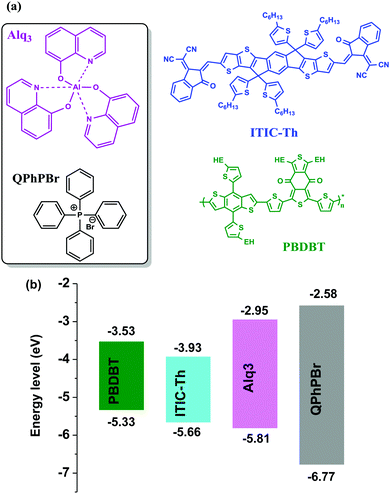 | ||
| Fig. 2 Molecular structures (a) and HOMO and LUMO energy alignments (b) of the materials used in this study: donor PBDB-T, acceptor ITIC-Th, CIL substrates Alq3 and QPhPBr. | ||
Results and discussion
The conventional device structures of the PBDB-T:ITIC-Th blend active layer with five different CBL encapsulation treatments were fabricated and their respective J–V characteristics are shown in Fig. 3 and Table 1. The optimal Alq3–QPhPBr weight ratio is 1![[thin space (1/6-em)]](https://www.rsc.org/images/entities/char_2009.gif) :
:![[thin space (1/6-em)]](https://www.rsc.org/images/entities/char_2009.gif) 1.5 (Table S1, ESI†). All the device parameters were examined in series starting from bare Al and moving towards a single solution (Alq3 or QPhPBr) followed by a blend mixture of a binary solution of Alq3:QPhPBr as the CBL. The optimized thickness condition (∼12 nm) of each CBL material was used in fabrication (Table S2, ESI†). It was determined that a thickness of CBL of less than 12 nm is not sufficient for protection of the active layer to avoid direct contact of the Al cathode and with a thickness of above 12 nm, hindrance of electron transport from the electron acceptor to the Al cathode takes place and causes high series resistance. Data are given in the ESI† documents. Moving from the bare Al cathode to binary Alq3:QPhPBr, a large improvement in the Voc from 0.634 V to 0.860 V was observed. A large improvement in Voc from the new blend buffer layer is attributed to the low energy loss and proper tuning of the low cathode work function via dipole interaction, which induces a band bending mechanism between the cathode interfacial layer and the Al cathode, creating excellent ohmic contact and preventing space charge under the device working condition. The relative increase of Voc from the initial to the highest CBL was calculated as 0.634 < 0.731 < 0.815 < 0.844 < 0.860 for bare Al, methanol treatment, Alq3 solution, QPhPBr solution and Alq3:QPhPBr mixture, respectively. Next, parameter Jsc also showed effective variation by replacing the bare Al cathode condition to insertion of the mixed blend buffer layer. The highest Jsc of 18.38 mA cm−2 was measured using a blend mixture which is comparatively 35% higher than the bare Al cathode observed at 13.67 mA cm−2. Also, the single buffer layer material presented a lower response of Jsc as 15.78 mA cm−2 from methanol treatment, 16.57 mA cm−2 from Alq3 and 17.41 mA cm−2 from QPhPBr buffer layer.
1.5 (Table S1, ESI†). All the device parameters were examined in series starting from bare Al and moving towards a single solution (Alq3 or QPhPBr) followed by a blend mixture of a binary solution of Alq3:QPhPBr as the CBL. The optimized thickness condition (∼12 nm) of each CBL material was used in fabrication (Table S2, ESI†). It was determined that a thickness of CBL of less than 12 nm is not sufficient for protection of the active layer to avoid direct contact of the Al cathode and with a thickness of above 12 nm, hindrance of electron transport from the electron acceptor to the Al cathode takes place and causes high series resistance. Data are given in the ESI† documents. Moving from the bare Al cathode to binary Alq3:QPhPBr, a large improvement in the Voc from 0.634 V to 0.860 V was observed. A large improvement in Voc from the new blend buffer layer is attributed to the low energy loss and proper tuning of the low cathode work function via dipole interaction, which induces a band bending mechanism between the cathode interfacial layer and the Al cathode, creating excellent ohmic contact and preventing space charge under the device working condition. The relative increase of Voc from the initial to the highest CBL was calculated as 0.634 < 0.731 < 0.815 < 0.844 < 0.860 for bare Al, methanol treatment, Alq3 solution, QPhPBr solution and Alq3:QPhPBr mixture, respectively. Next, parameter Jsc also showed effective variation by replacing the bare Al cathode condition to insertion of the mixed blend buffer layer. The highest Jsc of 18.38 mA cm−2 was measured using a blend mixture which is comparatively 35% higher than the bare Al cathode observed at 13.67 mA cm−2. Also, the single buffer layer material presented a lower response of Jsc as 15.78 mA cm−2 from methanol treatment, 16.57 mA cm−2 from Alq3 and 17.41 mA cm−2 from QPhPBr buffer layer.
| ETL | V oc (V) | J sc (mA cm−2) | J cacl (mA cm−2) | FF (%) | PCEMaxb (%) | PCEAvec (%) | μ e (10−4) cm2 V−1 s−1 | R s (Ω cm2) | R sh (kΩ cm2) | ||||||||||||||||||||||||||||||||||||||||||||||||||||||||||||||||||||||||||||||||||||||||||
|---|---|---|---|---|---|---|---|---|---|---|---|---|---|---|---|---|---|---|---|---|---|---|---|---|---|---|---|---|---|---|---|---|---|---|---|---|---|---|---|---|---|---|---|---|---|---|---|---|---|---|---|---|---|---|---|---|---|---|---|---|---|---|---|---|---|---|---|---|---|---|---|---|---|---|---|---|---|---|---|---|---|---|---|---|---|---|---|---|---|---|---|---|---|---|---|---|---|---|---|
| a Calculated from the EQE spectrum. b The best performing device was prepared under the optimal conditions as provided in the methods section. c The statistical results were obtained from 25 cells. | |||||||||||||||||||||||||||||||||||||||||||||||||||||||||||||||||||||||||||||||||||||||||||||||||||
| Al | 0.634 ± 0.004 | 13.67 ± 0.42 | 12.11 | 50.61 ± 1.16 | 4.38 | 3.95 ± 0.43 | 2.19 ± 0.15 | 25.55 ± 0.20 | 0.68 ± 0.11 | ||||||||||||||||||||||||||||||||||||||||||||||||||||||||||||||||||||||||||||||||||||||||||
| MeOH | 0.731 ± 0.006 | 15.78 ± 0.38 | 14.68 | 64.44 ± 1.64 | 7.43 | 7.08 ± 0.35 | 3.79 ± 0.11 | 18.86 ± 0.25 | 0.76 ± 0.07 | ||||||||||||||||||||||||||||||||||||||||||||||||||||||||||||||||||||||||||||||||||||||||||
| Alq3 | 0.815 ± 0.002 | 16.57 ± 0.41 | 15.81 | 67.92 ± 1.38 | 9.17 | 8.92 ± 0.25 | 3.85 ± 0.25 | 15.68 ± 0.18 | 0.92 ± 0.08 | ||||||||||||||||||||||||||||||||||||||||||||||||||||||||||||||||||||||||||||||||||||||||||
| QPhPBr | 0.844 ± 0.003 | 17.41 ± 0.45 | 16.74 | 69.11 ± 1.55 | 10.15 | 9.74 ± 0.41 | 4.10 ± 0.12 | 8.78 ± 0.20 | 1.25 ± 0.10 | ||||||||||||||||||||||||||||||||||||||||||||||||||||||||||||||||||||||||||||||||||||||||||
| Alq3:QPPBr | 0.860 ± 0.004 | 18.38 ± 0.31 | 17.5 | 69.85 ± 0.77 | 11.05 | 10.83 ± 0.22 | 4.17 ± 0.18 | 6.22 ± 0.14 | 1.87 ± 0.12 | ||||||||||||||||||||||||||||||||||||||||||||||||||||||||||||||||||||||||||||||||||||||||||
| Ca/Al | 0.792 ± 0.002 | 15.26 ± 0.35 | — | 60.73 ± 1.75 | 7.32 | 6.89 ± 0.43 | — | — | — | ||||||||||||||||||||||||||||||||||||||||||||||||||||||||||||||||||||||||||||||||||||||||||
J sc depends upon the full spectrum range of absorption from the blend photoactive layer and morphological characteristics. Without CBL encapsulation, degradation of its surface generally occurs due to exposure of moisture and air which can be easily understood from the bare Al condition response. However, the significant increase of Jsc from the blend mixture of CBL compared to the single buffer layer suggests that their combination would have provided a better tendency of the number of excitons absorbed within the lifetime period and makes them more stable. The increase of Jsc performance occurs in the order 18.38 > 17.41 > 16.57 > 15.78 > 13.67 from Alq3:QPhPBr > QPhPBr > Alq3 > methanol > bare Al, respectively. Moreover, the high Jsc from such a new buffer layer can be also explained due to the fact that the optimized thickness behaviour over the active layer accompanies the reduction in the electron trap state during Al deposition, while the decrease in Jsc from thicknesses of CBL over 12 nm gives a suitable explanation (see ESI† documents). Additionally, the higher Jsc output stimulated under the light J–V curve was further configured with external quantum efficiency (EQE) measurements (Fig. 3b). EQE spectra from different CBL conditions show good absorption in a wide range of 360–800 nm. The EQE spectrum is further improved while changing CBL from the bare Al cathode to the binary buffer layer. Notably, the calculated Jsc from the product of the EQE integration demonstrated for the devices with different condition of the interlayer perfectly matches with the value measured from its J–V characteristics.
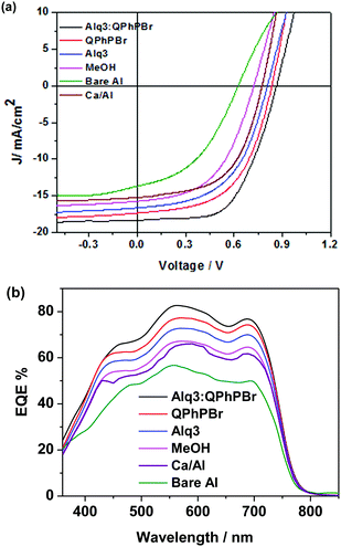 | ||
| Fig. 3 (a) Under light illumination, J–V characteristic curves of PBDB-T:ITIC-Th based blend active layer under different coating of CBL substrates. (b) Their corresponding EQE spectra. | ||
The third important parameter to take into consideration is the FF. The large built in potential resulting in greater exciton dissociation creates a number of free charge carriers followed by improved mobility of the carriers in proper channels and avoids recombination loss, corresponding to a high FF of the given devices. For instance, better density packing and surface morphology acquire easy charge transportation and collection at the respective electrodes, which is also a beneficial process. Thus, a proper methodology of fabrication with a suitable thickness and film forming ability of the active layer followed by suitable protection coating with optimized thickness of CBL are collectively responsible for achieving a high FF. Effective coating of a new blend mixture of CBL Alq3:QPhPBr over the active layer shows an FF of 69.85%, which is much higher than the value of 50.61% without CBL coating from bare Al as well as with methanol treatment condition (64.44%). A further slight improvement in the FF was observed from single CBL coating 67.92% from Alq3 and 69.11% from QPhPBr, which proves that the combined behaviour of a mixed solution reaches the top limit of electron extraction, transportation and collection. Additionally, they were capable of pushing back hole carriers to the opposite electrode and improved the electron to hole mobility ratio due to the existence of the deep HOMO energy level. Hence the total PCE which is defined by multiplication of three controlling parameters, Voc, Jsc and FF is attributed to 11.05, 10.15, 9.17, 7.43 and 4.38%, corresponding to Alq3:QPhPBr, QPhPBr, Alq3, methanol and bare Al, respectively. The total 2.5 fold increase in PCE was demonstrated from the binary mixture of Alq3:QPhPBr CBL in comparison to the bare Al cathode. Moreover, the comparative performance with the Ca/Al CBL condition was also measured and observed at Voc of 0.79 V, Jsc of 15.26 mA cm−2 and FF of 60.73% (Table 1). These results proved that our new binary mixture solution of CBL has the capability to replace the well-known standard CBL condition of vacuum deposition Ca/Al process to attain highly efficient photovoltaic cells. The absorption properties using UV-Vis absorption spectroscopy were characterized for CBL. Their negligible or transparent behaviour in the full visible and near IR region supports them as ideal substrates for new buffer layer treatments. The absorption spectrum of each buffer substrate and blend active layer thin film is presented in Fig. 4a. Their corresponding HOMO, LUMO energy (Fig. 2b) and band gap were estimated from ultraviolet photoelectron spectroscopy (UPS) measurements (Fig. S1 and Tables S3, S4, ESI†). The deep high HOMO energy level of these new buffer substrates below the level of the active layer promotes hole blocking activity and lowers the recombination process.
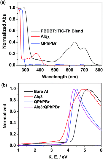 | ||
| Fig. 4 (a) Absorption spectra of thin films of QPhPBr, Alq3 and the blend active layer, (b) normalized work function plot of different CBL conditions using the UPS method. | ||
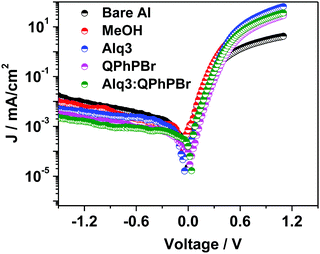
Again, the ultraviolet photoelectron spectroscopy (UPS) based work function characteristics of different coatings of the CBL layer were estimated to give a clear explanation of the high Voc and the data are shown in Fig. 4b. The decrease in the kinetic energy (KE) value was observed and accordingly the work function was calculated. The resultant experimental data clearly shows that the binary mixture of CBL Alq3:QPhPBr shows an upshift in the vacuum level of 3.96 eV. However, from the single material treatment Alq3 was observed at 3.6 eV and 4.06 eV from QPhPBr. All the three conditions were upshifted from the bare Al electrode occurring at 4.25 eV. The estimated value of the work function from the new binary buffer properly matching with the LUMO energy level of the electron acceptor promotes easy accessibility of the electron transport towards the cathode and improved band bending property. However, from treatment with Alq3 or QPhPBr, a small increase in the distance of energy matching with the LUMO electron acceptor would be the reason for the lower performance compared to the binary mixture. Furthermore, the dark current–density study with the different condition of the CBL coating was also monitored to understand the detailed origin of the improved device performance shown in Fig. 5. The low current density appears at a negative bias, corresponding to a reduction in the leakage of current of the devices, which is closely related to the blocking effect of Al diffusion. It was observed that the binary buffer layer of Alq3:QPhPBr has the lowest leakage current response than other CBL conditions. On the other hand, bare Al possesses a high level of leakage current at negative bias, revealing that the effective blocking phenomenon from the new binary buffer layer is highly recommended. The highest shift in the voltage of the Alq3:QPhPBr based device compared to that of the bare Al cathode confirms the best ohmic contact formation and perfect band bending effect at the interface between the interlayer and cathode and consequently agrees well for the improved Voc of the device. Hence it can be explained that band bending is one of the reasons for the high Voc in the Alq3:QPhPBr based device.
Next, we move to explore a more in-depth investigation of our J–V data supported by the light source dependence on Jsc study and the Jphvs. Vint measurements. The experimental power law dependence of the photocurrent on the incident light intensity and the resultant plot of the net photocurrent (Jph = JL − JD) dependence on the effective applied voltage Veff are shown in Fig. 6a and b. Logarithmic plots of different CBL encapsulations indicate that the power exponent from both QPhPBr and the binary buffer interlayer Alq3:QPhPBr reaches 1.00 which is much higher than the exponent power result of the bare Al cathode appearing at 0.84, confirming that there is a rare possibility of a build-up of net space charges even at the highest illumination intensity.18 This describes the appearance of a high electric field and high charge carrier motilities even at low effective voltage and consequently prevents bimolecular recombination losses.
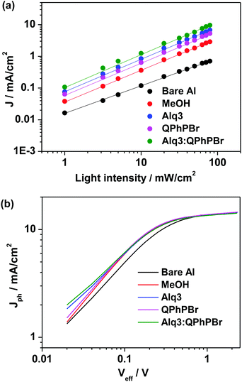 | ||
| Fig. 6 (a) Light intensity dependent short circuit current density plots, (b) Jphvs. Veff plots under different optimized condition of CBLs. | ||
Another experimental study of the net photocurrent dependence (Jph = JD − JL) vs. effective applied voltage (Veff) applied for different cathode buffer interlayer conditions also proves that incorporation of such a binary mixture new buffer interlayer provides an improved charge collection efficiency under working conditions. The Jph − Veff characteristics of the Alq3:QPhPBr based device approaches a 94% value at a net photocurrent density of saturation, while the single buffer layer coated device shows a lower response. For example, at maximal power output conditions, Jph/Jsat for bare Al, methanol, Alq3 and QPhPBr based CBL devices reaches 90%, 93%, 93.3% and 93.5%, respectively. A drastic improvement in the Jph/Jsat value by incorporation of the Alq3:QPhPBr interlayer indicates a superior exciton dissociation into free carriers and subsequently the collection of all the free carriers at the electrodes with minimized bimolecular losses.18 Such a bimolecular recombination reduction in the new scenario of the cathode buffer layer based device is responsible for the high charge mobility therein. Since charge transport19 is described by the given Einstein equation D = (KBT/e) × μ. Where D = diffusion coefficient, KB is the Boltzmann constant, T is the temperature; e is the electron charge and μ is the mobility. Thus, the enhancement in charge diffusion followed by the charge transport is collectively responsible for the distinctly different Jph/Jsat values when compared with the reference device.
In general, the large electron extraction and collection at the cathode electrode can be observed due to the high mobility of carriers as demonstrated by using the space charge limited current (SCLC)20 model. The hole mobility of the active layer was estimated to be 1.59 × 10⁻⁴ cm2 V−1 s−1 (Fig. S2, ESI†). Considering the central role of the CBL for efficient hole blocking and charge mobility influencing the device performance, moving from the bare Al cathode to the new binary mixture cathode buffer layer, successive improvement in electron mobility from 2.19 × 10⁻⁴ to 4.17 × 10⁻⁴ guarantees efficient electron transport during the charge collection process for achieving high efficiency. However, for other CBL conditions, the electron mobility was calculated as 3.79 × 10⁻⁴, 3.85 × 10⁻⁴, 4.10 × 10⁻⁴ for methanol, Alq3 and QPhPBr, respectively (Fig. 7a).
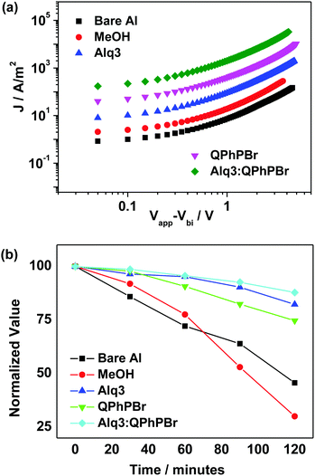 | ||
| Fig. 7 (a) Electron mobility characteristics of different CBL encapsulations, (b) variation with time of the normalized efficiency of OSCs with different CBLs. | ||
It is a well-known fact that the degradation probability of solar cell devices without encapsulation of any cathode buffer layer depends on two severe conditions:21 (1) air and moisture exposure into the active layer causes instability and reduces lifetime and (2) the phenomenon involving diffusion of the cathode metal into the active layer during deposition. In this regard, we have demonstrated how the long stability of the proposed device can be achieved in the presence of a new CBL substrate introduced between the active layer and cathode. In order to estimate the lifetime stability of the device in different CBL fabrication, we kept each cell in continuous air exposure for 2 h. The performance of the J–V curve was monitored after 30 minute intervals and the results are presented in Fig. 7b. Without encapsulation of CBL, rapid degradation within one hour occurred, whereas, the binary buffer layer provides high stability with slow degradation in the power conversion efficiency. It was shown that the Alq3:QPhPBr based device decreased by 14% while the devices based on Alq3 and QPhPBr were attributed to a degradation rate of 18% and 25%, respectively. However, the bare Al cathode and methanol treated device degraded much faster by 50% and 70%, respectively, in a similar time duration of air exposure. For instance, it was also observed that if these devices were kept under a nitrogen environment, they would be stable for several days. Thus it is expected that encapsulation to shield from water and oxygen can make the lifetime of such OSCs even longer.
Additionally, we performed AFM surface morphology analysis for differently encapsulated ETL. It was found that the mixed binary layer of Alq3:QPhPBr shows a large reduction in the surface roughness appearing at 3.95 nm which is much smaller than that of the control device occurring at 7.95 nm as well as from single CBL treatment (5.26 nm and 4.12 nm from Alq3 and QPhPBr, respectively). This suggests that we need to gain a moderate roughness size by incorporating a suitable ETL to improve device efficiency. Detailed discussion and images are provided in Fig. S3 (ESI†).
X-ray diffraction experiments of Alq3, QPhPBr, and their binary mixture films were conducted and their data are shown in Fig. 8. All three films are highly crystalline with multi diffraction bands clearly shown. Compared to the pure Alq3 and QPhPBr films, the mixture film exhibits a much different diffraction spectrum, in which the band positions are shifted and the band intensity becomes intense or weak. The comparisons of the XRD data clearly indicated that Alq3 and QPhPBr mixed to form a new species, for example, through the intermolecular ππ-interaction between Alq3 8-hydroxyquinolinate and QPhPBr benzene and dipolar-static interactions between Alq3 and QPhPBr, which may explain the different tuning in the metal work function and different output of the device performance compared to their individual counterpart based CILs.
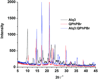 | ||
| Fig. 8 The XRD data of the CBL materials, Alq3, QPhPBr and their binary mixture on the silica substrate. | ||
Conclusions
The effective roles of five different conditions of cathode buffer interlayers using a PBDB-T:ITIC-Th blend active layer were demonstrated. By comparing their drastic features in different CBL fabrications, it was evident that insertion of a blend binary mixture of Alq3:QPhPBr under optimized thickness and weight ratio conditions is beneficial for improving device performance with Voc, 0.860 V; Jsc, 18.38 mA cm−2; FF, 69.85% and total PCE of 11.05% being achieved. The purpose of such a binary layer was also to mitigate the slow degradation process under air exposure to achieve long term stability and lifetime. In contrast, without encapsulation of CBL between the active layer and the metal cathode, rapid degradation occurs as serious damage of the active layer leads to reduced diode property, a large space charge barrier and finally lowers solar cell efficiency. However, based on a systematic study of the correlation between the OSC performance and the mixed binary layer of the organic cathode buffer material properties, this provides basic guidelines for further application of small molecule organic CBL materials. These beneficial findings and proposed mechanism may in turn have commercial interest for developing new display technology that offers alternatives to the current flat panel display. Their relatively highly efficient performance intends to focus on more challenging and superior development of new ideas for CBL promotion.Conflicts of interest
There are no conflicts to declare.Acknowledgements
The authors gratefully acknowledge the financial support funded by the National Natural Science Foundation of China (NSFC, No. 21773262, 91433202, and 21221002), Chinese Academy of Sciences (CAS, XDB12010200) and CAS President's International Fellowship Initiative (Grant No. 2016PM054).References
- (a) D. Angmo, X. Peng, J. Cheng, M. Gao, N. Rolston, K. Sears, C. Zuo, J. Subbiah, S.-S. Kim, H. C. Weerasinghe, R. H. Daustkardt and D. Vak, ACS Appl. Mater. Interfaces, 2018, 10, 22143 CrossRef PubMed; (b) M.-H. Li, H.-H. Yeh, Y.-H. Chiang, U. S. Jeng, C.-J. Su, H.-W. Shiu, Y.-J. Hsu, N. Kosugi, T. Ohigashi, Y.-A. Chen, P.-S. Shen, P. Chen and T.-F. Guo, Adv. Mater., 2018, e1801401 CrossRef PubMed; (c) C. Ma, D. Shen, M. F. Lo and C.-S. Lee, Angew. Chem., Int. Ed., 2018, 57, 9941 CrossRef PubMed; (d) P.-Y. Gu, N. Wang, C. Wang, Y. Zhou, G. Long, M. Tian, W. Chen, X. W. Sun, M. G. Kanatzidis and Q. Zhang, J. Mater. Chem. A, 2017, 5, 7339 RSC; (e) L. Zhang, X. Liu, J. Li and S. McKechnie, Sol. Energy Mater. Sol. Cells, 2018, 175, 1 CrossRef; (f) Z. Jia, T. Jiu, Y. Li and Y. Li, Mater. Chem. Front., 2017, 1, 2261 RSC.
- H. Ju, K. M. Knesting, W. Zhang, X. Pan, C.-H. Wang, Y. W. Yang, D. S. Ginger and J. Zhu, ACS Appl. Mater. Interfaces, 2016, 8, 2125 CrossRef PubMed.
- (a) B. Walker, H. Choi and J. Y. Kim, Curr. Appl. Phy., 2017, 17, 370 CrossRef; (b) J. Min, Y. N. Luponosov, Z.-G. Zhang, S. A. Ponomarenko, T. Ameri, Y. Li and C. J. Brabec, Adv. Energy Mater., 2014, 4, 1400816 CrossRef; (c) N. Wang, K. Zhao, T. Ding, W. Liu, A. S. Ahmed, Z. Wang, M. Tian, X. W. Sun and Q. Zhang, Adv. Energy Mater., 2017, 7, 1700522 CrossRef; (d) L. Lv, X. Wang, T. Dong, X. Wang, X. Wu, L. Yang and H. Huang, Mater. Chem. Front., 2017, 1, 1317 RSC.
- (a) M. Tountas, Y. Topal, A. Verykios, A. Soultati, A. Kaltzoglou, T. A. Papadopoulos, F. Auras, K. Seintis, M. Fakis, L. C. Palilis, D. Tsikritzis, S. Kennou, A. Fakharuddin, L. Schmidt-Mende, S. Gardelis, M. Kus, P. Falaras, D. Davazoglou, P. Argitis and M. Vasilopoulou, J. Mater. Chem. C, 2018, 6, 1459 RSC; (b) T. Van-Huong, R. Khan, I.-H. Lee and S.-H. Lee, Sol. Energy Mater. Sol. Cells, 2018, 179, 260 CrossRef; (c) Y. Choi, G. Kim, H. Kim, S. H. Kim and K. Lee, Thin Solid Films, 2015, 583, 86 CrossRef.
- (a) D. Zhou, X. Cheng, H. Xu, H. Yang, H. Liu, F. Wu, L. Chen and Y. Chen, J. Mater. Chem. A, 2016, 4, 18478 RSC; (b) H. Wang, W. Zhang, C. Xu, X. Bi, B. Chen and S. Yang, ACS Appl. Mater. Interfaces, 2013, 5, 26 CrossRef PubMed; (c) J.-S. Yeo, M. Kang, Y.-S. Jung, R. Kang, S.-H. Lee, Y.-J. Heo, S.-H. Jin, D.-Y. Kim and S.-I. Na, Nano Energy, 2016, 21, 26 CrossRef; (d) Y. Zhou, C. Fuentes-Hernandez, J. Shim, J. Meyer, A. J. Giordano, H. Li, P. Winget, T. Papadopoulos, H. Cheun, J. Kim, M. Fenoll, A. Dindar, W. Haske, E. Najafabadi, T. M. Khan, H. Sojoudi, S. Barlow, S. Graham, J.-L. Bredas, S. R. Marder, A. Kahn and B. Kippelen, Science, 2012, 336, 327 CrossRef PubMed; (e) B. A. E. Courtright and S. A. Jenekhe, ACS Appl. Mater. Interfaces, 2015, 7, 26167 CrossRef PubMed.
- (a) C. Cui, Y. Li and Y. Li, Adv. Energy Mater., 2017, 7 Search PubMed; (b) X. Liu, W. Jiao, M. Lei, Y. Zhou, B. Song and Y. Li, J. Mater. Chem. A, 2015, 3, 9278 RSC; (c) W. Jiao, D. Ma, M. Lv, W. Chen, H. Wang, J. Zhu, M. Lei and X. Chen, J. Mater. Chem. A, 2014, 2, 14720 RSC; (d) J. W. Jung, J. W. Jo and W. H. Jo, Adv. Mater., 2011, 23, 1782 CrossRef PubMed.
- (a) Z.-G. Zhang, B. Qi, Z. Jin, D. Chi, Z. Qi, Y. Li and J. Wang, Energy Environ. Sci., 2014, 7, 1966 RSC; (b) J.-l. Wu, W.-K. Huang, Y.-C. Chang, B.-C. Tsai, Y.-C. Hsiao, C.-Y. Chang, C.-T. Chen and C.-T. Chen, J. Mater. Chem. A, 2017, 5, 12811 RSC.
- Z. Zheng, Q. Hu, S. Zhang, D. Zhang, J. Wang, S. Xie, R. Wang, Y. Qin, W. Li, L. Hong, N. Liang, F. Liu, Y. Zhang, Z. Wei, Z. Tang, T. P. Russell, J. Hou and H. Zhou, Adv. Mater., 2018, 30, 1801801 CrossRef PubMed.
- (a) H. B. Yang, Y. Q. Dong, X. Wang, S. Y. Khoo, B. Liu and C. M. Li, Sol. Energy Mater. Sol. Cells, 2013, 117, 214 CrossRef; (b) L. Zhang, Z. C. Ding, T. Tong and J. Liu, Nanoscale, 2017, 9, 3524 RSC; (c) H. B. Yang, Y. Q. Dong, X. Wang, S. Y. Khoo and B. Liu, ACS Appl. Mater. Interfaces, 2014, 6, 1092 CrossRef PubMed.
- (a) L. Zhang, C. Liu, T. Lai, H. Huang, X. Peng, F. Huang and Y. Cao, J. Mater. Chem. A, 2016, 4, 15156 RSC; (b) D.-X. Yuan, X.-D. Yuan, Q.-Y. Xu, M.-F. Xu, X.-B. Shi, Z.-K. Wang and L.-S. Liao, Phys. Chem. Chem. Phys., 2015, 17, 26653 RSC.
- (a) Z. Huai, L. Wang, Y. Sun, R. Fan, S. Huang, X. Zhao, X. Li, G. Fu and S. Yang, ACS Appl. Mater. Interfaces, 2018, 10, 5682 CrossRef PubMed; (b) J. Min, H. Zhang, T. Stubhan, Y. N. Luponosov, M. Kraft, S. A. Ponomarenko, T. Ameri, U. Scherf and C. J. Brabec, J. Mater. Chem. A, 2013, 1, 11306 RSC; (c) H. I. Kim, B. Thi Thu Trang, G.-W. Kim, G. Kang, W. S. Shin and T. Park, ACS Appl. Mater. Interfaces, 2014, 6, 15875 CrossRef PubMed; (d) A. Singh, A. Dey, D. Das and P. K. Iyer, ACS Appl. Mater. Interfaces, 2016, 8, 10904 CrossRef PubMed; (e) A. Singh, A. Dey, D. Das and P. K. Iyer, J. Mater. Chem. C, 2017, 5, 6578 RSC.
- (a) W. Li, D. Yan, W. liu, J. Chen, W. Xu, C. Zhan and J. Yao, Sol. RRL, 2017, 1, 1700014 CrossRef; (b) M. Gupta, D. Yan, J. Xu, J. Yao and C. Zhan, ACS Appl. Mater. Interfaces, 2018, 10, 5569 CrossRef PubMed; (c) Y. D. Monika Gupta, Shen Fugang, Xu Jianzhong and Zhan Chuanlang, Acta Phys. Chim. Sin, 2018, 34(X) DOI:10.3866/PKU.WHXB201805101; (d) W. Liu, W. Li, J. Yao and C. Zhan, Chin. Chem. Lett., 2018, 28, 381 Search PubMed; (e) W. Li, D. Yan, F. Liu, T. Russell, C. Zhan and J. Yao, Sci. China: Chem., 2018, 62 DOI:10.1007/s11426-018-9320-3.
- Z. He, C. Zhong, X. Huang, W.-Y. Wong, H. Wu, L. Chen, S. Su and Y. Cao, Adv. Mater., 2011, 23, 4636 CrossRef PubMed.
- (a) Y. Lare, B. Kouskoussa, K. Benchouk, S. O. Djobo, L. Cattin, M. Morsli, F. R. Diaz, M. Gacitua, T. Abachi, M. A. del Valle, F. Armijo, G. A. East and J. C. Bernede, J. Phys. Chem. Solids, 2011, 72, 97 CrossRef; (b) Q. L. Song, F. Y. Li, H. Yang, H. R. Wu, X. Z. Wang, W. Zhou, J. M. Zhao, X. M. Ding, C. H. Huang and X. Y. Hou, Chem. Phys. Lett., 2005, 416, 42 CrossRef; (c) C. Zhang, P. Zhang, X. Xu, Y. Dang, X. Chen and B. Kang, Mater. Lett., 2016, 164, 591 CrossRef.
- Z. El Jouad, L. Barkat, N. Stephant, L. Cattin, N. Hamzaoui, A. Khelil, M. Ghamnia, M. Addou, M. Morsli, S. Bechu, C. Cabanetos, M. Richard-Plouet, P. Blanchard and J. C. Bernede, J. Phys. Chem. Solids, 2016, 98, 128 CrossRef.
- (a) F. Zhao, S. Dai, Y. Wu, Q. Zhang, J. Wang, L. Jiang, Q. Ling, Z. Wei, W. Ma, W. You, C. Wang and X. Zhan, Adv. Mater., 2017, 29, 1700144 CrossRef PubMed; (b) Z. Li, K. Jiang, G. Yang, J. Y. L. Lai, T. Ma, J. Zhao, W. Ma and H. Yan, Nat. Commun., 2016, 7, 13094 CrossRef PubMed; (c) Y. Lin, F. Zhao, Q. He, L. Huo, Y. Wu, T. C. Parker, W. Ma, Y. Sun, C. Wang, D. Zhu, A. J. Heeger, S. R. Marder and X. Zhan, J. Am. Chem. Soc., 2016, 138, 4955 CrossRef PubMed.
- (a) Q. An, F. Zhang, W. Gao, Q. Sun, M. Zhang, C. Yang and J. Zhang, Nano Energy, 2018, 45, 177 CrossRef; (b) Y. Chen, P. Ye, X. Jia, W. Gu, X. Xu, X. Wu, J. Wu, F. Liu, Z.-G. Zhu and H. Huang, J. Mater. Chem. A, 2017, 5, 19697 RSC; (c) W. Chen and Q. Zhang, J. Mater. Chem. C, 2017, 5, 1275 RSC.
- M. Lenes, M. Morana, C. J. Brabec and P. W. M. Blom, Adv. Funct. Mater., 2009, 19, 1106 CrossRef.
- V. D. Mihailetchi, L. J. A. Koster, J. C. Hummelen and P. W. M. Blom, Phys. Rev. Lett., 2004, 93, 216601 CrossRef PubMed.
- G. G. Malliaras, J. R. Salem, P. J. Brock and C. Scott, Phys. Rev. B: Condens. Matter Mater. Phys., 1998, 58, 13411 CrossRef.
- P. Peumans, V. Bulovic and S. R. Forrest, Appl. Phys. Lett., 2000, 76, 2650 CrossRef.
Footnote |
| † Electronic supplementary information (ESI) available. See DOI: 10.1039/c8qm00311d |
| This journal is © the Partner Organisations 2018 |

