DOI:
10.1039/C7RA11676D
(Paper)
RSC Adv., 2018,
8, 1583-1592
Construction of Cu–Ce/graphene catalysts via a one-step hydrothermal method and their excellent CO catalytic oxidation performance†
Received
23rd October 2017
, Accepted 13th December 2017
First published on 4th January 2018
Abstract
Cu–Ce/graphene catalysts show high dispersion of metal particles and excellent activity and stability for catalytic oxidation. In this study, a hydrothermal method was used to synthesize a series of bimetallic Cu–Ce/graphene catalysts, and the effects of the proportions of Cu and Ce on CO oxidation were investigated in detail. Indispensable characterizations such as XPS, XRD, TEM, BET, and H2-TPR were conducted to explore the effect of the Cu/Ce molar ratio and the metal valence on the activity and determine the structure–performance relationship. The results showed that bimetallic supported catalysts, such as 3Cu5Ce/graphene, 1Cu1Ce/graphene, and 5Cu3Ce/graphene, possessed significant catalytic activity. Especially, the 5Cu3Ce/graphene catalyst showed highest catalytic activity for CO oxidation, the T100 value was 132 °C, and the apparent activation energy was 68.03 kJ mol−1. Furthermore, the stability of the 5Cu3Ce/graphene catalyst was outstanding, which could be maintained for at least 12 h. Moreover, the CeO2 particles were well crystalline with the size 5–9 nm in these catalysts, and the CuO nanoparticles were well dispersed on CeO2 and graphene. Notably, the ratio of Cu/Ce in the catalyst was higher, the interaction between the Ce species and the graphene was stronger, and the Cu species were more easily reduced; this was beneficial for the oxidation of CO.
1. Introduction
With the rapid development of economy and the increase in human activities, environmental pollution is becoming a highly serious problem, and CO is one of the main pollutants. Noble metal catalysts, such as Au, Pt, and Pd catalysts, have excellent catalytic oxidation activity and selectivity for CO oxidation, but they have short service life and high cost and are easily poisoned by sulfide.1 As an alternative noble metal-free catalyst, CuO–CeO2 shows excellent catalytic performance for CO oxidation since CeO2 has the ability to store and release oxygen by redox shift between Ce4+ and Ce3+.2
Jia et al.3 synthesized highly ordered mesoporous Cu–Ce–O catalysts using ordered mesoporous silica KIT-6 as a hard template. When the Cu concentrations were higher than 20 mol%, total CO conversion could be achieved at 160 °C, and they found that direct loading of CuO on the surface of mesoporous CeO2 resulted in large CuO crystals and correspondingly low activity. Wang et al.4 synthesized nanosized Cu–CeO2 composites using a hydrothermal method. It was discovered that the Cu content played a key role in promoting the activity of the Cu/CeO2 catalyst because Cu accelerated the modulation between the cycle transition of Ce4+/Ce3+, oxygen vacancy, and surface area. The nanosized Cu–CeO2 catalyst showed high catalytic activity for selective oxidation of CO at relatively low temperatures. Wang et al.5 prepared CuO/CeO2 catalysts via an improved wetness impregnation method. They changed the content of Cu and found that the catalyst with 10.0 wt% CuO loading had high activity and stability for CO-PROX that was related to the strong interaction of fine-dispersed CuO species with the CeO2 support. Although the Cu–Ce oxide catalysts showed good initial activity, stability was still lacking.
To improve the stability of a catalyst, the active component is usually dispersed and anchored on the support. The support plays an important role in promoting the dispersion of the metal via enhancing the interaction between Cu–Ce. Dong et al.6 prepared CuO–CeO2/SBA-15 catalysts by a solid-state impregnation method, which had well dispersed and reduced ceria particle size. Moreover, solid-state impregnation could increase interfacial CuO–CeO2 entities and strengthen the interaction between CuO and CeO2. Araya et al.7 investigated the effect of the support on the activity of CuO–CeO2 catalysts in CO oxidation. They found that the support had a strong influence on the activity of catalysts, which had noticeable synergistic effects and could strengthen the interaction between the highly dispersed Cu and 3D particles of CeO2.
Notably, graphene has a large specific surface area, which can increase the metal dispersion, and the large pore structure can also provide a transport channel for the reactants and products;8,9 this characteristic makes it an ideal support for catalytic reaction. Hou et al.10 prepared sandwich-like N-doped graphene/Co3O4 catalysts via a one-pot hydrothermal method for selective oxidation of olefins and alcohols. This catalyst exhibited superior activity and stability for the epoxidation of styrene and high compatibility with various olefins and alcohols with good conversion and high selectivity. Liu et al.11 used the conventional impregnation and hydrogen reduction method to prepare Pd/graphene for CO oxidation. The nanoparticles were highly dispersed on the graphene support, and the catalyst showed superior catalytic activity and stability for CO oxidation.
To date, graphene is used as a promising catalytic support to obtain ideal CO catalytic oxidation results due to its large surface area, pore structure, and excellent electric conductivity. However, the distribution, interaction of metal oxides on graphene, and their catalytic performance is still unknown. In this study, a facile one-step hydrothermal method was used to synthesize a series of Cu–Ce/graphene catalysts. Furthermore, the effect of the Cu/Ce molar ratio was investigated in detail, and a series of characterizations (such as XRD, TEM, FTIR and Raman spectroscopy, XPS, and H2-TPR) was conducted to explore the structure–performance relationship.
2. Experimental details
2.1 Synthesis of Cu–Ce/graphene
GO was prepared using a modified Hummers method.12 The typical route of Cu–Ce/graphene synthesis when the mass ratio of metal is 10% is as follows: 0.06 g Cu(NO3)2·3H2O and 0.06 g Ce(NO3)3·6H2O were added to 200 ml of 2 mg ml−1 GO aqueous dispersion and then completely mixed until a homogenous solution was obtained. The 0.5 M Na2CO3 aqueous solution was added dropwise to the mixture until the pH = 9. The mixture was stirred at room temperature for 1 hour. It was then carefully transferred into a 300 ml Teflon-lined stainless steel autoclave. The mixture was heated to 180 °C and maintained at this temperature for 24 h. Subsequently, the autoclave was cooled down to room temperature. The obtained sample was washed with deionized water several times and dried at 60 °C in air. Finally, the sample was calcined at 400 °C for 5 hours under a N2 atmosphere. This product was labeled as 5Cu3Ce/graphene. For comparison, the molar ratios of Cu and Ce were changed to 1![[thin space (1/6-em)]](https://www.rsc.org/images/entities/char_2009.gif) :0, 1:1, 3:5, and 0:1, and the products were labeled as Cu/graphene, 4Cu4Ce/graphene, 3Cu5Ce/graphene, and Ce/graphene, respectively.
:0, 1:1, 3:5, and 0:1, and the products were labeled as Cu/graphene, 4Cu4Ce/graphene, 3Cu5Ce/graphene, and Ce/graphene, respectively.
2.2 Characterization tests
XRD analysis was performed to verify the crystallographic phase present in the Cu–Ce/graphene catalysts. The XRD patterns of the samples were obtained using a Rigaku D/MAX-RB X-ray diffractometer with a target Cu Kα operated at 60 kV and 55 mA at a scanning speed of 0.5° min−1. The 2θ value of the wide-angle ranged from 10° to 80°.
TEM experiments were conducted using a JEOL JEM-2010 transmission electron microscope equipped with an Oxford energy-dispersive X-ray (EDX) spectrometer attachment operating at 200 kV.
A Fourier transform infrared spectroscope (FTIR, Nexus 870FT-IR) was used for obtaining the FTIR spectra of the sample in the range from 400 to 4000 cm−1.
Raman scattering was performed using an RM 2000 microscope confocal Raman spectrometer (Renishaw PLC) with 532 nm laser.
The chemical states of the atoms on the catalyst surface were investigated by X-ray photoelectron spectroscopy (XPS) using a VG ESCALAB 210 Electron Spectrometer (Mg Kα radiation; hm = 1253.6 eV). XPS data were calibrated using the binding energy of C 1s (284.6 eV) as the standard.
Temperature programmed reduction by H2 (H2-TPR) was performed using an online GC-7890II gas chromatograph equipped with a thermal conductivity detector (TCD). The reducing gas was 5 vol% H2 balanced by nitrogen, and a flow rate of 40 ml min−1 was used. The quartz tube reactor was loaded with an 80 mg sample in powder form. The test was carried out from room temperature to 800 °C at a heating rate of 10 °C min−1.
2.3 Measurements of catalytic performance
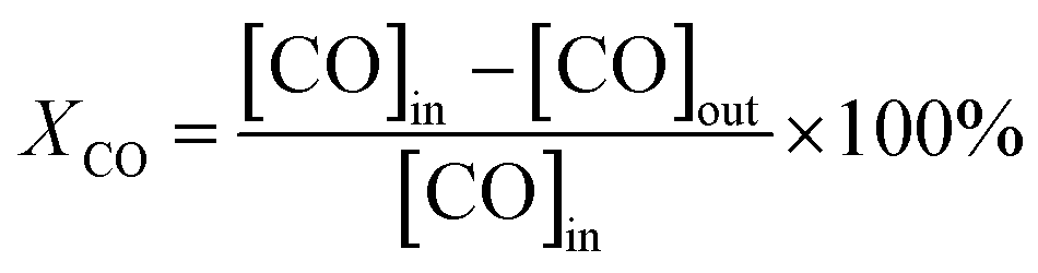
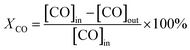
Catalytic activity tests were performed using a continuous-flow fixed-bed microreactor. A glass tube with an inner diameter of 6 mm was chosen as the reactor tube. About 150 mg catalyst with an average diameter of 20–40 mesh was placed in the tube. The reaction gas mixture consisting of 1 vol% CO balanced with air was passed through the catalyst bed at a total flow rate of 25 ml min−1. The typical weight hourly space velocity (WHSV) was 10000 ml g−1 h−1. The composition of the influent and effluent gasses was detected using an online GC-7890II gas chromatograph equipped with a TCD. In this study, this change of moles was neglected. Therefore, the CO conversion was calculated based on the outlet CO:| |
 | (1) |
the [CO]in and [CO]out are the CO concentrations (vol%) in the gas mixture before and after CO oxidation reaction, respectively.
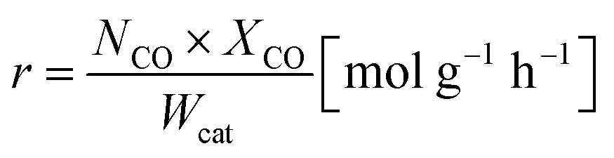
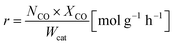
The oxidation rate of CO was calculated by
| |
 | (2) |
NCO is the CO molar flow rate,
XCO is the conversion rate of CO based on CO
2 formation, and
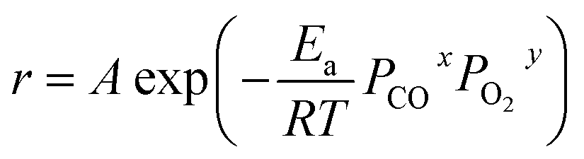
Wcat is the mass of the catalyst in the reactor bed. When the CO conversion was <15%, the influence of the produced CO
2 and H
2O on the reaction rate could be ignored, and the composition of the reactant gas remained essentially unchanged; therefore, ln
A,
xln
PCO, and
yln
PO2 could be approximately considered as constants. The empirical equation of the activation energy is as follows:
| |
 | (3) |
| | |
lnr = lnA + xlnPCO + ylnPO2 − Ea/RT
| (4) |
| | |
lnr = −Ea/RT + C
| (5) |
A is the pre-exponential factor,
R is the ideal gas constant,
T is the reaction temperature,
PCO is the partial pressure of CO, P
O2 is the partial pressure of O
2, and C is a constant, which is equal to ln
A +
xln
PCO +
yln
PO2 under the CO conversion of <15%.
3. Results and discussion
3.1 Physicochemical properties of Cu–Ce/graphene catalysts
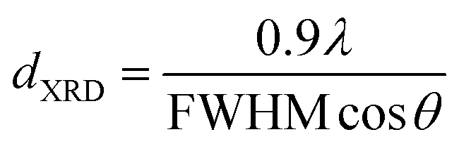
3.1.1 X-ray diffraction studies. The XRD patterns of the Cu–Ce/graphene catalysts with different molar ratios are presented in Fig. 1. It can be seen that all the catalysts exhibit seven reflections at the 2θ values of 28.53°, 33.16°, 47.53°, 56.58°, 69.58°, 76.75°, and 79.32°, which correspond to the (111), (200), (220), (311), (400), (331), and (420) planes ascribed to the face-centered cubic (FCC) fluorite structure of CeO2 (JCPDS 34-0394). The crystalline mean particle sizes of CeO2 have been determined by the X-ray broadening technique employing the Scherrer equation as follows:13
where λ is the X-ray wavelength (15.406 nm), FWHM (in Rad) is the full width at half maximum of the characteristic peak (111) of CeO2, and the θ is the diffraction angle for the (111) plane. The average calculated crystalline sizes of CeO2 were 5.7 nm, 7.2 nm, and 8.9 nm for 3Cu5Ce/graphene, 4Cu4Ce/graphene, and 5Cu3Ce/graphene, respectively. There were two planes of (111) 43.37° and (200) 50.54° attributed to Cu (JCPDS 65-9026), whereas no diffraction peaks belonging to the CuO species were observed; this was because a part of carbon atoms on the surface of graphene as a reductant made CuO transform to Cu in the calcination process.14 Moreover, the redox course: Ce3+ + Cu2+ ↔ Ce4+ + Cu+/Cu0 could generate the reduced state of Cu particles.
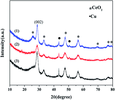 |
| | Fig. 1 XRD patterns of the 3Cu5Ce/graphene (1), 4Cu4Ce/graphene (2), and 5Cu3Ce/graphene (3) catalysts. | |
3.1.2 Morphological characterizations. Fig. S1† exhibits the SEM, TEM, and HRTEM images of Cu–Ce/graphene catalysts. As can be seen from Fig. S1(a–c),† the Cu–Ce/graphene catalysts show excellent fine structures, and the Ce and Cu species are highly dispersed on graphene. It could be clearly observed from Fig. S1(d–g)† that the interplanar spacing d was about 0.32 and 0.27 nm, which was attributed to the (111) and (200) crystal facets of CeO2, respectively. There was no large accumulation of Cu species particles, as shown in the HRTEM image; this further indicated that Cu species were highly dispersed on the surface of graphene or CeO2. The STEM-EDS mapping analysis of the 5Cu3Ce/graphene catalyst further indicated the well-defined spatial distribution of the elements C, O, Ce, and Cu in the catalyst, and the result was consistent with the XRD results.
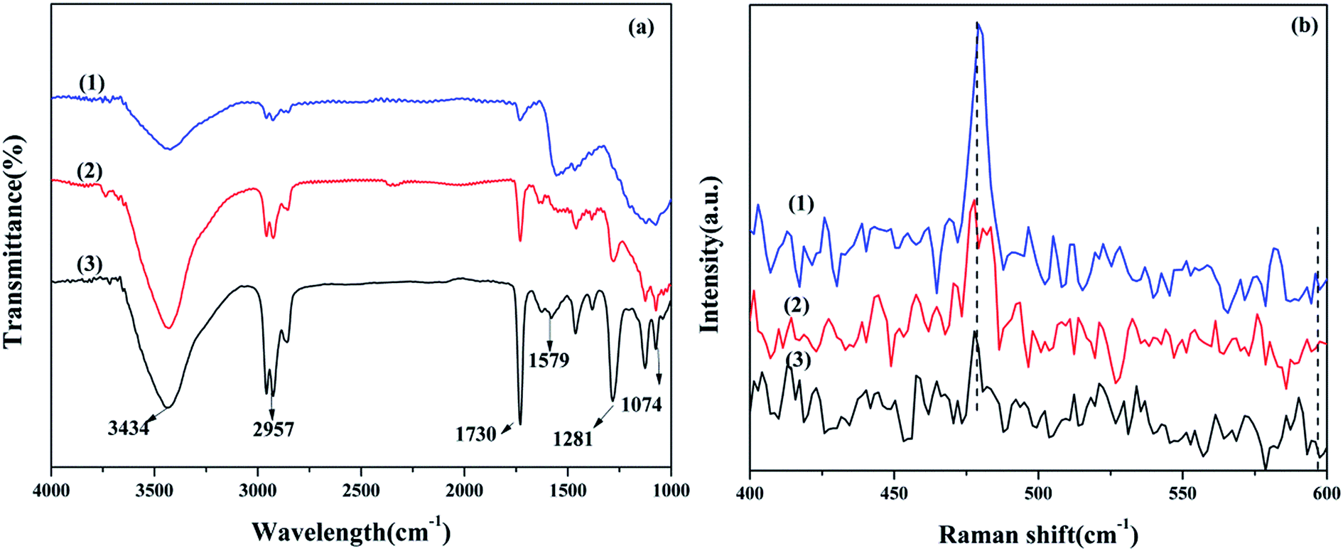
3.1.3 FTIR spectroscopy. The FTIR spectra of Cu–Ce/graphene catalysts are shown in Fig. 2a. Obviously, the absorption peaks at about 3434, 2957, 1730, 1579, 1281, and 1074 cm−1 were attributed to the stretching vibrations of O–H, C–H, C![[double bond, length as m-dash]](https://www.rsc.org/images/entities/char_e001.gif) O, CC, C–OH, and C–O, respectively.15,16 During the calcination process, CuO was reduced by the thermal decomposition of graphene, such that part of CuO was converted into metal Cu, and the oxygen released during the CuO reduction process oxidized graphene. Therefore, the higher ratio of Cu/Ce in the catalysts led to a higher content of oxygen-containing functional groups in graphene. This result was consistent with the conclusions of the XRD analysis. Additionally, the abundant oxygen-containing groups were beneficial for bonding with metal particles and promoting the catalytic oxidation reaction.
O, CC, C–OH, and C–O, respectively.15,16 During the calcination process, CuO was reduced by the thermal decomposition of graphene, such that part of CuO was converted into metal Cu, and the oxygen released during the CuO reduction process oxidized graphene. Therefore, the higher ratio of Cu/Ce in the catalysts led to a higher content of oxygen-containing functional groups in graphene. This result was consistent with the conclusions of the XRD analysis. Additionally, the abundant oxygen-containing groups were beneficial for bonding with metal particles and promoting the catalytic oxidation reaction.
 |
| | Fig. 2 FTIR spectra (a) and Raman spectra (b): 3Cu5Ce/graphene (1), 4Cu4Ce/graphene (2), and 5Cu3Ce/graphene (3). | |
3.1.4 Raman spectroscopy. Raman spectroscopy was used to provide the evidence of oxygen vacancy and defects due to the change in the vibrational structure of the CeO2 lattice.17 As shown in Fig. 2b, all catalysts exhibited a strong F2g Raman vibration mode of the CeO2 fluorite phase at 479 cm−1 with the weak bands at about 595 cm−1, corresponding to the non-degenerate LO mode of ceria due to the relaxation of symmetry rules, which was often linked to oxygen vacancy in the ceria lattice.18,19 The A590/A460 value could reflect the relative concentration of oxygen vacancy.20 It could be seen that the strength of the A460 band decreased gradually with an increase in the Ce species content. However, the strength of the A590 band was almost unchanged; therefore, the value of the A590/A460 increased with a decrease in the Ce species content in the catalysts; this illustrated that the oxygen vacancy in the catalysts increased gradually.
3.1.5 BET analysis. The N2 adsorption/desorption isotherms and pore size distribution of graphite oxide and Cu–Ce/graphene catalysts are shown in Fig. 3. It could be seen from Fig. 4, that graphite oxide did not show the isotherms and the pore structure. The Cu–Ce/graphene catalysts presented type IV isotherms with an H2-type hysteresis loop, which was the typical feature of mesoporous materials, and the pore size distribution was centered at 3.2 nm. Table 1 shows the result of the BET analysis. Apparently, the 3Cu5Ce/graphene catalyst possesses largest specific surface area and large pore volume and would increase the number of reaction active sites and enhance the catalytic activity. With an increase in the Cu/Ce ratio, the specific surface area and pore volume decreased gradually. This indicated that the increase in the Cu/Ce ratio caused the blocking of pores in graphene, and a higher Cu/Ce ratio meant higher redox degree during the calcination process that further decreased the specific surface area and pore volume to a greater extent.
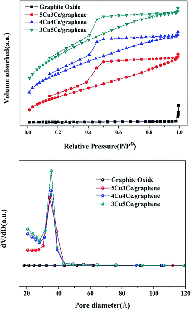 |
| | Fig. 3 N2 adsorption and desorption isotherms and BJH measurements of graphite oxide and Cu–Ce/graphene catalyst. | |
 |
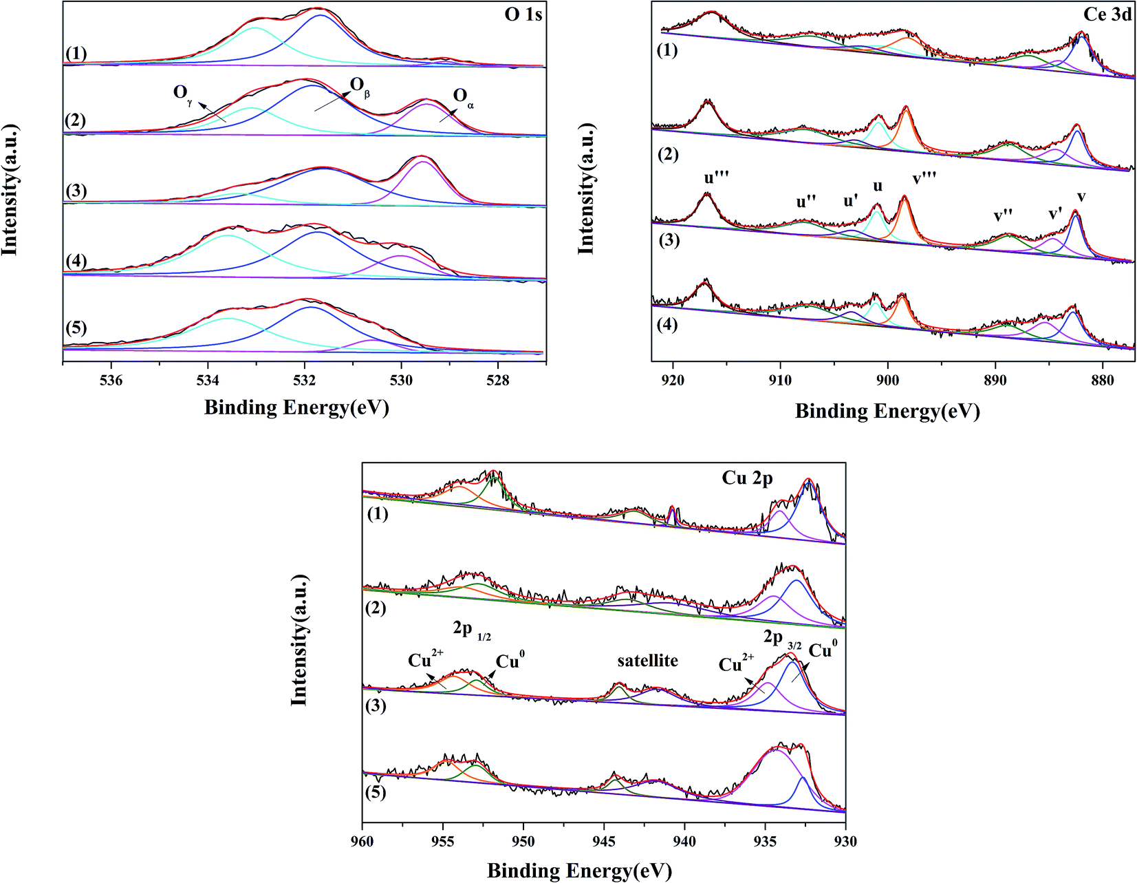
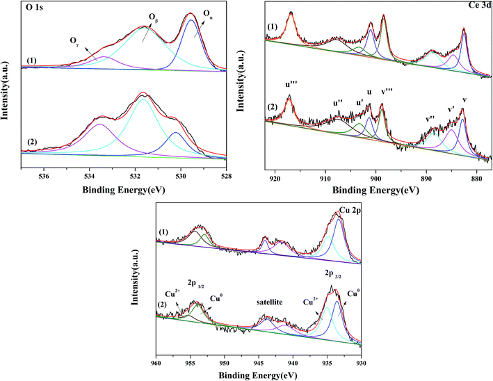
| | Fig. 4 O 1s Ce 3d and Cu 2p XPS spectra of 3Cu5Ce/graphene (1), 4Cu4Ce/graphene (2), 5Cu3Ce/graphene (3), Ce/graphene (4), and Cu/graphene (5) catalysts. | |
Table 1 BET result of graphite oxide and Cu–Ce/graphene catalyst
| Catalysts |
SBET (m2 g−1) |
Vp (cm3 g−1) |
Dp (nm) |
| Graphite oxide |
3.59 |
0.025 |
38.7 |
| 5Cu3Ce/graphene |
206.50 |
0.187 |
3.5 |
| 4Cu4Ce/graphene |
298.91 |
0.221 |
3.2 |
| 3Cu5Ce/graphene |
367.00 |
0.262 |
3.2 |
3.1.6 XPS analysis. X-photoelectron spectroscopy analysis was used to examine the surface composition and the chemical state of the elements present in the Cu–Ce/graphene catalysts. The O 1s spectra of the Cu–Ce/graphene catalysts are shown in Fig. 4. It could be seen that three O 1s peaks appeared in the Cu–Ce/graphene catalysts. The peak at about 529 eV was attributed to the characteristic lattice oxygen of metal oxides, which was named as Oα. The main peaks at about 531 eV named as Oβ corresponded to the surface adsorbed oxygen such as O− or OH−, whereas the peaks at about 533 eV were associated with adsorbed molecular water and named Oγ.21 Table 1 shows the binding energy of O 1s, and the relative percentages of the adsorbed activity O species have been quantified based on the area of their XPS peaks. With an increase in the Cu/Ce molar ratio in these catalysts, the content of the surface adsorbed oxygen in the catalyst increased gradually, which was considered as the active sites to promote the conversion of CO. The more the number of surface adsorbed oxygen, the better the activity of the catalytic oxidation reaction.The spectra of Cu 2p are shown in Fig. 4. All Cu–Ce/graphene catalysts presented the peaks of Cu 2p3/2 at about 932 eV, Cu 2p1/2 at about 953.06 eV, and the satellite peak at 940–945 eV. Each Cu 2p peak could be deconvoluted into two pairs of doublets: the doublet peaks at about 932 eV and 951 eV were assigned to metallic Cu0 or Cu+, and another doublet peaks at about 934 eV and 953 eV corresponded to Cu2+. According to the literature,22 the absence of peaks at about 932 eV was characteristic of the reduced copper species, which included Cu0 and Cu+. Khan et al.23 attributed the peak at about 932 eV to the presence of Cu+. However, Chen et al.24 reported that Cu+ was only the intermediate transition state, which was beneficial for promoting the conversion of Cu2+ to Cu0 at high temperatures. The copper species of these catalysts was consistent with the results of XRD. Therefore, it was concluded that the Cu0 and Cu+ species were present in this series of catalysts. Further, the content of Cu2+ in the catalysts was calculated, as shown in the Table 2. The results verified that the Cu2+/(Cu0 + Cu+ + Cu2+) values were in the order 3Cu5Ce/graphene < 4Cu4Ce/graphene < 5Cu3Ce/graphene.
Table 2 XPS results analysis of the Cu–Ce/graphene catalysts
| Samples |
Ce/graphene |
3Cu5Ce/graphene |
4Cu4Ce/graphene |
5Cu3Ce/graphene |
Cu/graphene |
Used 5Cu3Ce/graphene |
| Cu2+ (%) |
— |
38.24 |
41.44 |
45.41 |
76.37 |
42.10 |
| Ce3+ (%) |
21.25 |
11.85 |
15.02 |
16.87 |
— |
25.48 |
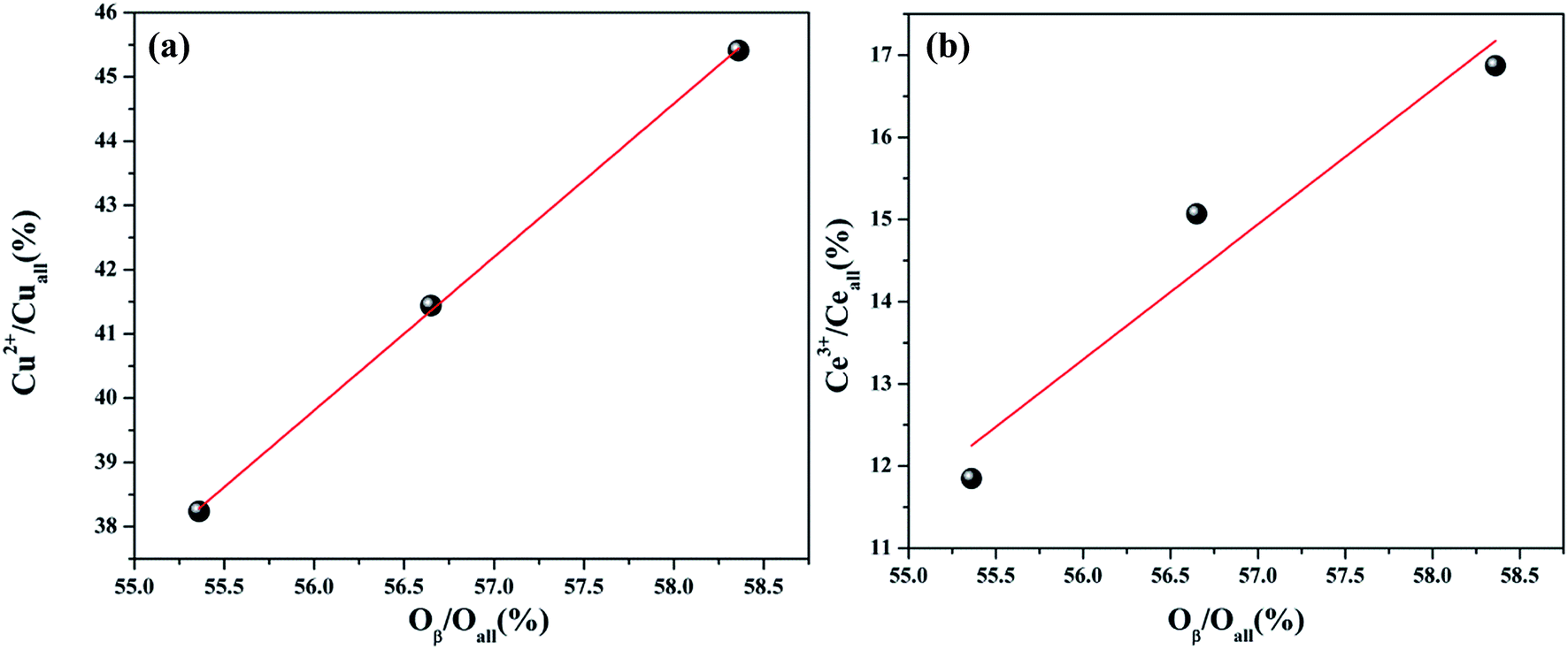
The Ce 3d spectra are shown in Fig. 4, and two groups of spin–orbital multiplets corresponding to Ce 3d3/2 and Ce 3d5/2 have been denoted as u and v, respectively. The bands labeled as u, u′′, and u′′′ and v, v′′, and v′′′ were related to Ce4+, whereas the other two bands labeled as u′ and v′ corresponded to Ce3+. This indicated that cerium on the surface of graphene was present in two different oxidation states: Ce4+ and Ce3+. The presence of Ce4+ was due to the oxidation of Ce3+ during the calcination process, and a part of Ce4+ was originated from the redox: Ce3+ + Cu2+ ↔ Ce4+ + Cu+/Cu0. As observed from Table 2 and the XPS of Cu/graphene and Ce/graphene catalysts, the contents of Cu2+ and Ce3+ in single metal catalysts are much more than those on the bimetallic catalyst. This means that a part of Ce3+ and Cu2+ was reduced by graphene. This further proved that the redox reaction occurred during the calcination process. The presence of the abovementioned reaction was attributed to the interconnection between Ce and Cu.25 In addition, the calculated percentages of Ce3+ for different Cu–Ce/graphene catalysts are shown in Table 2, and the Ce3+/(Ce4+ + Ce3+) values increased with an increase in the Cu/Ce molar ratio. This law of change in the Ce species was consistent with the change in Cu species. Especially, a higher concentration of Ce3+ means that the rich oxygen vacancy was better than that in the CO oxidation reaction. As shown in Fig. 5, the Oβ/Oall and Ce3+/Ceall, Cu2+/Cuall had a great linear relationship. With an increase in Oβ/Oall, the ratio of Ce3+/Ceall, Cu2+/Cuall increased.
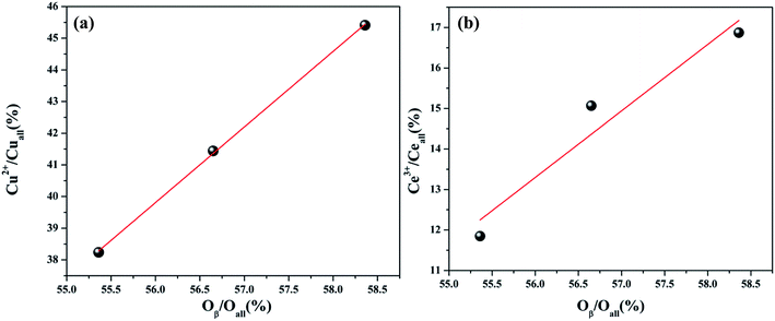 |
| | Fig. 5 The relation between the Cu2+/Cuall (%) and Oβ/Oall (%) (a) and Ce3+/Ceall (%) (b). | |
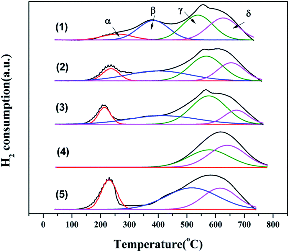
3.1.7 H2-TPR characterization. To investigate the reducibility of this series of Cu–Ce/graphene catalysts, H2-TPR characterization was carried out. The results are shown in Fig. 6, and the position of the peaks is given in Table S2.† The Cu–Ce/graphene catalysts showed a strong peak (α) at 200–250 °C, which could be attributed to the reduction of Cu2+ to Cu0.26 With an increase in the Cu/Ce molar ratio, the peak position moved towards a lower temperature. This phenomenon meant that it was easier to form small particles of Cu, which was more easily reduced and beneficial for the CO catalytic oxidation reaction. The peak (β) at 379–515 °C was assigned to the reduction of poorly dispersed CuO on graphene.27 The peak (γ) at 533–576 °C could be assigned to the reduction of Ce4+ to Ce3+.28 Similar to the case of CuO, the peak position moved towards a low temperature with a continuous increase in the Cu/Ce molar ratio in the catalyst. Compared to the Ce/graphene catalyst, the addition of Cu species promoted the reduction of CeO2. The peak (δ) at 614–671 °C corresponded to the hydrogenation of carbon atoms in graphene.29 The better the combination of the active ingredient with graphene, the less easy the reduction of graphene.
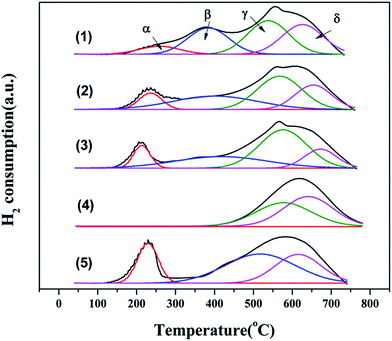 |
| | Fig. 6 H2-TPR patterns of 3Cu5Ce/graphene (1), 4Cu4Ce/graphene (2), 5Cu3Ce/graphene (3), Ce/graphene (4), and Cu/graphene (5) catalysts. | |
3.2 Activity test and kinetic study of CO oxidation over Cu–Ce/graphene catalysts
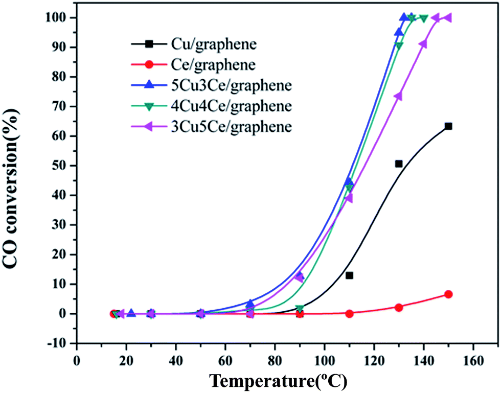
The Cu–Ce/graphene catalysts with different Cu/Ce molar ratios were evaluated for CO oxidation reaction, and the results are shown in Fig. 7. As can be seen in Fig. 7, the total conversion temperature (T100) of the 3Cu5Ce/graphene, 4Cu4Ce/graphene, and 5Cu3Ce/graphene catalysts is 145 °C, 132 °C, and 130 °C, respectively. Notably, the catalytic activity of the Cu/graphene and Ce/graphene catalysts was poor as compared to that of the Cu–Ce/graphene catalysts, especially for Ce/graphene, which showed low activity, and the conversion of CO was only 6.16% at 150 °C. Among all the catalysts, the 5Cu3Ce/graphene catalyst exhibited highest activity. Keeping Pco and Po2 constant, the reaction rates of 3Cu5Ce/graphene, 4Cu4Ce/graphene, and 5Cu3Ce/graphene catalysts at the nearly conversion rate were calculated by changing the reaction temperatures, and the result is exhibited in Fig. S2.†
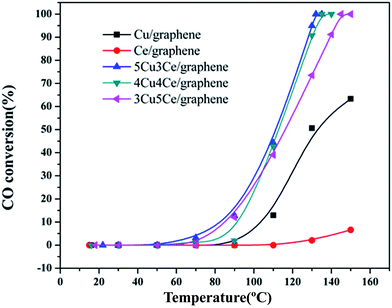 |
| | Fig. 7 Catalytic activity of the 3Cu5Ce/graphene, 4Cu4Ce/graphene, 5Cu3Ce/graphene, Ce/graphene, and Cu/graphene catalysts for CO oxidation. | |
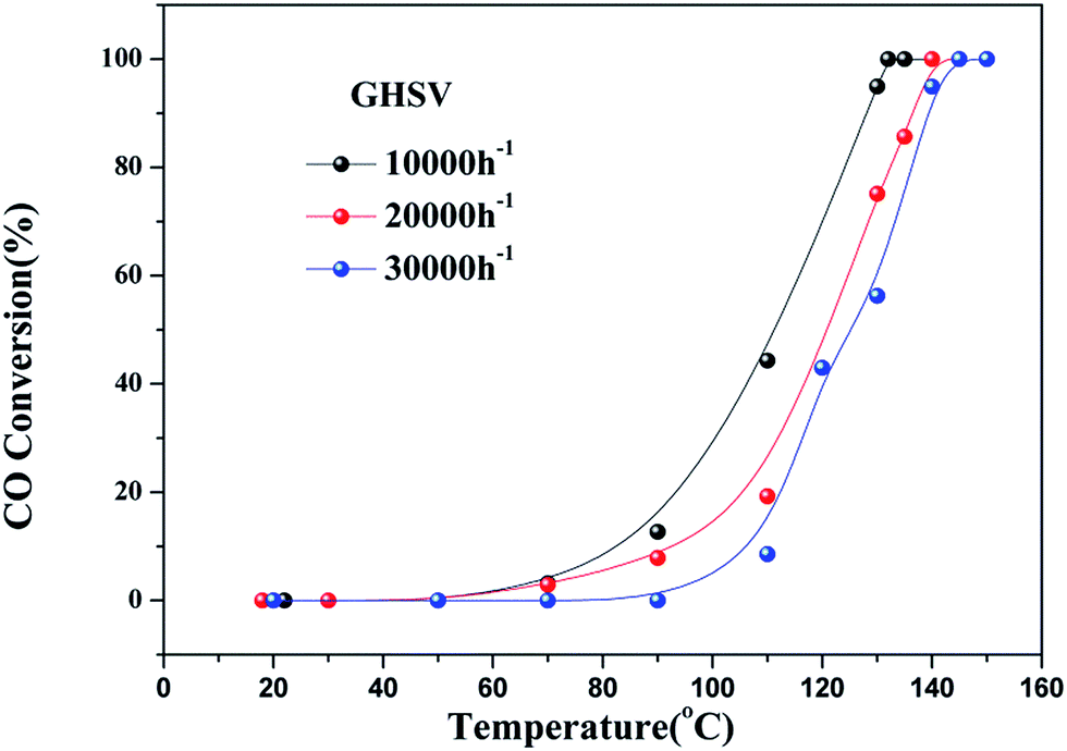
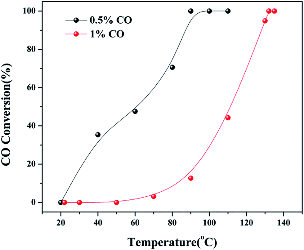
As observed in Fig. S2,† the three catalysts had different apparent activation energies. The activation energies of three catalysts were as follow: 48.03 kJ mol−1 (4Cu4Ce/graphene) > 68.03 kJ mol−1 (5Cu3Ce/graphene) > 109.98 kJ mol−1 (3Cu5Ce/graphene). Generally, the change in apparent activation energy was not consistent with the change in the CO conversion rate. In view of the abovementioned analysis, the higher the proportion of surface active oxygen in the catalyst, the higher the content of Ce3+ and the higher the content of Cu+/Cu0, which are more favorable for CO catalytic oxidation. However, in the 3D Cu–Ce/graphene, the changes in the proportion of surface active oxygen were different from the changes in the content of Ce3+ and Cu+/Cu0. It might result in a difference in the activation energy of these catalysts. Consequently, Fig. 8 confirmed the effect of space velocity on the CO oxidation. In summary, CO conversion at 130 °C increased with a decrease in GHSV: 10000 (94.93%) > 20000 (75.13%) > 30000 (56.25%). The CO conversion rate was determined by changing the CO concentration, as shown in Fig. 9. When the CO concentration changed to 0.5%, the whole process of the reaction was accelerated, and the complete conversion temperature was only 90 °C. This indicated that the 5Cu3Ce/graphene-catalyzed CO oxidation reaction should have a negative order.30 In other words, the decrease in CO concentration would promote the reaction process.
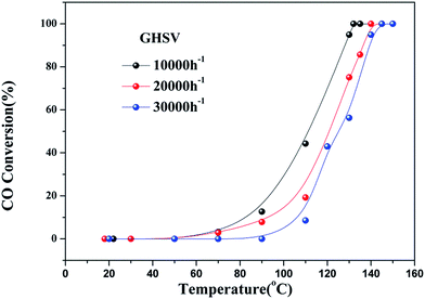 |
| | Fig. 8 CO conversion at different GHSV (10000, 20000, and 30000 h−1) over 5Cu3Ce/graphene in the CO oxidation reaction. | |
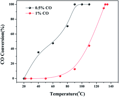 |
| | Fig. 9 CO conversion at different CO concentration (0.5 and 1%) over 5Cu3Ce/graphene in the CO oxidation reaction. | |
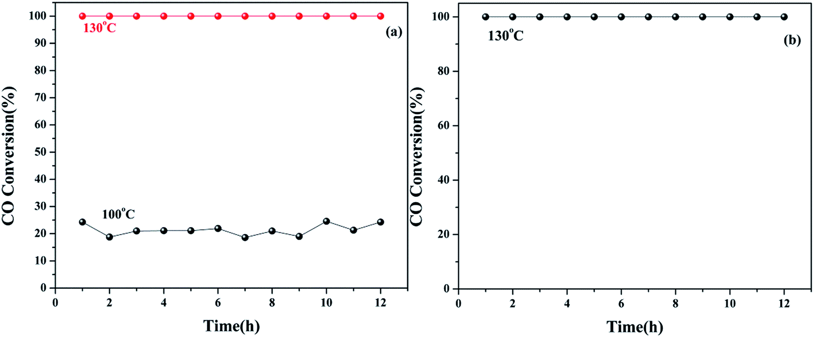
Furthermore, we investigated the long-term stability of the 5Cu3Ce/graphene catalyst and its stability in moisture. As shown in Fig. 10a, at the reaction temperature of 100 °C, the conversion of CO was about 24%. When the temperature was maintained at 100 °C in the reaction process, the conversion rate was stable, and CO conversion remained at about 24%. When the temperature was increased to 132 °C, the conversion rate still remained at 100%. Taking into account the negative impact of moisture on the CO oxidation reaction, we tested the Cu–Ce/graphene catalyst stability under the conditions of moisture at 132 °C. According to Fig. 10b, it could be seen that 100% conversion of CO could be retained at 132 °C, and after 12 h, it remained stable. This indicated that the 5Cu3Ce/graphene catalyst had great thermal stability and hydrothermal stability.
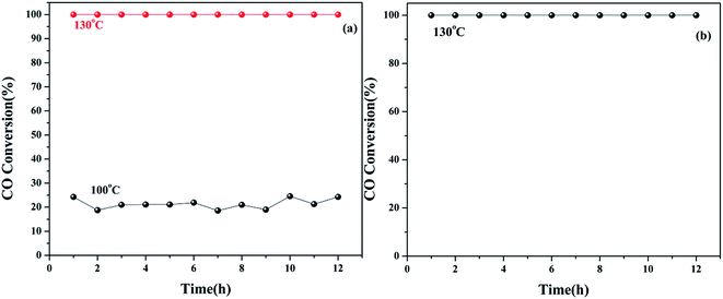 |
| | Fig. 10 (a) Time-dependent CO oxidation over the 5Cu3Ce/graphene catalyst. Reaction conditions: 1% CO balance air, WHSV = 10000 ml h−1 g−1. (b) The effect of moisture on CO oxidation over the 5Cu3Ce/graphene catalyst. Reaction conditions: under moisture and 1% CO balance air, WHSV = 10000 ml h−1 g−1. | |
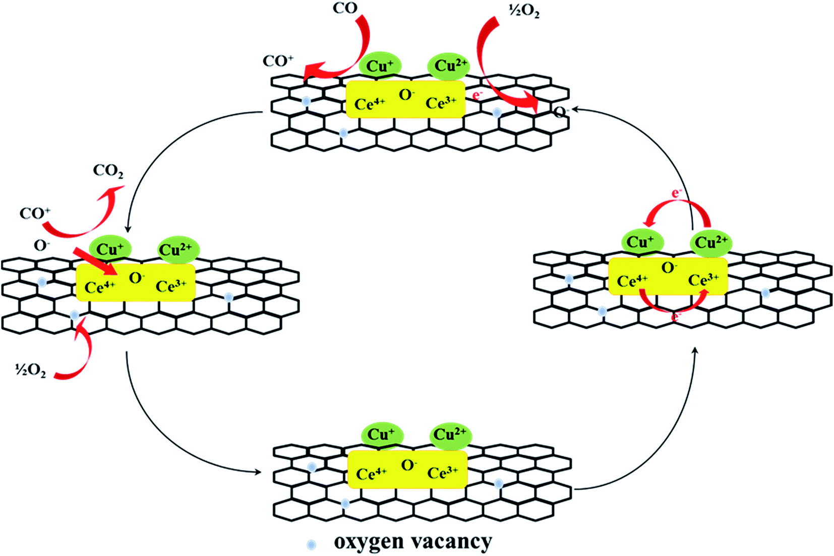
3.3 Reaction mechanism
The CO catalytic oxidation pathway was proposed, as shown in the Fig. 11.31,32 CO could react with the adsorbed oxygen species or active lattice oxygen on graphene and active component. The reaction pathways for CO oxidation included the surface reactions at the Cu–Ce interface, where CO was adsorbed onto metallic copper and reacted with the nearby adsorbed reactive oxygen species. The defective sites and oxygen-containing functional groups on graphene could activate O2 at the interface around the copper particles. The activated superoxide ions (O2−) or the lattice oxygen from cerium oxide produced at the Cu–Ce interface could react with the adsorbed CO to form CO2. The activation of the interface played a decisive role, and Cu+ effectively adsorbed CO and CeO2 as the interface of the oxygen molecular dissociation center. The oxygen vacancy near the copper species could accept oxygen from the volume diffusion of the lattice oxygen or gaseous oxygen once the surface oxygen was consumed. The electron transformation of the redox pair Cu2+/Cu+ and Ce4+/Ce3+ could promote the activation of lattice oxygen near the copper material. Moreover, during the reaction, the trace of water from air increased the composition of the surface active oxygen. According to the XPS analysis, the Ce4+ species changed to Ce3+ by lose of lattice oxygen in the reaction; this could promote the conversion of CO.
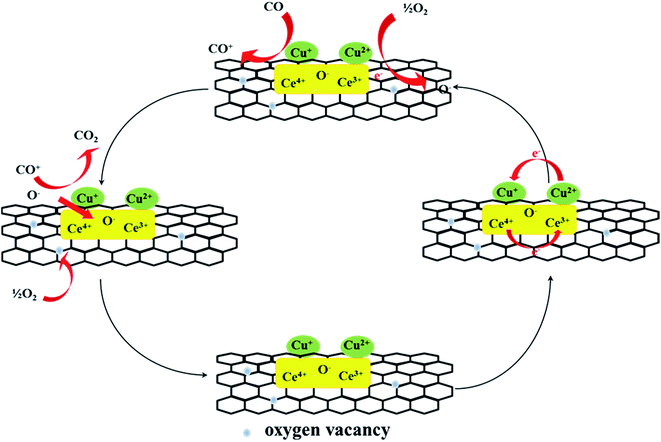 |
| | Fig. 11 The patterns of CO oxidation reaction mechanism over the surface of graphene. | |
3.4 Properties of the spent catalysts
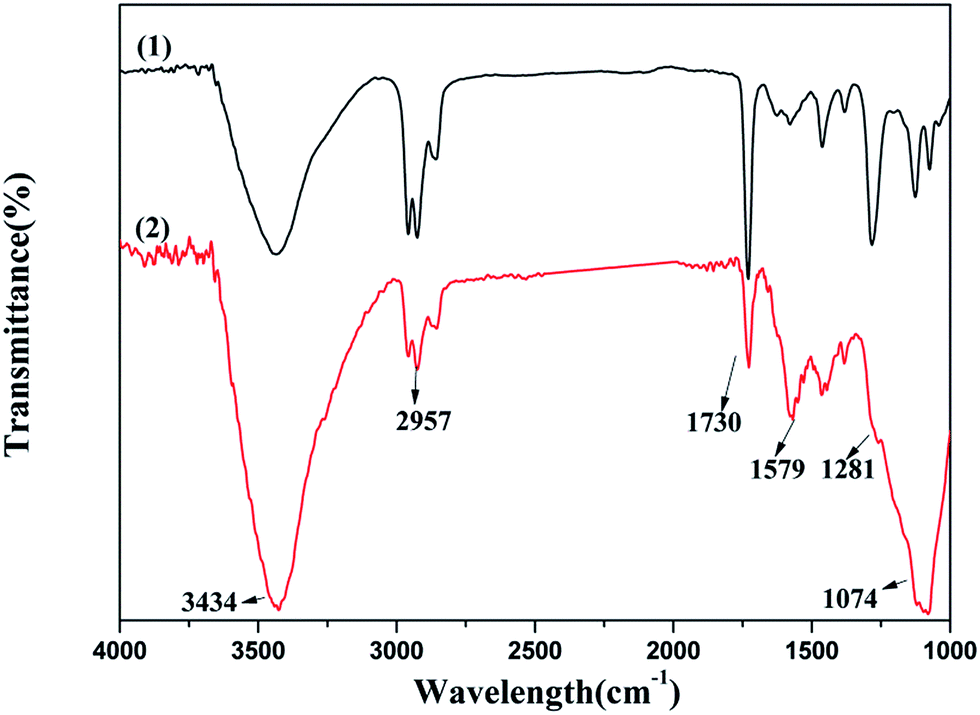
3.4.1 FTIR spectroscopy. The FTIR spectra of fresh 5Cu3Ce/graphene and used 5Cu3Ce/graphene composites are shown in Fig. 12. From Fig. 12, we could see that after the hydrothermal stability test, the absorption bands of O–H, CC, and C–O band at 3434, 1579, and 1074 cm−1 were strengthened, and the other bands of C–H, CO, and C–OH band at 2957, 1730, and 1281 cm−1 became weak after the reaction. The water added to the reaction system altered the content of O–H on the surface of graphene and generated the C–O and CC bonds to enhance the oxygen defected site in the graphene layer; the CO and C–OH bonds could provide an active oxygen species to promote the oxidation of CO. Both the active oxygen species and oxygen defected site promoted the progress of the reaction.
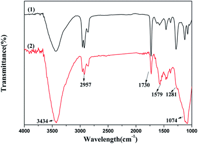 |
| | Fig. 12 FTIR spectra over the fresh 5Cu3Ce/graphene (1) and spent 5Cu3Ce/graphene (2) catalysts. | |
3.4.2 XPS analysis. The surface compositions and elemental states of the used 5Cu3Ce/graphene sample after 12 h hydrothermal stability test were examined by XPS, as shown in Fig. 13. Tables 2 and S1† provide the data on O, Cu, and Ce on catalysts analyzed before and after the reaction. With the progress of the reaction, the content of Oα, Oβ, and Cu2+ was decreased, whereas the content of Oγ and Ce3+ gradually increased. This result was consistent with the FTIR spectroscopy results. The increase in Ce3+ might be due to the reduction of Ce4+ at graphene during the reaction. As can be observed from the equation: Ce3+ + Cu2+ ↔ Ce4+ + Cu+/Cu0, the increase in Ce3+ and Cu+/Cu0 promotes the redox reaction cycle, which is beneficial for accelerating the conversion of CO oxidation. In addition, the rich adsorbed oxygen of the catalyst surface could promote CO oxidation. Therefore, although the content of surface active oxygen reduced, the catalyst still had superior catalytic activity and long-term stability.
 |
| | Fig. 13 O 1s Cu 2p and Ce 3d XPS spectra of the 5Cu3Ce/graphene (1) and spent 5Cu3Ce/graphene (2) catalysts. | |
4. Conclusions
In summary, experiments were conducted by modulating the molar ratio of Cu/Ce to regulate the number of active species and also to control the number of oxygen-containing functional groups on the surface of the graphene. Single metal-supported catalysts, such as Cu/graphene and Ce/graphene, showed very poor activity, whereas the bimetallic supported catalysts, such as 3Cu5Ce/graphene, 4Cu4Ce/graphene, and 5Cu3Ce/graphene, exhibited excellent activity. As the ratio of Cu/Cu was increased, the catalytic activity enhanced. Especially, the 5Cu3Ce/graphene catalyst showed a highest catalytic activity for CO oxidation, and the T100 value was 132 °C. The calcination of the apparent activation energy also verified the outstanding activity of the 5Cu3Ce/graphene catalyst, and the apparent activation energy was 68.03 kJ mol−1. Furthermore, the stability of the 5Cu3Ce/graphene catalyst was also good, which could be maintained for at least 12 h. The XRD analysis showed that the CeO2 particles were highly crystalline with size 5–9 nm, and the CuO nanoparticles were highly dispersed on CeO2 and graphene. With the enhancement of the Cu/Ce molar ratio in these catalysts, the number of oxygen-containing groups and active species was increased. According to the analysis, the interaction between the Ce species and graphene was stronger, and the Cu species were more easily reduced to expose more active sites and promote the conversion of CO. With the progress of the reaction, the surface adsorbed oxygen gradually decreased, but the oxygen defected site and the content of Ce3+ and Cu+/Cu0 increased. In line with the equation: Ce3+ + Cu2+ ↔ Ce4+ + Cu+/Cu0, this change was beneficial for promoting the oxidation of CO.
Conflicts of interest
There are no conflicts to declare.
Acknowledgements
The financial support provided by the National Natural Science Foundation of China (21407154, 21507137) and West Light Foundation of The Chinese Academy of Sciences is gratefully acknowledged.
References
- M. Luo, Y. Song, J. Lu, X. Wang and Z. Pu, J. Phys. Chem. C, 2007, 111, 12686–12692 CAS.
- A. Hornés, B. Hungría, P. Bera, L. Cámara, M. Fernández-García, A. Martínez-Arias, L. Barrio, M. Estrella, G. Zhou, J. J. Fonseca, J. C. Hanson and J. A. Rodriguez, J. Am. Chem. Soc., 2010, 132, 34–35 CrossRef PubMed.
- D. Gu, C. Jia, H. Bongard, B. Spliethoff, C. Weidenthaler, W. Schmidt and F. Schüth, Appl. Catal., B, 2014, 152–153, 11–18 CrossRef CAS.
- Y. Li, Y. Cai, X. Xing, N. Chen, D. Deng and Y. Wang, Anal. Methods, 2015, 7, 3238–3245 RSC.
- Z. Wu, H. Zhu, Z. Qin, H. Wang, J. Ding, L. Huang and J. Wang, Fuel, 2013, 104, 41–45 CrossRef CAS.
- C. Tang, J. Sun, X. Yao, Y. Cao, L. Liu, C. Ge, F. Gao and L. Dong, Appl. Catal., B, 2014, 146, 201–212 CrossRef CAS.
- G. Águila, F. Gracia and P. Araya, Appl. Catal., A, 2008, 343, 16–24 CrossRef.
- X. Chen, G. Wu, J. Chen, X. Chen, Z. Xie and X. Wang, J. Am. Chem. Soc., 2011, 133, 3693–3695 CrossRef CAS PubMed.
- R. Nie, J. Shi, S. Xia, L. Shen, P. Chen, Z. Hou and F. Xiao, J. Mater. Chem., 2012, 22, 18115–18118 RSC.
- R. Nie, J. Shi, W. Du, W. Ning, Z. Hou and F. Xiao, J. Mater. Chem. A, 2013, 1, 9037–9045 CAS.
- Y. Li, Y. Yu, J. Wang, J. Song, Q. Li, M. Dong and C. Liu, Appl. Catal., B, 2012, 125, 189–196 CrossRef CAS.
- F. Dong, Y. Zhao, W. Han, H. Zhao, G. Lu and Z. Tang, J. Mol. Catal., 2017, 439, 118–127 CrossRef CAS.
- M. Fernández-García, A. Martínez-Arias, A. Iglesias-Juez, C. Belver, A. B. Hungría, J. C. Conesa and J. Soria, J. Catal., 2000, 194, 385–392 CrossRef.
- J. Li, Y. Han, Y. Zhu and R. Zhou, Appl. Catal., B, 2011, 108–109, 72–80 CAS.
- Z. Wu, M. Li, J. Howe, H. M. Meyer III and S. H. Overbury, Langmuir, 2010, 26, 16595–16606 CrossRef CAS PubMed.
- N. Hoshyar, A. Irankhah and M. Jafari, Iranian Journal of Chemical Engineering, 2015, 12, 3–11 Search PubMed.
- Y. Yang, L. Jia, Y. Meng, B. Hou, D. Li and Y. Sun, Catal. Lett., 2012, 142, 195–204 CrossRef CAS.
- Q. Chen, L. Zhang and G. Chen, Anal. Chem., 2012, 84, 171–178 CrossRef CAS PubMed.
- M. Losurdo, M. Giangregorio, P. Capezzuto and G. Bruno, Phys. Chem. Chem. Phys., 2011, 13, 20836–20843 RSC.
- L. Qi, Q. Yu, Y. Dai, C. J. Tang, L. J. Liu, H. L. Zhang, F. Gao, L. Dong and Y. Chen, Appl. Catal., B, 2012, 119–120, 308–320 CrossRef CAS.
- W. Han, G. Zhang, G. Lu and Z. Tang, RSC Adv., 2015, 5, 59666–59676 RSC.
- G. Zhou, B. Dai, H. Xie, G. Zhang, K. Xiong and X. Zheng, J. CO2 Util., 2017, 21, 292–301 CrossRef CAS.
- N. Khan, C. Kim and S. Jhung, Chem. Eng. J., 2017, 311, 20–27 CrossRef CAS.
- C. Chen, Y. Zheng, Y. Zhan, X. Lin, Q. Zheng and K. Wei, Cryst. Growth Des., 2008, 8, 3549–3554 CAS.
- X. Gong, B. Liu, B. Kang, G. Xu, Q. Wang, C. Jia and J. Zhang, J. Mol. Catal., 2017, 436, 90–99 CrossRef CAS.
- Z. Xia, H. Liu, H. Lu, Z. Zhang and Y. Chen, Catal. Lett., 2017, 147, 1295–1302 CrossRef.
- R. Ramos, A. Grigoropoulos, N. Perret, M. Zanella, A. P. Katsoulidis, T. D. Manning, J. B. Claridge and M. J. Rosseinsky, Green Chem., 2017, 19, 1701–1713 RSC.
- C. Norsic, J. Tatibouët, C. B. Dupeyrat and E. Fourré, Chem. Eng. J., 2016, 304, 563–572 CrossRef CAS.
- C. Zhang, W. Lv, Q. Yang and Y. Liu, Appl. Surf. Sci., 2012, 258, 7795–7800 CrossRef CAS.
- Y. Li, Y. Yu, J. Wang, J. Song, Q. Li, M. Dong and C. Liu, Appl. Catal., B, 2012, 125, 189–196 CrossRef CAS.
- L. Li, W. Han, J. Zhang, G. Lu and Z. Tang, Microporous Mesoporous Mater., 2016, 231, 9–20 CrossRef CAS.
- X. Guo and R. Zhou, J. Power Sources, 2017, 361, 39–53 CrossRef CAS.
Footnote |
| † Electronic supplementary information (ESI) available. See DOI: 10.1039/c7ra11676d |
|
| This journal is © The Royal Society of Chemistry 2018 |
Click here to see how this site uses Cookies. View our privacy policy here. 
 Open Access Article
 This Open Access Article is licensed under a Creative Commons Attribution-Non Commercial 3.0 Unported Licence
 a,
Weiliang Hana,
Haijun Zhaoa and
Zhicheng Tang
a,
Weiliang Hana,
Haijun Zhaoa and
Zhicheng Tang