 Open Access Article
Self-assembled layer-by-layer partially reduced graphene oxide–sulfur composites as lithium–sulfur battery cathodes†
Cen Yaoa,
Yu Suna,
Kaisen Zhaoa,
Tong Wua,
Alain Maugerb,
Christian M. Julienb,
Lina Conga,
Jia Liua,
Haiming Xie *a and
Liqun Sun*a
aNational & Local United Engineering Laboratory for Power Battery, Northeast Normal University, Changchun 130024, PR China. E-mail: xiehm136@nenu.edu.cn
bSorbonne University, UPMC University Paris 06, Institut de Minéralogie, de Physique des Matériaux et de Cosmochimie (IMPMC), CNRS UMR 7590, 4 Place Jussieu, 75005 Paris, France
First published on 17th January 2018
Abstract
Constructing a reliable conductive carbon matrix is essential for the sulfur-containing cathode materials of lithium–sulfur batteries. A ready-made conductive matrix infiltrated with sulfur as the cathode is the usual solution. Here, a partially reduced graphene oxide–sulfur composite (prGO/S) with an ordered self-assembled layer-by-layer structure is introduced as a Li–S battery cathode. The prGO/S composites are synthesized through a facile one-step self-assembly liquid route. An appropriate amount of sulfur is in situ deposited on the surface of the prGO nanosheets by adjusting the reduction degree of the GO nanosheets. The combined effect of the electrostatic repulsions and surface energy makes the sulfur wrapped prGO nanosheets self-assemble to form an ordered layer-by-layer structure, which not only ensures the uniform distribution of sulfur but also accommodates the volume change of the sulfur species during cycling. Moreover, the conductivity of the prGO/S composites improves when the reduction time increases. XPS spectra confirm that sulfur is still chemically bonded to the prGO. After applying the prGO coating of the prGO/S composite particle and as an interlayer in a lithium–sulfur battery configuration, a high initial discharge capacity of 1275.8 mA h g−1 is achieved and the discharge capacity of the 100th cycle is 1013.8 mA h g−1 at 0.1C rate.
Introduction
Lithium–sulfur (Li–S) batteries are promising power sources to meet the requirement of high energy lithium ion batteries due to their high theoretical energy density of 2600 W h kg−1 and theoretical capacity of 1675 mA h g−1.1,2 However, the current Li–S batteries are still hindered by many unfavorable factors of the sulfur electrode, such as the low ionic and electronic conductivity of sulfur, the soluble intermediate Li polysulfides and the irreversible lithium sulfide by-products, which will greatly lower the utilization of active materials, causing low coulombic efficiency and short cycle life.3–5 Moreover, the large volume change of the sulfur electrode also results in low cycle stability during the charge–discharge reaction.To address these problems, many approaches have been reported in the literature, including the morphology optimization of host materials and the design of the whole electrode or cell structures. Carbon materials are the most common host materials, such as CMK-3 mesoporous carbon,6 activated carbon,7 porous carbon nanofiber,8 microporous carbon,9 graphene,10 etc., which were used both as the conductive matrix and as adsorptive carrier of sulfur, and can also accommodate the volume expansion effectively due to their special morphologies and structures. To alleviate the internal shuttle effect, many methods have been proposed, including the modification of cathode materials, separators and the whole structures of sulfur composite electrodes. Many kinds of coating materials were adopted, such as PEDOT:PSS,11 polyaniline,12 polydopamine,13,14 PPY,15 graphene oxide16 and TiO2.17 An interlayer stand between cathode area and traditional polymer separator effectively restricts the soluble intermediate polysulfides shuttling to the anode. This cell configuration in Li–S battery is an additional protection of the sulfur-contained cathode. Various conductive materials employed in Li–S battery cathode can be shaped like a separator or attached to one side of the separator as an interlayer, such as nickel foam,18 porous carbon nanofiber paper,19 TiO2–graphene,20 tungsten disulfide catalysts supported on a carbon cloth,21 reduced graphene oxide film22 and high-flux graphene oxide membrane.23
Graphene oxide (GO) with the unique 2D geometry has been used as a host material for Li–S batteries due to its ultrathinness, flexibility and high surface area compared to other conductive carbon or carbon nanotubes.24 The abundant functional groups on the GO surface would indeed facilitate the deposition of sulfur, which has been reported in many literatures.25–27 Considering the low electronic conductivity of the pristine GO, it is necessary to combine GO with some conductive materials or to synthesize partial reduced GO (prGO) to improve the electronic conductivity of the electrode. This is also the key factor for Li–S batteries since the sulfur exhibits intrinsic low electrical conductivity.28–30
In this work, we synthesized in situ partially reduced graphene oxide–sulfur (prGO/S) composites with a self-assembled layer-by-layer structure by a facile one-step liquid method. PrGO nanosheets with less functional groups and high electrical conductivity were obtained and used as the optimized carrier for sulfur. The residual functional groups keep the prGO nanosheets well dispersed in water,31 capture the sulfur atoms produced in the reaction solution and store them between the prGO nanosheets simultaneously. Thus, a regular and uniform multi-layer stacked structure of prGO/S forms in the process. XPS spectra confirm that the sulfur is still chemically bonded to the prGO. The prGO/S stacked structures were formed at different degrees of reduction by controlling the reaction time, and we report the effect of this parameter on the electrochemical performances of the prGO/S composites. Taking advantage of the presence of functional groups and the relatively high conductivity, we also used this prGO to coat composite particles and extended the process to the interlayer of Li–S battery configuration.
Experimental section
Partially reduced graphene oxide synthesis
Graphite oxide was prepared following a method reported in ref. 32. 100 mg of graphite oxide was dispersed in 200 mL ultrapure water (18 MΩ), then sonicated for 2 hours to form a stable colloid in water. 51 μL hydrazine hydrate and 10 μL ammonia were added into the GO dispersion, stirred for 30, 60, 120 min at 95 °C to obtain three different products, then centrifuged at 3500 rpm and washed with water and 30% HCl solution for several times. The products were dispersed in 200 mL ultrapure water and sonicated for 3 h to obtain the partially reduced graphene oxides named prGO-30, prGO-60, prGO-120, prGO-240, respectively.Self-assembled layer-by-layer structure prGO/S composites
1.86 g Na2S2O3 was dissolved into 400 mL water to form a uniform solution, which was mixed with 200 mL of the prGO dispersion liquid, then stirred for 15 min. Then 0.1 M HCl was added dropwise to the above solution, stirred overnight. The collected precipitate was washed with water and centrifuged at 3500 rpm for several times. The final product was dried at 50 °C in air over night, and noted as prGO-30/S, prGO-60/S, prGO-120/S, according to the prGO chosen. Pristine GO/S composite was obtained using pristine GO instead of prGO.The coating process
0.5 mg mL−1 prGO-60 dispersion was added to the 400 mL dispersion of prGO-120/S under stirring, and the resulting solution was stirred for 1 h. The precipitate was collected, washed with water by centrifuged at 3500 rpm for several times. The product was dried at 50 °C in air over night.Preparation of separator with prGO interlayer
0.5 mg mL−1 prGO-60 dispersion was centrifuged at 3500 rpm, and dump the supernatant than dispersed in ethanol. This suspension was sonicated for 1 h, and vacuum filtered through Celgard 2400 polymer separator. The areal density of prGO is around 0.2 mg cm−2.38 The separator combined with the prGO interlayer was dried at 50 °C in air over night.Materials characterization
Powder X-ray diffraction (XRD) spectra were recorded on a Rigaku D/max 2000 spectrometer using Cu Kα radiation (λ = 1.5406 Å) over the 2θ range of 5–80°. The morphology of the composites was observed with a scanning electron microscope (SEM, Philips XL30, operating at 10 kV) with an energy dispersive X-ray spectrometer (EDS). Transmission electron microscopy (TEM) was carried out on a Hitachi HD-2000 STEM. The sulfur content in the composites was measured by using a TG/DTA 6300 in an N2 flow to obtain the sulfur content in the composite. Infrared spectra were recorded using a Fourier transform infrared (FTIR) spectrometer (Nicolet 6700-FTIR). Raman spectrum was obtained on a JY HR-800 system. XPS measurements were performed on a PHI5500 system.Electrochemical measurements
The electrochemical performance of the prGO/S composite cathodes was investigated in coin-type cells (CR2025). The cathode slurry was prepared by mixing 80 wt% of the prGO/S composite, 10 wt% of the pvdf binder, and 10 wt% of the carbon black conductive agents in an N-methyl-pyrrolidone dispersant to form homogeneous slurry. The resulting slurry was uniformly coated on an aluminum foil current collector and dried at 50 °C for 24 h in a vacuum oven. The prGO/S cathode had a diameter of 13 mm and the sulfur loading was approximately 1.0–1.5 mg cm−2. The coin-type cells were assembled in an argon-filled glove box by using a Celgard 2400 or the Celgard 2400 combined with the prGO interlayer as separator and lithium foil as the anode. The electrolyte was 1 M lithium bis(trifluoromethane) sulfonamide (LiTFSI) in 1,3-dioxolane/dimethoxymethane (DOL/DME, 1![[thin space (1/6-em)]](https://www.rsc.org/images/entities/char_2009.gif) :
:![[thin space (1/6-em)]](https://www.rsc.org/images/entities/char_2009.gif) 1 by volume) with 0.1 M LiNO3 additive. The cells were cycled in the voltage range 1.7–2.8 V. The cyclic voltammograms (CV) of the batteries were measured on a Princeton PARSTAT 4000 electrochemical workstation from 1.7 to 3 V at a scan rate of 0.1 mV s−1. The electrochemical impedance spectroscopy tests were carried out at room temperature using a Princeton PARSTAT 4000 Electrochemistry Workstation in a range of 0.1 Hz to 100 kHz. The cathodes were adopted as the work electrode; the counter electrode and reference electrode were Li foil.
1 by volume) with 0.1 M LiNO3 additive. The cells were cycled in the voltage range 1.7–2.8 V. The cyclic voltammograms (CV) of the batteries were measured on a Princeton PARSTAT 4000 electrochemical workstation from 1.7 to 3 V at a scan rate of 0.1 mV s−1. The electrochemical impedance spectroscopy tests were carried out at room temperature using a Princeton PARSTAT 4000 Electrochemistry Workstation in a range of 0.1 Hz to 100 kHz. The cathodes were adopted as the work electrode; the counter electrode and reference electrode were Li foil.
Results and discussion
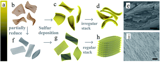
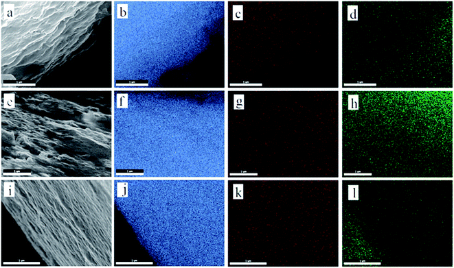
The structure of GO and prGO is similar to that of graphene, which is a single atomic layer of sp2-bonded carbon atoms.32 However, GO is electrically insulating, and can be reduced to conducting prGO.31 The color will gradually change from golden yellow (GO) to pure black (rGO) (Fig. 1a) as the chemical reduction progress. Fig. 1b and f–h illustrate the general procedures for the synthesis of the self-assembled layer-by-layer prGO/S composites. In the first step, graphite oxide was dissolved in ultrapure water and sonicated to get an homogeneous graphene oxide dispersion (Fig. 1b). In the second step, the graphene oxide dispersion was reduced under various controlled conditions to get the homogeneous partially reduced graphene oxide dispersion, as illustrated in Fig. 1f.31 In the final step, sulfur was incorporated through in situ reaction deposit on both sides of the prGO nanosheets to get the sulfur wrapped prGO nanosheets. After sulfur wrapping, the functional groups on prGO nanosheets were covered by the sulfur layer. These sulfur-wrapped prGO nanosheets are no longer negatively charged and stack to each other (see Fig. 1g–i). The pristine GO sheets after addition of sulfur exhibit a large interlayer distance and a rippled structure (Fig. 1c and d). Due to the numerous inorganic functional groups with highly negative charge on the surface of GO nanosheets, the sulfur layer deposited on the GO surface was thicker, resulting in the irregular and random arrangement of GO/S composites (Fig. 1e). The features of prGO/S enable a uniform distribution of the sulfur, thus avoiding any agglomeration of sulfur particles, which can accommodate the volume change of S-species during while cycling. Although the functional groups of prGO nanosheets decrease, the electronic conductivity increases obviously.33,34 Meanwhile, the ripples induced by the functional groups and the electrostatic repulsion among prGO/S sheets were all weakened, so that the prGO/S sheets were relatively flat, a feature that permitted the formation in situ of the regular and uniform layer-by-layer stacking structure of prGO/S sheets (Fig. 1h and i). This tightly packed layer-by-layer structure serves as a good conducting matrix that isolates sulfur and Li2S, prevents aggregation, and accommodates the volume change of sulfur during cycling. The resulting improvement of the prGO-120/S composite as a cathode, evidenced in the next section is thus due to this tightly packed layer-by-layer morphology.The prGO/S composites prepared at different reduction times (prGO-30/S, prGO-60/S, prGO-120/S) were explored systematically by SEM and the EDS analysis, as shown in Fig. 2. The images in Fig. 2a, e and i show no block and large particles of sulfur appeared on the surface or interlayer of the prGO sheets. Since the reduction time of prGO-30/S and prGO-60/S is both not long, their morphology is similar. As indicated in Fig. 2, the layer thickness of prGO-30/S is larger than that of prGO-60/S, so the prGO-30/S is more difficult to form the order layer-by-layer structure. The layer-by-layer stacking structure becomes more and more ordered with increasing of reduction degree. This is confirmed by the TEM images (Fig. 4) showing morphologies that shift from irregular and random for GO/S (Fig. 4a) to the regular and planar stacking layer of prGO/S (Fig. 4d) as the reduction time increased. The EDS analysis (Fig. 2) revealed that the S, O and C elements are distributed homogeneously not only on the surface but also among interlayer of prGO sheets in three composites.
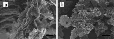
To confirm the structural changes of prGO/S after longer reduction time, prGO-240/S composites were also synthesized by reducing GO during 240 min. The prGO-240 sheets were much thinner (Fig. 3a) due to the large decrease of the surface functional groups. Moreover, the prGO-240 has failed to distribute the sulfur atoms forming in the aqueous solution due to the tightly stacking structure of prGO-240 with insufficient functional groups to weakly adsorb the sulfur atoms. The consequence is the agglomeration of sulfur and formation of sulfur spherical particles on the surface of prGO-240 (Fig. 3b). Thus, the unique layer-by-layer prGO-30/S, prGO-60/S, prGO-120/S composites have sulfur only into the interlayer, with a tuned amount of sulfur deposition, avoiding the agglomeration of sulfur particles. When the reduction is too strong, however, this is no longer the case, and this is illustrated by the prGO-240/S composite.
TEM images in Fig. 4 show the layer-by-layer morphologies of prGO/S composites more clearly. GO/S (Fig. 4a) and prGO-30/S (Fig. 4b) exhibit irregular non-layer structure due to more functional groups on the surface and interlayer, while prGO-60/S (Fig. 4c) has the layer-by-layer structure, even though its interlayer is still not perfectly shaped. PrGO-120/S (Fig. 4d) has the best and regular layer-by-layer stacking structure with smooth interlayer morphology, which matches with the SEM images. This morphology is different from that of graphite, graphite oxide, and graphene. In this unique structure, the prGO wrapped with sulfur on both sides, and then self-assembled to reach a stable state by decreasing surface energy.
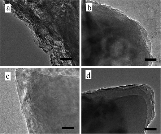 | ||
| Fig. 4 TEM images of pristine GO/S (a), prGO-30/S (b), prGO-60/S (c) and prGO-120/S (d) composite. Scale bar, 50 nm. | ||
According to the thermogravimetric analysis (TGA), the sulfur content in prGO-120/S, prGO-60/S, prGO-30/S and pristine GO/S composite is 74.2 wt%, 78.7 wt%, 80.3 wt% and 82.8 wt%, respectively (Fig. 5a). The weight ratio of sulfur to GO decreases from 4.81 for GO/S composite to 4.08, 3.69 and 2.88 for prGO-30/S, prGO-60/S and prGO-120/S, respectively. This means a decreasing ratio of 15.2%, 23.3%, and 40.1% (see Table 1) compared with GO/S. The amount of sulfur deposition in prGO-120/S composite is smaller than that of the other composites, which agrees well with the results of the previous sections attributed to the decrease of functional groups weakening the bonding of sulfur and the prGO. It also can be seen from XRD patterns in Fig. 5b that the prGO-120/S composite shows the lowest peak intensity, due to the lower sulfur content.
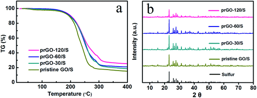 | ||
| Fig. 5 (a) TG curve of pristine GO/S, prGO-30/S, prGO-60/S and prGO-120/S composite from 25 to 400 °C. (b) XRD pattern of sulfur, pristine GO/S, prGO-30/S, prGO-60/S and prGO-120/S composite. | ||
| Samples | Sulfur content (wt%) | Weight ratio of sulfur to prGO | Weight ratio decrease compared to GO/S (%) |
|---|---|---|---|
| prGO-120/S | 74.2 | 2.88 | 40.1 |
| prGO-60/S | 78.7 | 3.69 | 23.3 |
| prGO-30/S | 80.3 | 4.08 | 15.2 |
| Pristine GO/S | 82.8 | 4.81 | 0 |
The reaction mechanism and the changes of functional groups of prGO/S composites were investigated by FTIR and Raman spectroscopy (Fig. 6a). The IR spectra of pristine GO/S composite are basically consistent to that of pristine GO, since the sulfur deposition does not change the functional groups on GO. After partial reduction, the O–H stretching vibration at 3420 cm−1 decreases importantly, even for reduction time as small as 30 min. The intensity of C![[double bond, length as m-dash]](https://www.rsc.org/images/entities/char_e001.gif) O stretching vibration at 1740 cm−1 and the C–O stretching vibration at 1250 cm−1 also decrease upon increasing the reduction time, but the C–O stretching vibration is still observed clearly for a reduction time of 120 min, which means that the main functional groups are the C–O rather than the C
O stretching vibration at 1740 cm−1 and the C–O stretching vibration at 1250 cm−1 also decrease upon increasing the reduction time, but the C–O stretching vibration is still observed clearly for a reduction time of 120 min, which means that the main functional groups are the C–O rather than the C![[double bond, length as m-dash]](https://www.rsc.org/images/entities/char_e001.gif) O groups in the prGO/S composites. The transmittance intensity of the unoxidized sp2 C
O groups in the prGO/S composites. The transmittance intensity of the unoxidized sp2 C![[double bond, length as m-dash]](https://www.rsc.org/images/entities/char_e001.gif) C bonds stretching vibration at 1620 cm−1 is unchanged, except for the lightly shift of the peak to lower wavenumber, which is also shown in Raman spectra (Fig. 6b). The G band (1596 cm−1) is assigned to the vibration of sp2-bonded carbon atoms and the D band (1330 cm−1) is assigned to the disorder or defects in carbon matrix. The ID/IG value increases gradually from 0.937 of GO/S to 1.049 of prGO-120/S with the reduction time extended (Table 2). It can be seen that the ID/IG ratio in prGO-120/S (1.049) is slight larger than that in prGO-60/S (1.041), which means the presence of a small quantity of hydroxyl and methylene groups in prGO destroys the re-graphitization of GO. Due to the presence of C sp3 atoms, the new created graphitic domains in rGO are more numerous in number, but is smaller in size than that present in GO. So, the average size of the sp2 domains in GO decrease after chemical reduction, thus lead to the increase appears in ID/IG ratio.36,37 Moreover, the new created graphitic domains formed many conductive pathways in prGO during reduction, which benefit for the increasing of the electronic conductivity of prGO-120/S.
C bonds stretching vibration at 1620 cm−1 is unchanged, except for the lightly shift of the peak to lower wavenumber, which is also shown in Raman spectra (Fig. 6b). The G band (1596 cm−1) is assigned to the vibration of sp2-bonded carbon atoms and the D band (1330 cm−1) is assigned to the disorder or defects in carbon matrix. The ID/IG value increases gradually from 0.937 of GO/S to 1.049 of prGO-120/S with the reduction time extended (Table 2). It can be seen that the ID/IG ratio in prGO-120/S (1.049) is slight larger than that in prGO-60/S (1.041), which means the presence of a small quantity of hydroxyl and methylene groups in prGO destroys the re-graphitization of GO. Due to the presence of C sp3 atoms, the new created graphitic domains in rGO are more numerous in number, but is smaller in size than that present in GO. So, the average size of the sp2 domains in GO decrease after chemical reduction, thus lead to the increase appears in ID/IG ratio.36,37 Moreover, the new created graphitic domains formed many conductive pathways in prGO during reduction, which benefit for the increasing of the electronic conductivity of prGO-120/S.
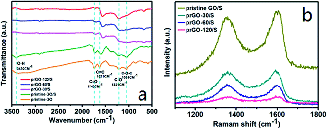 | ||
| Fig. 6 Infrared spectroscopy (a) and Raman spectra (b) of pristine GO/S, prGO-30/S, prGO-60/S and prGO-120/S composites. | ||
| Samples | Pristine GO/S | prGO-30/S | prGO-60/S | prGO-120/S |
| ID/IG value | 0.937 | 0.969 | 1.041 | 1.049 |
XPS was carried out to further analyze the chemical bonding of prGO/S composites as shown in Fig. 7. The S 2p spectrum of all samples (Fig. 7a, d, g and j) shows four sub-peaks located at 163.6 and 164.8 eV corresponding to S–S and C–S bond, 164.3 and 165.5 eV corresponding to O–S, indicating that the sulfur is chemically bonded to the reduced GO. After partial reduction, the peak associated to the C–S bond is decreased, which is attributable to the decreasing of the functional groups and sulfur loading in prGO-120/S composite. The other weak peak at 168.4 eV is attributed to the sulfate species formed by oxidation of sulfur in the air. Fig. 7b, e, h and k consist of the C 1s component peaks at 284.6, 285.6, 287.5 and 289.0 eV. The main peak at 284.6 eV corresponds to the C–C/C![[double bond, length as m-dash]](https://www.rsc.org/images/entities/char_e001.gif) C, and the peaks with higher binding energy at 285.6 and 287.5 eV are characteristic of C–O/C–S, C
C, and the peaks with higher binding energy at 285.6 and 287.5 eV are characteristic of C–O/C–S, C![[double bond, length as m-dash]](https://www.rsc.org/images/entities/char_e001.gif) O,35 giving further evidence that C incorporates, not simply mixes with sulfur in prGO/S composite. After partial reduction, the peaks intensities related to C
O,35 giving further evidence that C incorporates, not simply mixes with sulfur in prGO/S composite. After partial reduction, the peaks intensities related to C![[double bond, length as m-dash]](https://www.rsc.org/images/entities/char_e001.gif) O and O–C
O and O–C![[double bond, length as m-dash]](https://www.rsc.org/images/entities/char_e001.gif) O are reduced, implying that the oxygen-containing functional groups have been partially removed. The peak at 284.6 eV becomes sharp and narrow with the increase of the reduction time, further confirming the increasing degree of graphitization, corresponding to the Raman results. In the O 1s spectrum, the peak at 532.9 eV is assigned to C–OH/C–O–C groups (Fig. 7c, f, i and l). The peak at 531.8 eV is attributed to the S–O bond, indicating that sulfur contacts with graphene intimately through S–O bonding, which can immobilize sulfur and polysulfides during charge and discharge process, and hence favor to improve the cycle performance of the prGO/S electrode.28
O are reduced, implying that the oxygen-containing functional groups have been partially removed. The peak at 284.6 eV becomes sharp and narrow with the increase of the reduction time, further confirming the increasing degree of graphitization, corresponding to the Raman results. In the O 1s spectrum, the peak at 532.9 eV is assigned to C–OH/C–O–C groups (Fig. 7c, f, i and l). The peak at 531.8 eV is attributed to the S–O bond, indicating that sulfur contacts with graphene intimately through S–O bonding, which can immobilize sulfur and polysulfides during charge and discharge process, and hence favor to improve the cycle performance of the prGO/S electrode.28
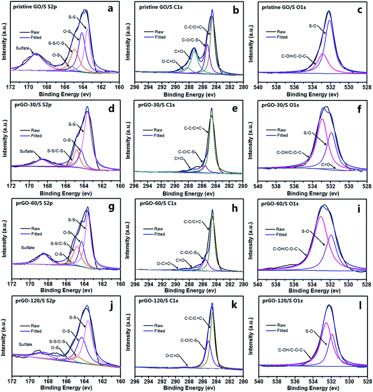 | ||
| Fig. 7 S 2p, C 1s and O 1s XPS spectra of pristine GO/S (a–c), prGO-30/S (d–f), prGO-60/S (g–i) and prGO-120/S (j–l) composites. | ||
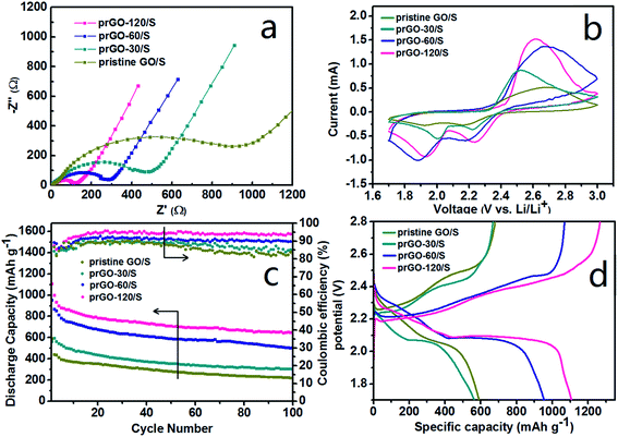
The superior electrochemical performance of prGO/S and pristine GO/S were analyzed systematically. All the impedance spectra (Fig. 8a) consist of a depressed semicircle in the high-medium frequency region followed by a slanted line in the low frequency region. The semicircle corresponds to the charge transfer resistance (Rct) at the electrode/electrolyte interface, and the straight line in the low-frequency domain corresponds to a semi-infinite Warburg diffusion process. All the cells with prGO/S composites as cathode show smaller high-frequency semicircle and lower serial resistance than pristine GO/S. Along with the reduction of prGO, the high-frequency semicircle is getting smaller and the charge-transfer resistance decreases dramatically to the lowest value (124 Ω) in the prGO-120/S, indicating a better electrochemical activity of prGO-120 served as the conductive carbon matrix of the cathode. The equivalent circuit used in the simulation of impedance spectra is illustrated in Fig. S1.† This result gives evidence that the conductivity of the composites was improved by the loss of functional groups on GO, which exhibits an inverse relationship between the amount of functional groups on prGO and the conductivity of prGO.
Cyclic voltammetry (CV) was used to characterize the electrochemical reaction mechanism of the cathode materials (Fig. 8b) between 1.7 and 3.0 V at a scan rate of 0.1 mV s−1. Two reduction peaks at 1.9–2 V and 2.2–2.3 V were observed, which are attributed to the reduction of sulfur to soluble lithium polysulfides (Li2Sx, 4 ≤ x ≤ 8) and the reduction of higher-order polysulphides to lower-order polysulphides (insoluble Li2Sx, 2 ≤ x ≤ 4). Fig. 8c shows the cycling performance and coulombic efficiency of the prGO/S composites electrode at 167.5 mA g−1 (0.1C) in the potential range of 1.7–2.8 V at room temperature. The current of discharge and charge is based on the mass and theoretical capacity of sulfur (1C = 1675 mA g−1). The initial specific capacity of pristine GO/S, prGO-30/S, prGO-60/S and prGO-120/S is 590.6, 564.1, 953.4 and 1107.1 mA h g−1, respectively. The discharge capacity increases with the reduction degree of prGO. After 100 cycles, the capacity retention of pristine GO/S, prGO-30/S, prGO-60/S and prGO-120/S is 50.1%, 50.6%, 58.7% and 64.7%, respectively. The capacity retention is calculated on the basis of discharge capacity data of the 100th cycle and the second cycle. Due to the presence of functional groups, all the prGO/S composites and the pristine GO/S composite exhibit a reduced capacity fading during charge–discharge cycling. Along with the reduction, the layer-by-layer stacked structure becomes more and more ordered, which also contributes to the capacity retention. During the first ten cycles, the generally improving coulombic efficiency just corresponds to the fast decay of the discharge specific capacity. After 50 cycles, the coulombic efficiency of prGO-30/S and prGO-60/S composites decrease due to the more irregular layer-by-layer structure compared with prGO-60/S and prGO-120/S composite. Fig. 8d presents initial charge–discharge profiles of the four simples. Although the layer-by-layer structure prGO/S composites could confine the sulfur within its particles, the sulfur attached to its outer surface is still exposed to the electrolyte and would dissolve out of cathode into electrolyte easily without any physical barriers.
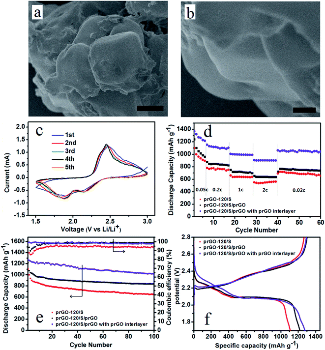
During charge and discharge process, the soluble intermediate Li polysulfides dissolve in the cathode electrolyte, diffuse through the separator and thus causing irreversible capacity loss. Coating of the cathode material can prevent the polysulfides diffusion, and an interlayer stand between cathode area and separator would also prevent this diffusion process. Thus improve the electrochemical performance of lithium–sulfur battery. Considering the surface and flank of the self-assembled layer-by-layer structure are still exposed in the electrolyte, prGO-coating prGO-120/S composite (prGO-120/S/prGO) was synthesized. Fig. 9a and b show that the surface of prGO-120/S/prGO composite becomes smooth, and the uniform layer-by-layer structure flank of prGO-120/S composite is wrapped by prGO completely, which can then be used to prevent the loss of the active materials arising from the surface sulfur of prGO-120/S composite dissolving into the electrolyte. The prGO-120/S/prGO composite delivers a high initial discharge capacity of 1218.1 mA h g−1 at 0.1C. After 100 cycles, its discharge capacity is 835.4 mA h g−1 and capacity retention is 77.8%, as shown in Fig. 9e. A separator with prGO interlayer is also used in assembling the cell with the prGO-120/S/prGO composite as cathode. The first five cycles of CVs of prGO-120/S/prGO composite cathode with prGO interlayer at 0.1 mV s−1 of 1.5–2.8 V (Fig. 9c) show good reversibility. Using the prGO interlayer, the initial discharge capacity rises to 1275.8 mA h g−1. After 100 cycles, its discharge capacity is 1013.8 mA h g−1 and capacity retention after 100 cycles is 80.5%, as shown in Fig. 9e. The coulombic efficiency of prGO-120/S/prGO with prGO interlayer, prGO-120/S/prGO and prGO-120/S composite is shown in Fig. 9e. After applying the prGO interlayer, the coulombic efficiency is around 99% from the first cycle indicating that the soluble intermediate polysulfides was prevented from shuttling to the anode. Fig. 9f presents the initial charge–discharge profiles of the three simples. Fig. 9d shows the specific capacities at various charge/discharge rates from 0.05C to 2C for prGO-120/S and prGO-120/S/prGO composite and prGO-120/S/prGO composite with prGO interlayer. The prGO-120/S/prGO cathode with prGO interlayer shows a high discharge capacity of 1370.1 mA h g−1 at 0.05C, which is 81.8% of the theoretical value (1675 mA h g−1), higher than that of the prGO-120/S cathode (1100.1 mA h g−1) and prGO-120/S/prGO (1239.8 mA h g−1). At a charge/discharge rate as high as 2C, it still maintains 906.7 mA h g−1, which is more than that of the prGO-120/S cathode (551.1 mA h g−1) and prGO-120/S/prGO cathode (655.2 mA h g−1). This capacity retention at various C rates could be attributed to the self-assembled layer-by-layer structure, coating with prGO and applying prGO as interlayer.
Conclusion
An optimized ordered layer-by-layer self-assembled prGO/S composite was in situ synthesized by a facile liquid method. The special layer-by-layer structure of prGO/S supplied a regular storage space for sulfur atoms, avoiding the agglomeration of sulfur and accommodating the volume changes during the electrochemical reaction. The chemical interaction between sulfur and the functional groups effectively restrains the sulfur shuttle and also confines polysulfides, preventing them from dissolving in the electrolyte. The prGO also acts as a conductive matrix to ensure the high conductivity of prGO/S composites. XPS spectra confirm that the sulfur is still chemically bonded to the prGO after partial reduction. As a result, the prGO-120/S composite cathodes display the highest specific capacity among the prGO/S composites. Since prGO could benefit from both the chemical binding of sulfur and the reinforcement of electrical conductivity, this prGO-120/S composite showed high specific capacity, cycle stability over 100 cycles, and better rate capability at 2C. This self-assembled layer-by-layer prGO/S composite can thus provide an effective clue in constructing more reliable conductive carbon matrix applied in Li–S battery cathode.Conflicts of interest
There are no conflicts to declare.Acknowledgements
This work was supported by Special Fund of Key Technology Research and Development Projects for Science and Technology Innovation of Power Batteries and Separators, Jilin province Science and Technology Department, “13th Five-year plan” Science and Technology Research of Jilin province, Key Subject Construction of Physical Chemistry of Northeast Normal University.References
- P. G. Bruce, S. A. Freunberger, L. J. Hardwick and J. M. Tarascon, Nat. Mater., 2012, 11, 19–29 CrossRef CAS PubMed.
- A. Manthiram, Y. Fu, S. H. Chung, C. Zu and Y. S. Su, Chem. Rev., 2014, 114, 11751–11787 CrossRef CAS PubMed.
- L. F. Nazar, M. Cuisinier and Q. Pang, MRS Bull., 2014, 39, 436–442 CrossRef CAS.
- Y. Yang, G. Zheng and Y. Cui, Chem. Soc. Rev., 2013, 42, 3018–3032 RSC.
- X. Zhang, H. M. Xie, C. S. Kim, K. Zaghib, A. Mauger and C. M. Julien, Mater. Sci. Eng., R, 2017, 121, 1–29 CrossRef.
- X. Ji, K. T. Lee and L. F. Nazar, Nat. Mater., 2009, 8, 500–506 CrossRef CAS PubMed.
- H. S. Ryu, J. W. Park, J. Park, J.-P. Ahn, K.-W. Kim, J.-H. Ahn, T.-H. Nam, G. Wang and H.-J. Ahn, J. Mater. Chem. A, 2013, 1, 1573 CAS.
- L. Ji, M. Rao, S. Aloni, L. Wang, E. J. Cairns and Y. Zhang, Energy Environ. Sci., 2011, 4, 5053 CAS.
- J. Xu, J. Shui, J. Wang, M. Wang, H.-K. Liu, S. X. Dou, I.-Y. Jeon, J.-M. Seo, J.-B. Baek and L. Dai, ACS Nano, 2014, 8, 10920–10930 CrossRef CAS PubMed.
- S. Zheng, F. Yi, Z. Li, Y. Zhu, Y. Xu, C. Luo, J. Yang and C. Wang, Adv. Funct. Mater., 2014, 24, 4156–4163 CrossRef CAS.
- Y. Yang, G. Yu, J. J. Cha, H. Wu, M. Vosgueritchian, Y. Yao, Z. Bao and Y. Cui, ACS Nano, 2011, 5, 9187–9193 CrossRef CAS PubMed.
- G.-C. Li, G.-R. Li, S.-H. Ye and X.-P. Gao, Adv. Energy Mater., 2012, 2, 1238–1245 CrossRef CAS.
- Y. Deng, H. Xu, Z. Bai, B. Huang, J. Su and G. Chen, J. Power Sources, 2015, 300, 386–394 CrossRef CAS.
- W. Zhou, X. Xiao, M. Cai and L. Yang, Nano Lett., 2014, 14, 5250–5256 CrossRef CAS PubMed.
- W. Li, Q. Zhang, G. Zheng, Z. W. Seh, H. Yao and Y. Cui, Nano Lett., 2013, 13, 5534–5540 CrossRef CAS PubMed.
- J. Rong, M. Ge, X. Fang and C. Zhou, Nano Lett., 2014, 14, 473–479 CrossRef CAS PubMed.
- Z. Wei Seh, W. Li, J. J. Cha, G. Zheng, Y. Yang, M. T. McDowell, P. C. Hsu and Y. Cui, Nat. Commun., 2013, 4, 1331 CrossRef PubMed.
- K. Zhang, F. Qin, J. Fang, Q. Li, M. Jia, Y. Lai, Z. Zhang and J. Li, J. Solid State Electrochem., 2013, 18, 1025–1029 CrossRef.
- J. Wang, Y. Yang and F. Kang, Electrochim. Acta, 2015, 168, 271–276 CrossRef CAS.
- Z. Xiao, Z. Yang, L. Wang, H. Nie, M. Zhong, Q. Lai, X. Xu, L. Zhang and S. Huang, Adv. Mater., 2015, 27, 2891–2898 CrossRef CAS PubMed.
- J. Park, B.-C. Yu, J. S. Park, J. W. Choi, C. Kim, Y.-E. Sung and J. B. Goodenough, Adv. Energy Mater., 2017, 7, 1602567 CrossRef.
- X. Wang, Z. Wang and L. Chen, J. Power Sources, 2013, 242, 65–69 CrossRef CAS.
- M. Shaibani, A. Akbari, P. Sheath, C. D. Easton, P. C. Banerjee, K. Konstas, A. Fakhfouri, M. B. Arghamadi, M. M. Musameh, A. S. Best, T. Ruther, P. J. Mahon, M. R. Hill, A. F. Hollenkamp and M. Majumder, ACS Nano, 2016, 10, 7768–7779 CrossRef CAS PubMed.
- A. K. Geim and K. S. Novoselov, Nat. Mater., 2007, 6, 183–191 CrossRef CAS PubMed.
- G. Zhou, L.-C. Yin, D.-W. Wang, L. Li, S. Pei, I. R. Gentle, F. Li and H.-M. Cheng, ACS Nano, 2013, 7, 5367–5375 CrossRef CAS PubMed.
- G. Hu, C. Xu, Z. Sun, S. Wang, H. M. Cheng, F. Li and W. Ren, Adv. Mater., 2016, 28, 1603–1609 CrossRef CAS PubMed.
- Z. Wang, Y. Dong, H. Li, Z. Zhao, H. B. Wu, C. Hao, S. Liu, J. Qiu and X. W. Lou, Nat. Commun., 2014, 5, 5002 CrossRef CAS PubMed.
- L. Zhang, L. Ji, P. A. Glans, Y. Zhang, J. Zhu and J. Guo, Phys. Chem. Chem. Phys., 2012, 14, 13670–13675 RSC.
- X. Ye, J. Ma, Y.-S. Hu, H. Wei and F. Ye, J. Mater. Chem. A, 2016, 4, 775–780 CAS.
- X. Li, M. Rao, H. Lin, D. Chen, Y. Liu, S. Liu, Y. Liao, L. Xing, M. Xu and W. Li, J. Mater. Chem. A, 2015, 3, 18098–18104 CAS.
- D. Li, M. B. Muller, S. Gilje, R. B. Kaner and G. G. Wallace, Nat. Nanotechnol., 2008, 3, 101–105 CrossRef CAS PubMed.
- D. C. Marcano, D. V. Kosynkin, J. M. Berlin, A. Sinitskii, Z. Sun, A. Slesarev, L. B. Alemany, W. Lu and J. M. Tour, ACS Nano, 2010, 4, 4806–4814 CrossRef CAS PubMed.
- A. Lerf, H. He, M. Forster and J. Klinowski, J. Phys. Chem. B, 1998, 102, 4477–4482 CrossRef CAS.
- T. Szabó, O. Berkesi, P. Forgó, K. Josepovits, Y. Sanakis, D. Petridis and I. Dékány, Chem. Mater., 2006, 18, 2740–2749 CrossRef.
- S. Stankovich, D. A. Dikin, R. D. Piner, K. A. Kohlhaas, A. Kleinhammes, Y. Jia, Y. Wu, S. T. Nguyen and R. S. Ruoff, Carbon, 2007, 45, 1558–1565 CrossRef CAS.
- P. G. Ren, D. X. Yan, X. Ji, T. Chen and Z. M. Li, Nanotechnology, 2011, 22, 055705 CrossRef PubMed.
- J. I. Paredes, S. Villar-Rodil, P. Solis-Fernandez, A. Martinez-Alonso and J. M. Tascon, Langmuir, 2009, 25, 5957–5968 CrossRef CAS PubMed.
- S.-H. Chung and A. Manthiram, Adv. Funct. Mater., 2014, 24, 5299–5306 CrossRef CAS.
Footnote |
| † Electronic supplementary information (ESI) available. See DOI: 10.1039/c7ra12194f |
| This journal is © The Royal Society of Chemistry 2018 |

