 Open Access Article
Creative Commons Attribution 3.0 Unported Licence
Insightful understanding of the correlations of the microstructure and catalytic performances of Pd@chitosan membrane catalysts studied by positron annihilation spectroscopy
Qi Liua,
Mengdie Xua,
Jing Zhaoa,
Yudong Wanga,
Chenze Qia,
Minfeng Zeng *a,
Rui Xiab,
Xingzhong Cao
 *b and
Baoyi Wangb
aZhejiang Key Laboratory of Alternative Technologies for Fine Chemicals Process, Shaoxing University, Shaoxing 312000, China. E-mail: zengmf@usx.edu.cn
bInstitute of High Energy Physics, The Chinese Academy of Science, Beijing 100049, China. E-mail: caoxzh@ihep.ac.cn
First published on 17th January 2018
Abstract
In this study, the catalytic performances of palladium supported on chitosan (Pd@CS) membrane heterogeneous catalysts have been studied from the aspects of free volume by positron annihilation lifetime spectroscopy (PALS). The results showed that the variation in free volume hole size of the Pd@CS membrane catalyst was closely associated with microstructure evolutions, such as increase of Pd content, valence transition of Pd by reduction treatment, solvent swelling, physical aging during catalyst recycling, and so on. The PALS results showed that both the mean free volume hole size of the Pd0@CS membrane in the dry or swollen state (analyzed by the LT program) and its distribution (analyzed by the MELT program) are smaller than the molecule size of the reactants and products in the catalysis reaction. However, the results showed that the Pd0@CS membrane catalyst has excellent catalytic activity for the Heck coupling reaction of all the reactants with different molecule size. It was revealed that the molecule transport channels of the Pd0@CS membrane catalyst in the reaction at high temperature was through a number of instantaneously connected free volume holes rather than a single free volume hole. This hypothesis was powerfully supported by the catalytic activity assessment results of the CS layer sealed Pd0@CS membrane catalyst. Meanwhile, it was confirmed that the leaching of Pd0 nanoparticles of the reused Pd0@CS membrane catalyst during the recycling process was also through such instantaneously connected free volume holes.
1. Introduction
Transition metals, such as palladium, rhodium, ruthenium, and other precious metals, are frequently used as efficient catalysts in organic synthesis reactions. Conventionally, the transition metal catalysis process is often employed in homogeneous systems for its excellent activity and selectivity.1 However, in homogeneous catalysis, it is not easy to separate, recover, and reuse the high cost transition metals.2 From the point of view of environmental protection and economics, the applications of homogeneous catalysis in industry are limited. In order to reduce the drawbacks of homogeneous catalysis, the development of heterogeneous catalysis by immobilization of transition metal catalysts on a solid matrix have attracted more and more attention in recent years.3–5 Immobilization of transition metal catalysts on a solid matrix can effectively reduce the drawbacks of homogeneous catalysis. Also, it can offer a number of advantages, such as ease of handling, product isolation, recovery/recycling of transition metal catalysts, obtaining high purity of products without contamination of transition metals, and so on. Therefore, the preparation of transition metal heterogeneous catalysts by immobilization of transition metal on inert materials or functional solid materials with high activity, good selectivity, and excellent stability/recyclability, has been one of the hotspots in green and sustainable chemistry.6 Inorganic materials, like zeolites,7–11 alumina,12–15 silica,16–18 and clay,19–21 are commonly used supports for the preparation of supported transition metal catalysts. However, the inorganic carries often need modification to further improve their chelating ability with transition metal catalysts. Recently, more and more attentions has been paid to bio-polymeric supports, which have strong chelating ability with transition metals for the containing of numerous polar groups on the macromolecule backbone, especially carbohydrate polymers, such as starch,22,23 cellulose,24–26 alginate,27,28 and chitosan,29–33 etc. Among them, chitosan (CS), deacetylated products of chitin, is considered to be one of the most promising transition metal catalysts supports for its high chelating ability with the transition metals (containing plenty of amino-groups and hydroxyl groups on the macromolecule backbone) and easy-tailoring of processing into different forms including membranes, microspheres, and nanofibers, etc. Hence, numerous studies have highlighted the application of transition metal supported on CS-based materials in catalysis.34,35It is well known that, well-defined porous structure with high specific surface areas is generally required for an efficient heterogeneous catalyst. Porous structure with high specific area is beneficial to a heterogeneous catalyst exhibiting good mass transport performance for organic molecules. Many porous forming techniques, including porogen leaching,36,37 supercritical CO2 technique,38 freeze drying,39 etc., have been used in preparation of porous CS-based materials. However, the introduction of open porous structure is often disadvantageous to the stability of the polymer supports under harsh reaction conditions (such as high reaction temperature, continuous processing, and swelling of the solvents, etc.), resulting in limited recycling performance of the heterogeneous catalyst. Recently, many works40–43 have been reported on excellent palladium heterogeneous catalysts by directly confining Pd nanoparticles in polymer matrix. The prepared palladium heterogeneous catalysts have neither open porous structure nor high specific areas, but they have similar activity and higher stability as compared with general prepared palladium supported on porous polymer supports heterogeneous catalysts. As we know, molecules permeation through polymer membranes (with no visible pores) has been traditionally described by the solution-diffusion model. In solution-diffusion model, enough spaces between the polymer chains are needed for the molecules to permeate into and diffuse through the polymer membrane. The good performances should be mainly attributed to the sub-nano scale open spaces (i.e. free volume holes) within swollen polymer matrix, which might allow the reactants and products molecules to get access to the well-entrapped Pd nanoparticles during reactions. As reported by Dong et al.,44 the mesh size of the crosslinked polyvinyl alcohol (PVA) and polyacrylamide (PAM) estimated by swelling method was 4.0 nm and 2.6 nm, respectively, which was large enough for the diffusion of the reactants and products molecules as applied in Heck coupling reactions. As determined by positron annihilation spectroscopy, our initial study41 showed that the mean diameter of the free volume holes of swollen Pd@CS membrane catalyst ranged from 0.5 to 1.2 nm, which is close to the size of the reactants as applied in Heck reaction. Moreover, previous studies45–50 have demonstrated the free volume properties of the polymer membrane was the governing factor controlling the transport performances of gas (CO2), water, solutes, and so on. Therefore, it is believed that the free volume holes of the polymer membrane could be the diffusion channels for the reactants. And it is of interest and importance to study the correlations of the microstructure and catalytic performances of Pd@CS membranes. This prompted an additional and thorough research into the governing mechanisms at molecular level behind the Pd@CS membrane catalyst, which is reported in this study.
However, there are few techniques capable of characterization of the microstructure of polymer membranes in sub-nanometer level. Surface characterization techniques, such as transmission electron microscopy (TEM) and scanning electron microscopy (SEM), are unable to determine the free volume holes of polymer materials. Other methods, such as N2 adsorption–desorption methods and differential scanning calorimeter (DSC) are not suitable and/or do not have adequate sensitivity to quantify the hole size in sub-nanometer scale. Though the swelling method is convenient, it is not a direct method and does not have enough accuracy in the results. Never mind, positron annihilation lifetime spectroscopy method has allowed sensitive characterizations of the internal microstructure of polymers in sub-nanometer level. An increasing number of PALS studies of polymer membrane characterization have been conducted over the last few years.51–54 It can directly provide information about the free volume properties of polymers, such as free volume hole size, distribution, and free volume fraction. In polymers, a part of the implanted positrons (e+) will combine the electrons (e−) from surrounding molecules to form positronium (Ps) atoms. Ps has two spin states: para-positronium (p-Ps, the spins are antiparallel) and ortho-positronium (o-Ps, the spins are parallel). Under vacuum conditions, the intrinsic of o-Ps lifetime is 142 ns via 3γ annihilation. In polymers, o-Ps is localized in free volume holes, and its lifetime is shortened down to a few ns via 2γ pickup annihilation. In general, three annihilation processes are possible in polymers: p-Ps annihilation (lifetime τ1, about 0.125 ns), free positron annihilation (lifetime τ2, about 0.4 ns), o-Ps annihilation (lifetime τ3, 1–10 ns). The mean free-volume hole radius (R) of polymers is determined by its relationship with the longest o-Ps lifetime (τ3) given by Tao–Eldrup model55,56 as shown in eqn (1),
 | (1) |
| D = 2R | (2) |
It is noteworthy that the catalytic mechanism of transition metals supported on polymer membranes has rarely studied from the aspects of free volume. In this study, the main purpose was to provide a comprehensive and insightful understanding on the catalytic mechanism of Pd@CS membrane heterogeneous catalysts, particular focusing on free-volume properties correlations with the molecules transport behavior and physical aging behavior during the catalyst recycling. Other characterization methods, such as high resolution transmission electron microscopy (HR-TEM), X-ray photoelectron spectroscopy (XPS), thermal gravity analysis (TGA), inductively coupled plasma-atomic emission spectroscopy (ICP), etc., have been used to characterize the microstructure of the prepared Pd@CS membrane heterogeneous catalysts.
2. Experimental
2.1 Materials
Chitosan, 95% deacetylated, with a viscosity average molecular weight of 1.2 × 10⁵, was purchased from Zhejiang Aoxing Biotechnology Co., Ltd., China. PdCl2 raw materials were purchased from Zhejiang Metallurgical Research Institute Co., Ltd., China. The aromatic halides reagents were purchased from Energy Chemical, Sun Chemical Technology (Shanghai) Co., Ltd. The other chemical reagents and solvents were purchased from by Sinopharm Chemical Reagent Co., Ltd.2.2 Preparation of Pd@CS membrane catalyst
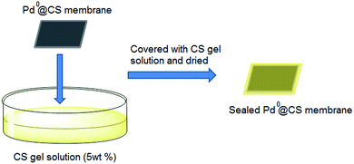
The preparation process of the common Pd@CS membrane catalyst was as follows. Under magnetic stirring, 1 g of CS was dissolved in 100 ml of 2 wt% acetic acid solution. Na2PdCl4 solution was prepared by dissolving of 0.15 g of PdCl2 in 50 ml of 2 wt% NaCl solution. 0, 2.5, 5, and 7.5 ml of Na2PdCl4 solution were dropped into the CS solution and magnetically stirred for another 0.25 h. The resultant gel solution was then casted on PTFE dishes, and was dried at 60 °C for about 4 h to form membranes. The membranes were immersed in 5 wt% NaOH bath for 0.5 h to remove the remaining acid. Then, the membranes were washed with deionized water to pH = 7. After drying at 60 °C, the Pd2+@CS membranes were prepared. The resultant Pd2+@CS membranes were further reduced to Pd0@CS membranes by immersing into 80 °C ethylene glycol bath for about 0.5 h. The color of the Pd0@CS membranes is much ducker than Pd2+@CS membranes, confirming the formation of Pd0 nanoparticles. The resulting Pd@CS membranes with different Pd addition amounts (2.5, 5, and 7.5 ml of Na2PdCl4 solution) were labeled as Pd@CS-1, Pd@CS-2, and Pd@CS-3, respectively.To deep assess the molecule transport behavior of the Pd0@CS membrane catalysts, we also prepared a number of CS layer sealed Pd0@CS membrane samples. The preparation process of the CS layer sealed Pd0@CS membrane samples were illustrated as Scheme 1. The resultant Pd0@CS membrane catalysts were coated completely with CS gel solution with high concentration (5 wt%). After drying at 60 °C, the common Pd0@CS membrane catalysts were then sealed completely with CS layers.
2.3 Catalytic application of Pd@CS membrane catalyst
In a 50 ml round bottom flask, a mixture of aryl iodide (1 mmol), acrylate (2 mmol), Pd@CS-3 membrane catalyst (0.005 mmol), CH3COOK (3 mmol), solvents (10 ml of dimethyl sulfoxide (DMSO) + 0.2 ml ethylene glycol) was stirred at 110 °C (heated in oil bath) for 5 h. The progress of the reactions was monitored by thin layer chromatography (TLC) and/or gas chromatography-mass spectrometry (GC/MS) analysis. The chemical structure and yield of the coupling reaction products were confirmed using 1H NMR and GC/MS analysis. The structure characterization results of the coupling products were consistent with our recent work.57 In recycling experiments, the filtered Pd0@CS membrane catalysts were rinsed with ethanol firstly, and then they were dried and reused in a second reaction run.2.4 Characterization of Pd@CS membrane catalyst
The mechanical properties of Pd@CS membrane catalysts were measured with a SANS universal materials testing instrument (Shenzhen SANS testing machine Co. Ltd., China) according to GB/T 1040.3-2006 (standard test method for tensile properties of plastic film of China), and the testing condition was, at 25 °C, with a crosshead speed of 50 mm min−1.The swelling ratio of the Pd@CS membrane catalysts in ethylene glycol and DMSO was determined as follows. The pre-weighed Pd@CS membrane samples were immersed in ethylene glycol or DMSO for 1 h at 110 °C with magnetic stirring. Then, the membrane samples were taken out of the solvents. The samples were weighed again after removing the excess solvents on the surface of the samples by tissue. The swelling ratio (S) of the membrane samples was calculated with eqn (3)
| S = (mt − m0)/m0 × 100% | (3) |
The thermal stability of the Pd@CS membrane catalysts was measured with a Mettler Toledo TGA/DSC 2 STARe system, and the testing condition was: air atmosphere, from 30 to 800 °C, at a scanning rate of 20 °C min−1.
The crystalline structure of Pd@CS membrane catalysts was measured with an Empyrean X-ray diffraction system and the testing condition was: diffraction angle 2θ from 3° to 70°, at a scanning rate of 2° min−1.
The binding energy of Pd was measured by a Thermo Scientific ESCALAB 250Xi X-ray photoelectron spectrometer. The morphology observation was performed with JEM-2100F high resolution transmission electron microscope (HR-TEM).
Pd contents within Pd@CS membrane catalyst were determined with a Leemann ICP-AES Prodigy XP inductively coupled plasma atomic emission spectrometer.
Positron annihilation lifetime measurements of the Pd@CS membrane samples were performed using an EG&G ORTEC fast-slow system, with a time resolution of about 210 ps (full width at half-maximum, FWHM). The positron source (22Na, 16 μCi) was NaCl (carrier free) which was deposited between two Kapton foils (7 μm in thickness). And then it was sandwiched in two stacks of identical pieces of Pd@CS membrane samples (1 cm in width, 1.5 mm in thickness). The total counts of the positron lifetime spectra of each sample were at least 3.5 × 10⁶ to achieve good statistics. Both LT-9 (Lifetime-9) program and MELT-4 (Maximum Entropy for Lifetime Analysis-4) programs were used to analyze the positron annihilation lifetime spectra with three components fitting.
3. Results and discussion
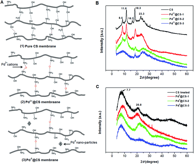
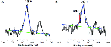
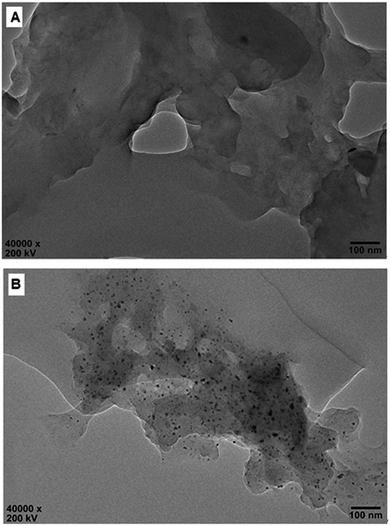
The molecule structure and crystalline structure of pure CS and prepared Pd@CS membranes are described in Fig. 1. For pure CS membrane, during the membrane preparation, strong inter-macromolecular hydrogen bonds have formed between the polar groups (–NH2 and/or –OH groups) of the macromolecules (Fig. 1A(1)). Pure CS membrane shows five diffraction peaks at 2θ of 8.5°, 11.6°, 16.2°, 18.3°, and 23.3°, respectively, indicating tight and regular packing of CS macromolecules. In the case of Pd2+@CS membranes, the added Pd2+ cations act as crosslinking points for CS macromolecules by their complex reactions mainly with the –NH2 groups (Fig. 1A(2)). As shown in Fig. 1B, the corresponding diffraction peaks of CS become much weaker and broader as the Pd2+ content increases, indicating the decrease in regularity packing of CS macromolecules. The reason should be due to the replacements of the hydrogen bonding by the Pd2+ induced crosslinking of the CS macromolecules. It is well known that Pd2+ cations are easily reduced by reductively solvents, like alcohols, DMSO, etc.32,33 The Pd2+@CS membranes were then reduced by ethylene glycol to prepare Pd0@CS membrane catalysts (Fig. 1A(3)). Same treatment was done to the pure CS membrane for comparing. As shown in Fig. 1C, the treated CS membrane shows only two broad diffraction peaks at 7.7° and 20.8°. It means that the tightness and regularity of CS macromolecules packing decreases obviously after the solvent permeation into the space of the CS macromolecules. Similar phenomenon is found for the Pd0@CS membrane catalyst prepared by the reduction of Pd2+@CS membrane with ethylene glycol. However, no obvious characteristic diffraction peaks for Pd0 nano-particles were detected, suggesting that both the content and size of the Pd0 nano-particles were below the detection limit of XRD.Nevertheless, the formation of Pd0 nano-particles can be well demonstrated by XPS characterization and HR-TEM observation. Fig. 2A shows the fresh Pd2+@CS-3 membrane has the characteristic Pd 3d5/2 electron binding energy peak at 337.8 eV, which is identical to that of the divalent palladium,58 confirming the Pd species in the fresh Pd2+@CS-3 membrane is in divalent state. In the case of Pd0@CS-3 membrane, as shown in Fig. 2B, besides the characteristic Pd 3d5/2 electron binding energy peak at 337.8 eV, a new peak at lower electron binding energy at 336.1 eV is detected. Although the peak at 336.1 is a bit weak in intensity, the appearance of this peak indicates that some of the Pd2+ species is reduced to Pd0 species.58 The Pd@CS-3 samples were embedded in epoxy resin, then microtomed, and finally imaged by HR-TEM. As shown in Fig. 3A, no individual separated Pd species are observed for the fresh Pd2+@CS membrane, indicating the added Pd2+ cations dispersed in molecular level in CS matrix. After reduction of Pd2+ to Pd0 by ethylene glycol, plenty of Pd0 nano-particles sized in about 5 nm are visualized in the CS matrix (Fig. 3B). It reveals that Pd0 species has less miscibility with CS matrix and form nano-sized aggregates dispersed in CS matrix.
The mechanical properties and swelling behavior of the Pd0@CS membrane catalyst are summarized in Table 1. Clearly, the Pd2+-induced crosslinking is advantageous for the improvement of the mechanical properties. For example, the tensile strength and modulus of the Pd0@CS-3 membrane catalyst are 24.9 MPa, and 619 MPa respectively, which is much higher than pure CS membrane. The equilibrium swelling ratio of the Pd0@CS membrane in solvents were determined as 56–62% in DMSO, and 89–91% in ethylene glycol. It is reasonable that high Pd contents and mechanical properties are in favor of high activity and stability in catalysis reactions. Therefore, in this study, we mainly focus on the Pd0@CS-3 membrane catalyst for its highest Pd content and mechanical properties.
| Samples | Tensile modulus (MPa) | Tensile strength (MPa) | Swelling ratio (%) | |
|---|---|---|---|---|
| DMSO | Ethylene glycol | |||
| CS | 237 | 11.8 | 57 | 86 |
| Pd0@CS-1 | 311 | 17.6 | 58 | 90 |
| Pd0@CS-2 | 472 | 22.3 | 56 | 89 |
| Pd0@CS-3 | 619 | 24.9 | 62 | 91 |
To obtain an in-depth understanding of the local environment of Pd species in CS matrix and the mechanism of the heterogeneous catalysis, PALS was applied as a powerful method to directly provide information on the micro-voids of the Pd@CS membrane with the resolution at molecular level. Firstly, the LT-program was used to fit the PALS spectra to evaluate the mean value of lifetimes and intensities. As shown in Table 2, the PALS spectra was fitted well in three-component lifetimes, p-Ps annihilation and free positron annihilation (shortest lifetime component, τ1, and its intensity, I1), free positron annihilation and positron trapping in the interfaces of CS and Pd species (intermediate lifetime component, τ2, and its intensity, I2), and o-Ps annihilation (longest lifetime component, τ3, I3). The free volume hole sizes in CS and Pd@CS membrane were then calculated by eqn (1) and eqn (2) from o-Ps lifetime, τ3. For pure CS membrane, the free volume hole diameter, D value was calculated as 0.5194 nm. With addition of Pd2+, it is found that the D value increases with the increase of the Pd2+ content. The D value of Pd2+@CS-1, Pd2+@CS-2, and Pd2+@CS-3 are 0.5424, 0.5466, and 0.5558 nm, respectively. It indicates that the open space between the CS macromolecules is enlarged with addition of Pd2+. For pure CS membrane, the main inter-macromolecular force is inter-macromolecular hydrogen bonding, which is formed by the directly interactions between the polar groups of neighboring CS macromolecules. In the case of Pd2+@CS membrane, the neighboring CS macromolecules are connected together by crosslinking points of Pd2+ cations. Therefore, it is reasonable that the open space between CS macromolecules will be enlarged for the introduction of crosslinking points of Pd2+ into CS inter-macromolecules. The effects of the reduction treatment of the membrane with ethylene glycol on the D value were also evaluated. It is found that the D value of pure CS membrane increases from 0.5194 to 0.6098 nm after treatment with ethylene glycol, suggesting that the open space between CS macromolecules is enlarged effectively after the entrance of the polar solvent of ethylene glycol. More interactions are formed between CS macromolecules and polar solvent of ethylene glycol. Therefore, the compactness and regularity of CS molecular chain segments stacking decrease obviously. This result is consistent with the results of XRD. Similarly, the free volume size of Pd0@CS membrane is bigger than Pd2+@CS membrane for the reduction treatment with ethylene glycol. The D value of Pd0@CS-1, Pd0@CS-2, and Pd0@CS-3 are 0.6046, 0.5998, and 0.5808 nm, respectively. For the Pd0@CS membranes, the D value decreases with the increase of the Pd content. It should be related to the crosslinking degree of Pd0@CS membranes. Pd0@CS membrane with higher Pd content has higher resistance to the solvents for its higher crosslinking degree. The MELT-4 program was further used to fit the PALS spectra of Pd@CS-3 to evaluate the distribution of the lifetimes. As shown in Fig. 4, for Pd2+@CS-3, the longest lifetime component should be attributed to the o-Ps annihilation in the Pd2+-crosslinked CS matrix. The distribution range of D value of Pd2+@CS-3 was estimated to be 0.44–0.51 nm calculated by eqn (1) and (2) from the o-Ps lifetime. The increase of the free volume hole size after reduction treatment of Pd2+ to Pd0 was also sensitively detected by PALS fitted with MELT-4 program. For Pd0@CS-3, the distribution of D value was estimated to be 0.51–0.58 nm.
| Samples | τ1 (ns) | I1 (%) | τ2 (ns) | I2 (%) | τ3 (ns) | I3 (%) | D (nm) |
|---|---|---|---|---|---|---|---|
| CS | 0.1899 ± 0.0036 | 50.2 ± 1.0 | 0.4465 ± 0.0083 | 38.4 ± 1.0 | 1.733 ± 0.009 | 11.4 ± 0.3 | 0.5181 ± 0.0018 |
| Pd2+@CS-1 | 0.1930 ± 0.0034 | 51.1 ± 1.1 | 0.4345 ± 0.0082 | 39.5 ± 1.1 | 1.855 ± 0.012 | 9.4 ± 0.2 | 0.5424 ± 0.0023 |
| Pd2+@CS-2 | 0.1963 ± 0.0034 | 54.0 ± 1.1 | 0.4414 ± 0.0077 | 37.5 ± 1.1 | 1.877 ± 0.015 | 8.5 ± 0.2 | 0.5466 ± 0.0029 |
| Pd2+@CS-3 | 0.1977 ± 0.0032 | 56.0 ± 1.1 | 0.4428 ± 0.0082 | 36.5 ± 1.1 | 1.925 ± 0.015 | 7.5 ± 0.2 | 0.5558 ± 0.0028 |
| CS treated | 0.1841 ± 0.0034 | 46.9 ± 1.1 | 0.4308 ± 0.0073 | 39.7 ± 1.0 | 2.228 ± 0.010 | 13.4 ± 0.3 | 0.6098 ± 0.0016 |
| Pd0@CS-1 | 0.1782 ± 0.0036 | 43.9 ± 1.1 | 0.4019 ± 0.0063 | 44.5 ± 1.1 | 2.198 ± 0.012 | 11.6 ± 0.3 | 0.6046 ± 0.0021 |
| Pd0@CS-2 | 0.1780 ± 0.0039 | 44.8 ± 1.1 | 0.4000 ± 0.0058 | 44.9 ± 1.1 | 2.170 ± 0.013 | 10.3 ± 0.2 | 0.5998 ± 0.0023 |
| Pd0@CS-3 | 0.2007 ± 0.0037 | 54.9 ± 1.2 | 0.4042 ± 0.0078 | 38.5 ± 1.2 | 2.061 ± 0.013 | 6.6 ± 0.2 | 0.5808 ± 0.0023 |
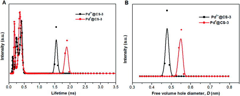 | ||
| Fig. 4 The distribution of positron annihilation lifetime (A) and free volume hole size of the Pd@CS-3 membrane (B) analyzed by MELT program. | ||
Pd0-catalyzed Heck coupling reaction is one of the most powerful and versatile methods to construct new C–C bonds linked to unsaturated double bonds. In this study, Heck coupling reactions between aryl iodides and acrylates with different molecule size has been catalyzed by Pd0@CS-3 and CS layer sealed Pd0@CS-3. The main purpose is to assess the probabilities of the free volume holes as the molecules transport channels for the reactions. It should be noted here that, due to the swelling effects of solvent (DMSO swelling) and high temperature condition (110 °C), the open spaces between the CS macromolecules of the Pd0@CS-3 membrane catalyst in real reaction application should be enlarged much as compared to its dry state.59–61 Therefore, an approximate evaluation of the free volume hole diameter of the swollen Pd0@CS membrane in the reaction system was done firstly. Considering the swelling effect of solvent to the membrane catalyst, the free volume hole diameter of swollen Pd0@CS-3 membrane in the reaction system might be adjusted with the following eqn (4).41
| Ds = D × (100% + swelling ratio) | (4) |
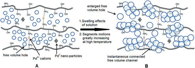
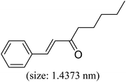
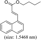
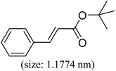
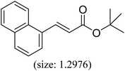
As we know, for Pd0@CS membrane catalyst, the Pd0 nanoparticles were well entrapped in the CS matrix. It is believed that the coupling reactions can occur only when the reactants molecules are able to diffuse into the Pd0@CS-3 membrane and get access to the nano-Pd0 catalyst. Therefore, the size of the open spaces of the membrane catalyst should be at least bigger than that of the involving molecules of the reactions. As shown in Table 3, for comparing, the mean Ds value of Pd0@CS-3 membrane (0.9409 nm) is bigger than the molecule size of the reactants of iodo benzene, iodine naphthalene, and tert-butyl acrylate; a bit smaller than that of substrates of iodine fluorine, and n-butyl acrylate; and much smaller than that of all the products molecules. It seems that the catalytic activity of the Pd0@CS-3 membrane catalyst should not be so good for the coupling reaction of these reactants. However, the reaction results show that the Pd0@CS-3 membrane catalyst has high catalytic activity for all the substrates with different molecule size. It revealed that many open spaces with big enough size should be induced within the CS matrix during the reaction to allow the reactants molecules and the products molecules diffusing freely in the membrane. To test this hypothesis, the Pd0@CS-3 membrane catalyst was further sealed with pure CS coating layer and applied in the same Heck coupling reactions. As shown in Table 3, although the coupling yields of all entries (especially in the entries of 2, 3, 5, 6 of big-sized reactants) are reasonably reduced obviously, the Heck coupling reactions of each entry can still be catalyzed by such CS layer sealed Pd0@CS-3 membrane catalyst, indicating that the involving molecules of reactions are able to diffuse through the open spaces of the CS layer. These results powerfully demonstrate that the open spaces of Pd0@CS-3 membrane catalyst should be enlarged enough for molecules transport during the reactions. The molecules transport channels of Pd0@CS membrane catalyst in the reaction should be through a number of instantaneously connected free volume holes rather than a single free volume hole. The catalysis mechanism of the Pd0@CS-3 membrane catalyst from the aspect of free volume could be illustrated in Scheme 2. On the one hand, when applied in Heck reactions, the swelling effects of the solvent to the Pd0@CS-3 membrane catalyst will lead to an increase of the open spaces between CS macromolecules. As a result, the free volume hole size of the swollen Pd0@CS-3 membrane is enlarged to some extent (as shown in Scheme 2B). On the other hand, the movement ability of CS segments of the Pd0@CS-3 membrane catalyst will be improved remarkably in the reaction system at high temperature (110 °C). Meanwhile, a number of neighboring free volume holes might undergo instantaneously connected during the segments motions to form much enlarged free volume hole channels (as shown in Scheme 2B), which provides enough space for substrates and the coupling products molecules diffusing freely in the membrane catalyst.
| Entry | Aryl iodide | Acrylates | Products | Yieldb (%) | |
|---|---|---|---|---|---|
| A | B | ||||
| a Reaction conditions: 1 mmol aryl iodide, 2 mmol acrylate, 0.005 mmol Pd@CS membrane catalyst, 3 mmol CH3COOK, in 10 ml DMSO + 0.2 ml ethylene glycol solution, 110 °C, 5 h.b GC/MS yield.c Molecule size estimated with its bond parameters. | |||||
| 1 |  |
 |
 |
99 | 74 |
| 2 |  |
 |
 |
87 | 48 |
| 3 |  |
 |
 |
86 | 35 |
| 4 |  |
 |
 |
96 | 61 |
| 5 |  |
 |
 |
85 | 41 |
| 6 |  |
 |
 |
82 | 32 |
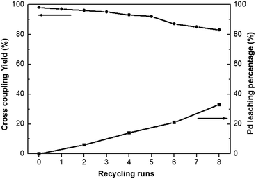
Heterogeneous catalysts often contain the advantage of easy separation and recycling from the reaction mixture. Heck coupling reaction of iodobenzene with n-butyl acrylate has been employed as a model reaction to assess the stability and reusability of the Pd0@CS-3 membrane catalyst. As shown in Fig. 5, Pd0@CS-3 membrane catalyst can be recycled for more than 8 times with no significant decrease in coupling yield. The Pd leaching percentage of the recycled Pd0@CS-3 membrane catalyst had been monitored with ICP. It is found that about 60% of Pd is still retained in the recycled Pd0@CS-3 membrane catalyst after reuse of 8 times, suggesting fairly good stability.
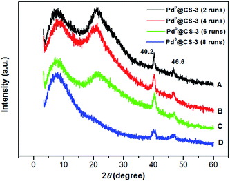
Examination of Fig. 6 shows the changes in the crystalline structure of the reused Pd0@CS-3 membrane catalyst with the increasing of the recycling runs. Characteristic diffraction peaks at 2θ degree of 40.2° and 46.6° of the crystal of Pd0 species have been detected for the reused Pd0@CS-3 membrane catalyst, indicating that more Pd2+ species have been reduced to Pd0 nano-particles to form perfect crystals during the catalytic reactions. The characteristic diffraction peaks of the crystal Pd0 species become obviously weaker after the Pd0@CS-3 membrane catalyst reused for 8 runs. This is mainly due to the Pd leaching during the recycling of the Pd0@CS-3 membrane catalyst.
Fig. 7 shows the HR-TEM images of the reused Pd0@CS membrane catalyst. In the case of Pd0@CS membrane catalyst reused for 4 runs, besides plenty of Pd0 nano-particles in the similar size (about 5 nm) with those of the fresh Pd0@CS membrane catalyst (Fig. 3B), there are many Pd0 nanoparticle aggregates with bigger size of about 10–30 nm dispersed in the CS matrix. In the case of Pd0@CS membrane catalyst reused for 8 runs, the numbers of Pd0 nanoparticles decreases obviously, and most of the dispersed Pd0 nanoparticles are in bigger size of about 10–30 nm, suggesting the leaching of the small sized Pd0 nano-particles. These results are well in accordance with the results of XRD characterization.
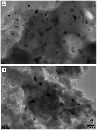 | ||
| Fig. 7 HR-TEM observation of the reused Pd0@CS-3 membrane catalyst with different recycling runs: (A) 4 runs; (B) 8 runs. | ||
The TGA–DTG curves of the recycled Pd0@CS-3 are shown in Fig. 8. For fresh Pd0@CS membrane catalyst, it has three weight loss stages at 50–120 °C (absorbed water evaporation), 215–376 °C (destruction of the intermolecular interactions such as hydrogen bonding and crosslinking, decomposition of chitosan macromolecules, and carbonization), and 553–762 °C (deep decomposition, carbonization, and thermal oxidation). The weight loss peak temperatures of each stage from the DTG curve of fresh Pd0@CS membrane catalyst was estimated as to be 89, 291, and 708 °C, respectively. Except a bit lower shifts in the corresponding weight loss peak temperatures, the Pd0@CS membrane catalysts reused up to 6 runs have similar weight loss stages with fresh Pd0@CS membrane catalyst. In the case of Pd0@CS membrane catalyst reused for 8 runs, the third weight loss stage and its corresponding peak temperature shifts to 484–645 °C, and 515 °C, respectively, suggesting obviously drop in the thermal stability. The decrease in thermal stability is due to the physical aging caused by prolonged use under harsh reaction conditions, such as high reaction temperature (110 °C), continuous long-time processing (reused for 8 runs), and swelling of the solvents (polar solvents corrosions), and so on.
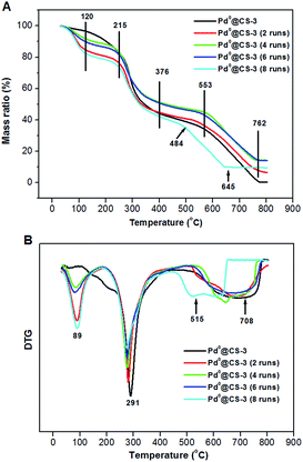 | ||
| Fig. 8 TGA curves (A) and DTG curves (B) of the reused Pd0@CS-3 membrane catalysts with different recycling runs. | ||
The mean value of lifetimes and intensities of the reused Pd0@CS-3 membrane catalyst are summarized in Table 4. It is found that the free volume hole size (D) of the reused Pd0@CS membrane catalyst increased as the increase of the reusing runs, suggesting a decrease in the compactness of the segments packing of CS macromolecules. On the one hand, during recycling, the Pd leaching and the formation of more Pd0-nanoparticles with big size will lead to a decrease of crosslinking effects of Pd2+. On the other hand, the CS matrix will undergo degradation for the long-time continuous processing of the recycled Pd0@CS-3 membrane catalyst at high temperature. The changes of the distribution of the lifetimes and free volume hole size of the reused Pd0@CS-3 membrane catalyst is shown in Fig. 9. It is found that the distribution peak of free volume size of the reused Pd0@CS-3 membrane catalyst shifts to bigger size range as the reusing runs increased. Meanwhile, the distribution peak of free volume size becomes much broader after the Pd0@CS-3 membrane catalyst was reused for more than 4 runs. The enlarged free volume holes must also act as the Pd leaching channels of the reused Pd0@CS-3 membrane catalyst. We then take similar approximate evaluation (by eqn (4)) of the mean free volume size (Ds, as shown in Table 4) of the swollen reused Pd0@CS-3 membrane catalyst in the reaction solution. Clearly, most of the Pd0 nanoparticles have bigger size (as shown in HR-TEM images) than single free volume hole of the Pd0@CS-3 membrane catalyst. It indicates the Pd leaching is mainly achieved through a number of instantaneously connected free volume holes rather than a single free volume hole.
| Sample | τ1 (ns) | I1 (%) | τ2 (ns) | I2 (%) | τ3 (ns) | I3 (%) | D (nm) | Ds (nm) |
|---|---|---|---|---|---|---|---|---|
| Pd0@CS-3 (2 runs) | 0.2430 ± 0.0044 | 53.8 ± 1.3 | 0.4780 ± 0.010 | 38.0 ± 1.2 | 2.288 ± 0.013 | 8.2 ± 0.3 | 0.6198 ± 0.0020 | 1.0041 ± 0.0032 |
| Pd0@CS-3 (4 runs) | 0.2217 ± 0.0028 | 60.4 ± 1.0 | 0.4844 ± 0.009 | 32.4 ± 1.0 | 2.375 ± 0.014 | 7.2 ± 0.2 | 0.6340 ± 0.0021 | 1.0271 ± 0.0034 |
| Pd0@CS-3 (6 runs) | 0.2415 ± 0.0039 | 63.9 ± 1.0 | 0.5272 ± 0.007 | 29.3 ± 0.8 | 2.425 ± 0.011 | 6.8 ± 0.2 | 0.6418 ± 0.0018 | 1.0397 ± 0.0029 |
| Pd0@CS-3 (8 runs) | 0.2409 ± 0.0046 | 65.4 ± 1.1 | 0.5171 ± 0.007 | 28.7 ± 0.9 | 2.450 ± 0.013 | 5.9 ± 0.3 | 0.6458 ± 0.0021 | 1.0461 ± 0.0034 |
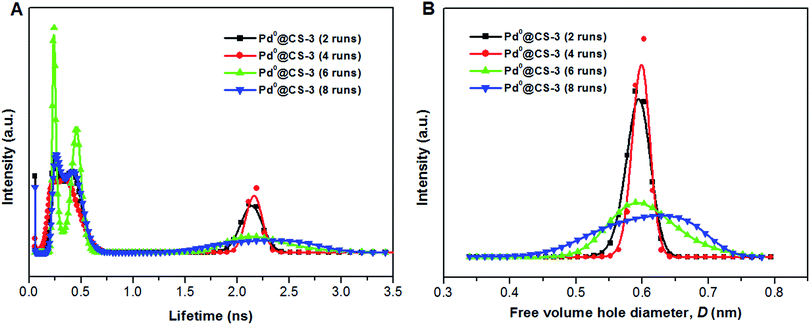 | ||
| Fig. 9 The distribution of positron annihilation lifetime (A) and free volume hole size of the reused Pd0@CS-3 membrane catalyst (B) analyzed by MELT program. | ||
4. Conclusions
In this study, we have combined the positron annihilation lifetime spectrum and other structural characterization methods to elucidate the correlations between the microstructure and the catalytic performances of Pd@CS membrane heterogeneous catalysts. It was found that the in situ reduction of Pd2+ into Pd0 nanoparticles in the interstices of CS macromolecules was effectively entrapped in the matrices of Pd0@CS membrane, which still allowed the diffusion of reactant and product molecules through the matrices. We demonstrated that molecules transport channels of Pd0@CS membrane catalyst in the reaction at high temperature was through a number of instantaneously connected free volume holes rather than a single free volume hole. The findings in this study may be useful to further understand the catalytic mechanism in molecular level of transition metals supported on biopolymers heterogeneous catalysts, in pursuit of rational development of efficient catalysis reaction system.Conflicts of interest
There are no conflicts to declare.Acknowledgements
The authors acknowledge the financial support from the National Natural Science Foundation of China (grant number: No. 11475114 and 11575117), Zhejiang Province Fundamental Public Welfare Research Project (grant number: No. LGG18E030004), and High-level Talents Further Study Abroad Support Plan of Shaoxing City. We would like to thank Prof. Y. Lin (Institute of Materials Science and Department of Chemistry, University of Connecticut) for his helpful discussions.References
- J. Tsuji, Palladium Reagents and Catalyst, Wiley, New York, 2004 Search PubMed.
- D. J. Cole-Hamilton and R. P. Tooze, Homogeneous catalysis-advantages and problems, in Catalyst Separation, Recovery and Recycling; Chemistry and Process Design, Springer, Dordrecht, Germany, 2006, ch. 1 Search PubMed.
- J. M. Thomas and W. J. Thomas, Principles and Practice of Heterogeneous Catalysis, Wiley-VCH, Weinheim, Germany, 1996 Search PubMed.
- L. Yin and J. Liebscher, Chem. Rev., 2007, 107, 133–173 CrossRef CAS PubMed.
- E. Nehlig, B. Waggeh, N. Millot, Y. Lalatonne, L. Motte and E. Guenin, Dalton Trans., 2015, 44, 501–505 RSC.
- N. Mizuno and M. Misono, Chem. Rev., 1998, 98, 199–217 CrossRef CAS PubMed.
- L. Djakovitch and K. Koehler, J. Am. Chem. Soc., 2001, 123, 5990–5999 CrossRef CAS PubMed.
- S. Scire, R. Fiorenza, A. Gulino, A. Cristaldi and P. M. Riccobene, Appl. Catal., A, 2016, 520, 82–91 CrossRef CAS.
- J. S. Yoon, T. H. Lee, J.-W. Choi, D. J. Suh, K. Lee, J.-M. Ha and J. Choi, Catal. Today, 2017, 293–294, 142–150 CrossRef CAS.
- U. Akhmetzyanova, M. Opanasenko, J. Horacek, E. Montanari, J. Cejk and O. Kikhtyanin, Microporous Mesoporous Mater., 2017, 252, 116–124 CrossRef CAS.
- M. Mora, C. Jimenez-Sanchidrian and J. R. Ruiz, Curr. Org. Chem., 2012, 16(9), 1128–1150 CrossRef CAS.
- T. Borkowski, J. Dobosz, W. Tylus and A. M. Trzeciak, J. Catal., 2014, 319, 87–94 CrossRef CAS.
- C. Y. Dai, Y. G. Li, C. L. Ning, W. X. Zhang, X. G. Wang and C. L. Zhang, Appl. Catal., A, 2017, 54, 97–103 CrossRef.
- T. Mochizuki, Y. Abe, S. Y. Chen, M. Toba and Y. Yoshimura, ChemCatChem, 2017, 9(14), 2633–2637 CrossRef CAS.
- A. Srinivasan and C. Depcik, Catal. Rev., 2010, 52(4), 462–493 CAS.
- S. Sahoo, A. Bordoloi and S. B. Halligudi, Catal. Surv. Asia, 2011, 15(3), 200–214 CrossRef CAS.
- M. Gholinejad and J. Ahmadi, ChemPlusChem, 2015, 80, 973–979 CrossRef CAS.
- G. J. Barbante, T. D. Ashton, E. H. Doeven, F. M. Pfeffer, D. Wilson, L. C. Henderson and P. S. Francis, ChemCatChem, 2015, 7(11), 1655–1658 CrossRef CAS.
- P. P. Sarmah and D. K. Dutta, Appl. Catal., A, 2014, 470, 355–360 CrossRef CAS.
- B. J. Borah, S. J. Borah, K. Saikia and D. K. Dutta, Appl. Catal., A, 2014, 469, 350–356 CrossRef CAS.
- D. Dutta and D. K. Dutta, Appl. Catal., A, 2014, 487, 158–164 CrossRef CAS.
- T. Baran, J. Colloid Interface Sci., 2017, 496, 446–455 CrossRef CAS PubMed.
- A. Khalafi-Nezhad and F. Panahi, Green Chem., 2011, 13(9), 2408–2415 RSC.
- S. Sabaqian, F. Nemati, H. T. Nahzomi and M. M. Heravi, Carbohydr. Polym., 2017, 177, 165–177 CrossRef CAS PubMed.
- Y. Z. Li, L. Xu, B. Xu, Z. P. Mao, H. Xu, Y. Zhong, L. P. Zhang, B. J. Wang and X. F. Sui, ACS Appl. Mater. Interfaces, 2017, 9(20), 17156–17163 Search PubMed.
- D. Kale, G. Rashinkar, A. Kumbhar and R. Salunkhe, React. Funct. Polym., 2017, 116, 9–16 CrossRef CAS.
- M. Thomas and M. U. D. Sheikh, J. Colloid Interface Sci., 2017, 505, 115–129 CrossRef CAS PubMed.
- M. Chtchigrovsky, Y. Lin, K. Ouchaou, M. Chaumontet, M. Robitzer, F. Quignard, F. Taran and D. Ahirwar, Chem. Mater., 2012, 24(8), 1505–1510 CrossRef CAS.
- S. Wang, H. Y. Zhou, S. S. Song and J. X. Wang, Chin. J. Org. Chem., 2015, 35, 85–91 CrossRef CAS.
- B. C. E. Makhubela, A. Jardine and G. S. Smith, Green Chem., 2012, 14(2), 338–347 RSC.
- T. Baran, E. Aciksoz and A. Mentes, Carbohydr. Polym., 2016, 142, 189–198 CrossRef CAS PubMed.
- M. F. Zeng, C. Z. Qi and X.-M. Zhang, Int. J. Biol. Macromol., 2013, 55, 240–245 CrossRef CAS PubMed.
- M. F. Zeng, X. Yuan, S. F. Zuo and C. Z. Qi, RSC Adv., 2015, 5, 37995–38000 RSC.
- E. Guibal, Prog. Polym. Sci., 2005, 30, 71–109 CrossRef CAS.
- A. El Kadib, ChemSusChem, 2015, 8, 217–244 CrossRef CAS PubMed.
- C. R. Kothapalli, M. T. Shaw and M. Wei, Acta Biomater., 2005, 1, 653–662 CrossRef PubMed.
- X. F. Zeng and E. Ruckenstein, J. Membr. Sci., 1998, 148, 195–205 CrossRef CAS.
- H. Ennajih, R. Bouhfid, E. M. Essassi, M. Bousmina and A. El Kadib, Microporous Mesoporous Mater., 2012, 152, 208–213 CrossRef CAS.
- M. F. Zeng, X. Yuan, Z. Yang and C. Z. Qi, Int. J. Biol. Macromol., 2014, 68, 189–197 CrossRef CAS PubMed.
- M. Bradshaw, J. L. Zou, L. Byrne, K. S. Iyer, S. G. Stewart and C. L. Raston, Chem. Commun., 2011, 47, 12292–12294 RSC.
- M. F. Zeng, C. Z. Qi, J. Yang, B. Y. Wang and X.-M. Zhang, Ind. Eng. Chem. Res., 2014, 53, 10041–10050 CrossRef CAS.
- K. Martina, S. E. S. Leonhardt, B. Ondruschka, M. Curini, A. Binello and G. Cravotto, J. Mol. Catal. A: Chem., 2011, 334, 60–64 CrossRef CAS.
- S. E. S. Leonhardt, A. Stolle, B. Ondruschka, G. Cravotto, C. D. Leo, K. D. Jandt and T. F. Keller, Appl. Catal., A, 2010, 379, 30–37 CrossRef CAS.
- K. Zhan, H. H. You, W. Y. Liu, J. Lu, P. Lu and J. Dong, React. Funct. Polym., 2011, 71, 756–765 CrossRef CAS.
- C. S. Yin, L. T. Wang, J. J. Li, Y. W. Zhou, H. N. Zhang, P. F. Fang and C. Q. He, Phys. Chem. Chem. Phys., 2017, 19, 15953–15961 RSC.
- T. Fujioka, O. Nagayasu, R. Suzuki, W. E. Price and L. D. Nghiem, J. Membr. Sci., 2015, 486, 106–118 CrossRef CAS.
- S. K. Rath, S. S. Edatholath, T. U. Patro, K. Sudarshan, P. U. Sastry, P. K. Pujari and G. Harikrishnan, Phys. Chem. Chem. Phys., 2016, 18, 2682–2689 RSC.
- Y. Liu, S. N. Yu, H. Wu, Y. F. Li, S. F. Wang, Z. Z. Tian and Z. Y. Jiang, J. Membr. Sci., 2014, 469, 198–208 CrossRef CAS.
- Y. F. Li, X. Q. Li, H. Wu, Q. P. Xin, S. F. Wang, Y. Liu, Z. Z. Tian, T. T. Zhou, Z. Y. Jiang, H. W. Tian, X. Z. Cao and B. Y. Wang, J. Membr. Sci., 2015, 493, 460–469 CrossRef CAS.
- J. R. Weidman, S. J. Luo, C. M. Doherty, A. J. Hill, P. Y. Gao and R. L. Guo, J. Membr. Sci., 2017, 522, 12–22 CrossRef CAS.
- R. A. Pethrick, Prog. Polym. Sci., 1997, 22, 1–43 CrossRef CAS.
- Y. C. Jean, J. D. Van Horn, W. S. Hung and K. R. Lee, Macromolecules, 2013, 46(18), 7133–7145 CrossRef CAS.
- Q. F. An, W. S. Hung, S. C. Lo, Y. H. Li, M. De Guzman, C. C. Hu, K. R. Lee, Y. C. Jean and J. Y. Lai, Macromolecules, 2012, 45(8), 3428–3435 CrossRef CAS.
- H. F. M. Mohamed, K. Ito, Y. Kobayashi, N. Takimoto, Y. Takeoka and A. Ohira, Polymer, 2008, 49, 3091–3097 CrossRef CAS.
- S. J. Tao, J. Chem. Phys., 1972, 56, 5499–5510 CrossRef CAS.
- M. Eldrup, D. Lightbody and J. N. Sherwood, Chem. Phys., 1981, 63, 51–58 CrossRef CAS.
- M. F. Zeng, Y. D. Wang, Q. Liu, X. Yuan, S. F. Zuo, R. K. Feng, J. Yang, B. Y. Wang, C. Z. Qi and Y. Lin, ACS Appl. Mater. Interfaces, 2016, 8, 33157–33164 CAS.
- C. D. Wagner, W. M. Riggs, L. E. Davis and G. E. Mullenberg, Handbook of X-Ray Photoelectron Spectroscopy, Perkin-Elmer, Minnesota, 1979 Search PubMed.
- C. M. Paranhos, B. G. Soares, J. C. Machado, D. Windmöller and L. A. Pessan, Eur. Polym. J., 2007, 43, 4882–4890 CrossRef CAS.
- P. N. Patil, S. Kathi, D. Dutta and P. K. Pujari, Polym. Bull., 2010, 65, 577–587 CrossRef CAS.
- R. M. Hodge, G. P. Simon, M. R. Whittaker and D. J. T. Hill, J. Polym. Sci., Part B: Polym. Phys., 1998, 36, 463–471 CrossRef CAS.
| This journal is © The Royal Society of Chemistry 2018 |

