 Open Access Article
Dense and thin 13X membranes on porous α-Al2O3 tubes: preparation, structure and deep purification of oxygenated compounds from gaseous olefin flow
Yongxian Zhouab,
Wei Chen b,
Pengfei Wang*b and
Yimin Zhang*a
aKey Laboratory for Green Chemical Technology of State Education Ministry, School of Chemical Engineering and Technology, Tianjin University, Tianjin 300350, P. R. China. E-mail: zhangym@tju.edu.cn; Fax: +86-22-27401999; Tel: +86-22-27401999
bState Key Laboratory of Polyolefin Catalytic Technology and High Performance Materials, Shanghai Research Institute of Chemical Industry Co., Ltd, Shanghai 200062, P. R. China. E-mail: wpf@sricims.com; Fax: +86-21-69577870; Tel: +86-21-69577696-8005
First published on 12th April 2018
Abstract
The low contact efficiency, large mass transfer resistance and high operational cost of traditional 13X molecular sieve particle adsorbents (MSPs) have greatly limited their application in deep purification of trace oxygenated compounds from gaseous olefins. Herein, we successfully fabricated dense and thin 13X molecular sieve membranes on a porous α-Al2O3 tube (MSCMs) by a combination of 3-aminopropyl triethoxy silane (APTES) surface modification and vacuum pre-coating sol technology for purifying the above impurities. By a solid–solution transformation process, 13X molecular sieve membranes on MSCMs that were continuous and integral without any cracks, pinholes or other defects, and mainly composed of 1–1.5 μm regular 13X crystals with a thickness of 5–6 μm have been achieved. The purification performance of the MSPs, non-APTES functionalized MSCMs (nMSCMs) and MSCMs was evaluated by dynamic adsorption of N2 or C2H4 feed flow containing dimethyl ether, methanol and propanal impurities at room temperature. The results demonstrated that both the nMSCMs and MSCMs could deeply purify the trace amounts of the three oxygenated compounds to below 1 × 10⁻⁶ (mol mol−1) from gaseous olefins at an initial concentration of 20 × 10−6 (mol mol−1), exhibiting much more excellent purification performance than that of MSPs. In particular, the breakthrough times of MSCMs for dimethyl ether, methanol and propanal were 7 h, 32 h and 51 h in a N2 system, and 12.1 h, 53 h and 90 h in a C2H4 system. The cumulative adsorption amounts of MSCMs for dimethyl ether, methanol and propanal were 12.108 mg g−1, 35.812 mg g−1 and 103.129 mg g−1 in a N2 system, and 25.88 mg g−1, 94.19 mg g−1 and 256.26 mg g−1 in a C2H4 system, respectively. The regeneration experiment also indicated that the MSCMs had a more stable structure and a longer lifetime. The excellent purification performance of MSCMs could be attributed to the continuous 13X molecular sieve layers without non-adsorption interfacial voids. Hence, the MSCMs have great potential for future industrial application of trace oxygenated compound removal from gaseous olefins.
1. Introduction
The polyolefin industry is the pillar of the petrochemical industry, which occupies an important strategic position in our country. As the key precondition of olefin polymerization, polymer-grade olefin purification technology not only has a great influence on the polyolefin quality and yield, but also exerts a dominant effect on the future development of the downstream plastics industry. In today’s plastic world, C2 to C4 light hydrocarbons such as ethylene, propylene and butylene rank among the most important petrochemical commodities. Notably, with the upgrading of olefin polymerization catalysts, the requirement for purity of the raw materials of these catalysts has become higher and higher. Recently, a series of common technologies have been used to produce olefins including steam cracking,1 catalytic cracking,2 catalytic dehydrogenation,3 methanol to propylene (MTP),4 methanol to olefins (MTO)5 and so on. Unfortunately, all of the olefins prepared by the traditional cracking methods and the new MTP and MTO processes contain various impurities, such as H2O, O2, CO, CO2, methanol, dimethyl ether, propanal, acetone, and carbonyl sulfur.6–10 In particular, the presence of trace methanol, dimethyl ether and propanal can seriously affect the activity of the polyolefin catalysts. Even worse, these impurities may cause the whole plant to be discontinued because of catalyst poisoning. If this situation happens, it will cause a significant economic loss.It is well known that a granular, alumina and molecular sieve composite adsorbent, as a mature industrial method, has been widely adopted to deeply purify these oxygenated impurities from olefins to below 1 × 10⁻⁶ (mol mol−1).11 However, the disadvantages of large mass transfer resistance, greater abrasion, small contact areas, large occupied areas and especially the huge regeneration energy consumption are detrimental to energy conservation and emission reduction. These disadvantages will significantly increase the operational cost. Therefore, there is an urgent need to develop a novel material instead of the granular purification adsorbent to deeply purify the above impurities.
Due to the high removal accuracy, low pollution, low energy consumption and easy to achieve continuous separation, membrane (polymeric and molecular sieve membranes) adsorption and separation technology has been widely used in many industries such as chemical, food, medicine, environmental protection, metallurgy and other industrial fields.12,13 Since Suzuki patented the first preparation in 1987,14 molecular sieve membranes are gaining increasing interest because of their higher separation selectivity and superior thermal, mechanical, anti-corrosive and chemical properties compared to polymeric membranes.15,16 Moreover, molecular sieve membranes also have lower mass transfer resistance and larger infiltration flux. The controlled host adsorbate performance of the uniform and tunable molecular-sized pore structure makes it attractive as a new shape-selective material for gas separation and impurity removal.17 So far, many kinds of molecular sieve membranes have been studied such as A-type,18 T-type,19 SAPO-34,20 DDR,21,22 ZSM-5,23 Y-type24 and X-type25 molecular sieves.
Because of the special spatial framework, and relatively large pore diameter of 10 Å, Na–X molecular sieve membranes have been widely used in separation, such as the dehydration of organic solvents and separation of 1,3-propanediol from aqueous solutions by steam permeation.26,27 Inspired by these studies, it can be hypothesized that Na–X molecular sieve membranes could be ideal for deeply removing oxygenated compounds from olefins. Fortunately, in the previous studies, a number of methods have been applied to prepare molecular sieve membranes.28–31 Due to the shorter crystal nucleation period and higher continuous membrane synthesis efficiency, the secondary growth method is supposed to be the most extensive and effective strategy in preparing molecular sieve membranes.32,33 Unfortunately, so far, the growth of Na–X molecular sieve layers on a porous support without cracks, pinholes or other defects is still a great challenge, which directly undermines the adsorption or separation properties. Recently, researchers have found that the inhomogeneous nucleation and electrostatic repulsion between precursor species and supports are the main reasons for the failure of achieving defect-free Na–X molecular sieve layers.34 When the α-Al2O3 tubes are in contact with alkaline aqueous solutions, the surface hydroxyl groups will lose protons so as to change the surface charge from positive to negative.35 This charge transformation enhances the electrostatic rejection between the molecular sieve precursor species and the α-Al2O3 tubes. Therefore, various strategies have been developed to promote homogeneous nucleation and minimize electrostatic rejection, especially sol coating technology and surface chemical modification. Specifically, vacuum pre-coating sol technology is the most likely industrialized method to obtain continuous crystal layers and is widely used. However, the repeatability and stability of Na–X molecular sieve membranes with dense and thin layers are still not very desirable. Silane coupling agents with rich hydrolysable groups were commonly proposed to improve the surface chemical properties of ceramic supports. As a kind of silane coupling agent, (3-aminopropyl)triethoxy silane (APTES) has been used as a molecular linker in protein immobilization and nanoparticle stabilization due to its rich functional groups, such as methoxy, ethoxy and acetoxy.36–38 For example, Huang has successfully used the APTES to act as a covalent linker to prepare dense and pure zeolite FAU membranes.39 However, there are still few researchers who have combined the vacuum pre-coating sol and APTES modification technology to synthesize 13X molecular sieve membranes.
Herein, in the present work, we have successfully prepared continuous MSCMs with dense and thin molecular sieve membranes by (3-aminopropyl)triethoxy silane (APTES) pretreatment and ensuing vacuum pre-coating sol technology on the α-Al2O3 tubes for deep removal of impurities from gaseous olefins. To achieve this, the MSCMs were prepared by the following steps: (i) surface modification of the α-Al2O3 tubes with APTES after calcination and polishing; (ii) sol coating on the surfaces of the pretreated α-Al2O3 tubes via vacuum pre-coating technology; and (iii) hydrothermal synthesis of MSCMs under rotation using sodium aluminate as an aluminium source, sodium silicate as a silicon source and sodium hydroxide as a sodium source. The main objectives of this study are to fabricate MSCMs with dense and thin molecular sieve layers as well as to study the morphology, structure and formation mechanism. Moreover, we also aim to provide MSCMs with excellent properties compared to those of the traditional MSPs to deeply purify the impurities from gaseous olefins for future industrial applications. For comparison, traditional MSPs and the MSCMs without APTES pretreatment were also investigated. Scheme 1 is the oxygenated compounds purification mechanism schematic of the 13X molecular sieve membranes: under the large pressure difference, the gaseous feed containing impurities was passed through the 13X molecular sieve membranes. Due to the selective adsorption of the pore channels, the relatively smaller oxygenated compounds entered into the molecular sieve pores, and then the polymer-grade olefins were obtained.
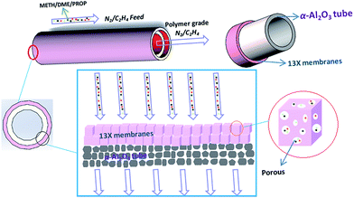 | ||
| Scheme 1 A schematic of the mechanism by which the 13X molecular sieve membranes purify oxygenated compounds. | ||
2. Experimental
2.1 Materials and reagents
Sodium hydroxide pellets (96%, AR), sodium aluminate (41%, CP) and sodium silicate (19.1–22.8%, AR) were all purchased from Shanghai Zhongyuan Chemical Co., Ltd. (3-Aminopropyl)triethoxy silane (APTES, 98%, AR) was purchased from Aladdin, and toluene (96%, AR) was purchased from Sinopharm Chemical Reagent Co., Ltd. The tubular α-Al2O3 support (outer diameter 12 mm, inner diameter 8 mm) with an average pore size of 2–5 μm and a porosity of 38% was provided by Dongtai Smile New Material Technology Co., Ltd. Deionized water with a resistivity of 18.2 MΩ obtained in our laboratory (Sartorius AG, Arium 611Ultra filter, Germany) was used throughout the experiment. All the chemicals were used without any further purification.2.2 Preparation of MSCMs
![[thin space (1/6-em)]](https://www.rsc.org/images/entities/char_2009.gif) :
:![[thin space (1/6-em)]](https://www.rsc.org/images/entities/char_2009.gif) 3.5SiO2
3.5SiO2![[thin space (1/6-em)]](https://www.rsc.org/images/entities/char_2009.gif) :
:![[thin space (1/6-em)]](https://www.rsc.org/images/entities/char_2009.gif) 7.88Na2O
7.88Na2O![[thin space (1/6-em)]](https://www.rsc.org/images/entities/char_2009.gif) :
:![[thin space (1/6-em)]](https://www.rsc.org/images/entities/char_2009.gif) 630H2O were prepared by mixing a silicate solution and an aluminate solution at room temperature as follows. Firstly, the aluminate solutions were prepared by dissolving sodium aluminate powder in sodium hydroxide solutions at room temperature under vigorous stirring in a bottle, and the silicate solutions were prepared by dissolving sodium silicate solutions in sodium hydroxide solutions under vigorous stirring in another bottle. Both of the solutions were separately stirred for 1 h. The consumption of raw materials was 7.463 g of sodium aluminate, 29.934 g of sodium silicate, 11.251 g of sodium hydroxide and 323.19 g of water. Secondly, the sodium silicate solutions were added dropwise into the aluminate solutions and stirred for 1 h at room temperature until clear and homogeneous sol solutions were obtained. Lastly, one side of the α-Al2O3 tubes was blocked and the other side connected to a vacuum pump, then the α-Al2O3 tubes were placed into the above prepared sol solutions, and then placed under a vacuum of 0.005 MPa for 5 s. Subsequently, the α-Al2O3 tubes were removed from the sol solutions and dried in an oven at 35 °C for 18 h for further use.
630H2O were prepared by mixing a silicate solution and an aluminate solution at room temperature as follows. Firstly, the aluminate solutions were prepared by dissolving sodium aluminate powder in sodium hydroxide solutions at room temperature under vigorous stirring in a bottle, and the silicate solutions were prepared by dissolving sodium silicate solutions in sodium hydroxide solutions under vigorous stirring in another bottle. Both of the solutions were separately stirred for 1 h. The consumption of raw materials was 7.463 g of sodium aluminate, 29.934 g of sodium silicate, 11.251 g of sodium hydroxide and 323.19 g of water. Secondly, the sodium silicate solutions were added dropwise into the aluminate solutions and stirred for 1 h at room temperature until clear and homogeneous sol solutions were obtained. Lastly, one side of the α-Al2O3 tubes was blocked and the other side connected to a vacuum pump, then the α-Al2O3 tubes were placed into the above prepared sol solutions, and then placed under a vacuum of 0.005 MPa for 5 s. Subsequently, the α-Al2O3 tubes were removed from the sol solutions and dried in an oven at 35 °C for 18 h for further use.2.3 Characterization
The morphology and thickness of the MSCMs were determined by scanning electron microscopy (SEM, Hitachi S-4800, CamScan) equipped with a W-Tungsten filament, operated at 3 kV. The crystalline phases of samples were examined by X-ray powder diffraction (XRD, D/max-II B, Japan) using CuKα radiation (λ = 1.541874 Å) within the scanning range of 3° to 50° at a scanning rate of 4° min−1 and a step size of 0.02°. The zeta potential measurements were done with a Malvern Instruments Zetasizer Nano ZS and Multi-Purpose Titrator MPT-2. The functional groups of the α-Al2O3 tubes before and after APTES modification were characterized by a Fourier Transform Infrared spectrometer (FTIR, Nicolet iS10, USA) in the region 4000–400 cm−1. The disk samples were prepared with 1 mg of the sample in 100 mg of KBr at a pressure of about 12 MPa. The wettability of the samples was determined by sessile drops of water on the surfaces of the membranes via contact angle measurement.2.4 Purification evaluation experiment
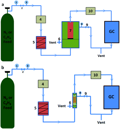
The purification properties of the oxygenated compounds were evaluated by a dynamic adsorption experiment at room temperature. Briefly, the nMSCMs or MSCMs were sealed in a stainless steel module with silicone O-rings for purification measurements, and the leak integrity of the single-channel module was verified by replacing the membrane with a solid stainless steel tube. Before evaluation, full activation of the nMSCMs or MSCMs was achieved by heating at 200 °C for 4 h under high purity N2 flow conditions (100 ml min−1, 0.3 MPa), and then cooled down to room temperature via continuous N2 flow. Subsequently, the N2 or C2H4 feed flow (20 ml min−1, 0.3 MPa) containing at least one trace amount of methanol (20 × 10−6 mol mol−1), dimethyl ether (20 × 10−6 mol mol−1) or propanal (20 × 10−6 mol mol−1) was passed through the nMSCMs or MSCMs from the bottom to the top. At the given time intervals, the impurity content of the permeability gas was analyzed by GC with an online flame ionization detector (FID). A diagram of the purification evaluation experiment is shown in Scheme 3. The pressure of the counterbalance valve was set at 0.5 MPa. The regeneration evaluation experiment was similar to the first evaluation except for the regenerative activation method. In the regeneration experiment, the nMSCMs or MSCMs were activated by two steps: heating up to 120 °C for 1 h, and then heating up to 240 °C for 2 h. Subsequently, N2 or C2H4 feed flow then passed through the regenerated nMSCMs or MSCMs. In the control experiment, MSPs with the same amount of molecular sieves (effective mass about 0.07 g) were loaded in the fixed bed reactor and filled with quartz cottons on the two sides as shown in Scheme 3b. The bed reactor has a length of 10 mm and a diameter of 5 mm. The N2 or C2H4 feed gas was purchased from Shanghai Shenkai Gases Technology Co., Ltd. All experimental data are the average of duplicate determinations, and the relative error is about 0.5%. The cumulative adsorption amount (qt) was calculated according to the following equation:where C0 (10−6 mol mol−1) is the initial concentration of the impurities in feed flow, Ct (10−6 mol mol−1) is the breakthrough concentration of the impurities, t is the breakthrough time of the impurities, m is the 13X molecular sieves weight on the MSPs, nMSCMs or MSCMs, and M is the relative molecular mass of the dimethyl ether, methanol and propanal, respectively. Moreover, 300 (KPa) represents the operating pressure and 1.2 (L h−1) represents the flow rate of N2 or C2H4 feed gas.
3. Results and discussion
3.1 Morphology and structure of MSCMs
As we know, trace amounts of oxygenated compounds, like methanol, dimethyl ether and propanal exist in olefins, and have significant negative effects on olefin polymerization. Thus, it is quite important to remove these impurities before polymerization. Molecular sieve membranes with well-defined sub-nanometer pores, high separation selectivity, low energy consumption and superior thermal, mechanical and anti-corrosive properties could be used as a substitute material for traditional molecular sieve particle adsorbents in the deep removal of the above impurities from olefins. However, it is still quite difficult to provide a new method for preparing 13X molecular sieve membranes with continuous dense and thin molecular sieve layers on the surface of α-Al2O3 tubes. In this study, the present work aimed to design and develop new MSCMs with continuous dense and thin molecular sieve layers combining APTES surface modification and vacuum pre-coating sol technology, and to study their ability to deeply remove impurities from olefins.MSCMs have great potential for the deep removal of oxygenated compounds from olefins because they exhibit the following advantages: firstly, both the α-Al2O3 and 13X molecular sieves are environmentally friendly materials, which do not produce additional toxic effects on the environment; secondly, the tubular membrane structure significantly reduces the mass transfer resistance and increases the contact areas between the impurities and 13X molecular sieves; thirdly, the continuous dense and thin 13X molecular sieve membranes ensure that there are not any non-adsorption interfacial voids decreasing the removal accuracy and breakthrough time; lastly, if the MSCMs serve as replacements for traditional MSPs adsorbents, the regeneration energy consumption and operating costs will be significantly reduced.
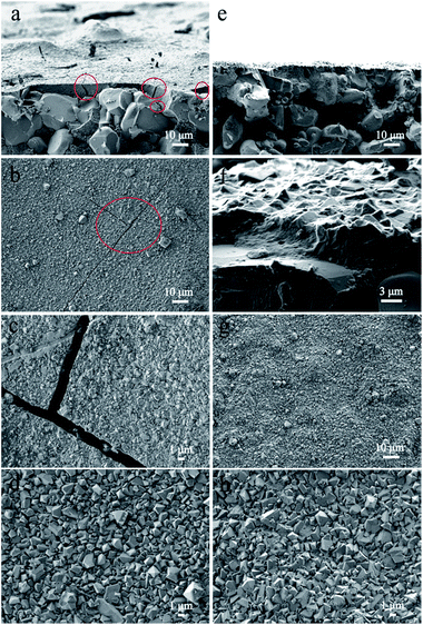
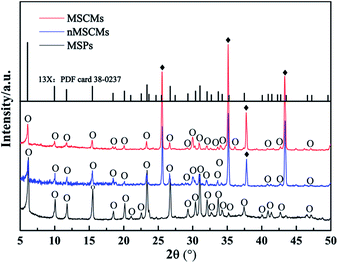
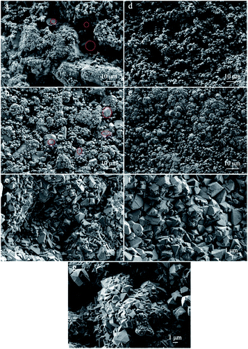
The morphology and structure of the nMSCMs and MSCMs were further investigated by SEM images and XRD patterns. Fig. 1 showed the surface and cross sectional SEM images of the nMSCMs and MSCMs (hydrothermal synthesis at 100 °C for 12 h), respectively. As mentioned in Fig. 1a–d, when using the α-Al2O3 tubes without APTES surface modification for the 13X membrane preparation, we obtained ∼6 μm thick and defect rich molecular sieve layers. These defects mainly contained many transverse and longitudinal cracks (shown by the red circles) with widths of 1.5–2.5 μm (Fig. 1c), which are much higher than the molecular diameter of the impurities. As a result, the existence of these cracks would not be conducive to the deep purification of impurities from olefins, demonstrated by Fig. 3. Moreover, many 13X particles with an average size of 0.8–1.5 μm were uniformly distributed on the membrane surface (Fig. 1d). However, after the α-Al2O3 tubes were modified with APTES (Fig. 1e–h), continuous dense and thin molecular sieve layers without any cracks or other flaws (Fig. 1e–g) were formed on the surface of the α-Al2O3 tubes. The thickness of these continuous molecular sieve membranes was about 5–6 μm (Fig. 1e, f) and the average regular grain size was 0.2–2 μm (Fig. 1h). Notably, we did not find obvious particle aggregation on the surface of either the nMSCMs or MSCMs (Fig. 1b–d and g, h). Fig. 2 depicts the XRD patterns of the MSP, nMSCM and MSCM powders. It showed that all the peaks of the molecular sieve matched well with those of the 13X phase (PDF card 38-0237) on the nMSCMs and MSCMs, except the characteristic peaks of α-Al2O3 at 2θ = 25.556°, 35.185°, 37.901° and 43.333°. Moreover, the XRD patterns of the nMSCMs and MSCMs were not significantly different. The size of 13X crystallites on the nMSCMs and MSCMs was calculated to be about 1.41 μm and 1.52 μm, respectively, according to the Scherrer formula. This result is similar to the SEM conclusion. Likewise, only the characteristic peaks of 13X were detected in the XRD patterns of MSPs. Conceivably, the continuous dense and thin 13X molecular sieve layers without any cracks or other flaws on MSCMs might have more excellent deep purification performance than the nMSCMs.
3.2 Purification evaluation of MSCMs
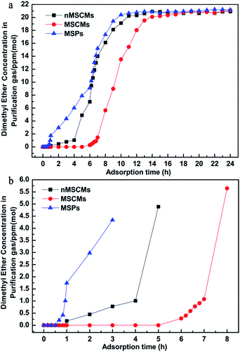
The above comparison showed that the APTES modified porous α-Al2O3 tubes can decisively improve the quality of the resulting 13X molecular sieve membranes. To further evaluate the deep purification property of the MSPs, nMSCMs and MSCMs, a dynamic adsorption experiment was carried out by a feed flow through the adsorbents at room temperature in this study. The operating pressure was maintained at 0.3 MPa and the flow rate was 20 ml min−1. The impurities in the permeation or outlet gas through the pores of the molecular sieve were detected by GC with a FID detector.Dimethyl ether was the first oxygenated impurity that penetrated the samples because of its extremely weak polarity (always considered as a non-polar organic molecule). Hence, it was always used as an indicator to determine whether the adsorption cycle was over. Fig. 3 shows the dimethyl ether adsorption and penetration curves in the N2 system of the MSPs, nMSCMs and MSCMs with the co-existing three oxygenated compounds. It was certainly demonstrated that all of the three materials could deeply purify the dimethyl ether impurity to below 1 × 10⁻⁶ mol mol−1 with the initial concentration of ∼20 × 10−6 mol mol−1 in the N2 feed flow during the competitive adsorption period. However, the nMSCMs and MSCMs had better dimethyl ether deep purification properties than the MSPs. Obviously, compared with the nMSCMs and MSPs, the MSCMs exhibited the best dimethyl ether deep purification properties (Fig. 3b). The breakthrough time of the MSPs, nMSCMs and MSCMs for dimethyl ether were 56 min, 4 h and 7 h, and the accumulated adsorption amounts of the MSPs, nMSCMs and MSCMs for dimethyl ether were 1.662 mg g−1, 5.377 mg g−1 and 12.108 mg g−1, respectively. The longer breakthrough time and higher adsorption amount of dimethyl ether indicated that the MSCMs might have great potential for application in deeply purifying impurities from industrial olefins.
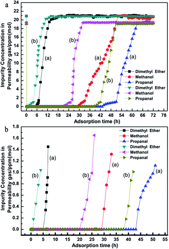
In order to further investigate the deep purification ability for different impurities of the nMSCMs and MSCMs, we used N2 feed flow containing methanol (∼20 × 10−6 mol mol−1), dimethyl ether (∼20 × 10−6 mol mol−1) and propanal (∼20 × 10−6 mol mol−1) as the simulated gas. The further purification results are shown in Fig. 4. Apparently, both of the nMSCMs and MSCMs could deeply purify trace amounts of dimethyl ether, methanol and propanal impurities to below 1 × 10⁻⁶ mol mol−1 from an initial concentration of ∼20 × 10−6 mol mol−1. Fig. 4a and b indicate that the breakthrough times of the nMSCMs for dimethyl ether, methanol and propanal were 4 h, 25 h and 42 h, and the accumulated adsorption amounts for dimethyl ether, methanol and propanal were 7.087 mg g−1, 28.555 mg g−1 and 85.450 mg g−1, respectively. Also, the breakthrough time and the accumulated adsorption amounts of the MSCMs for dimethyl ether, methanol and propanal were 7 h, 32 h, 51 h and 12.108 mg g−1, 35.812 mg g−1, 103.129 mg g−1, respectively. The better deep purification properties of MSCMs compared to that of nMSCMs was mainly attributed to the continuous and integral 13X molecular sieve membranes without non-adsorption interfacial voids. According to the above results, we could further conclude that the MSCMs were more efficient at removing the oxygenated impurities from the gaseous olefins than nMSCMs.
Notably, during the co-adsorption of the three oxygenated impurities the breakthrough times increased in the order: dimethyl ether < methanol < propanal because of the difference in polarity of the oxygenated impurities (polarity order: propanal > methanol > dimethyl ether). It is known that the skeletal negatively charged anions interact with the cations in the 13X molecular sieve structure to form a polar electric field that strongly adsorbs polar-impurities. When the above three oxygenated impurities entered into the molecular sieve pores, the impurities would be adsorbed via the electrostatic action. The stronger the polarity of the impurities, the stronger the binding force would be between the impurities and the pore surface active sites. Therefore, the dimethyl ether first penetrated the 13X molecular sieve membranes and the propanal was the last.
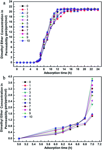
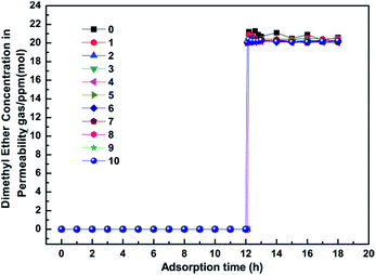
Remarkable adsorbents for industrial application must have excellent purification properties and a long lifetime. Herein, to demonstrate the long-term stability, we investigated the influence of regeneration times on the purification performance during the competitive adsorption period, as shown in Fig. 5. It was noted that the MSCMs had excellent purification properties even after being regenerated 10 times. This result showed that the MSCMs treated by APTES had long-term structure stability, which is beneficial for future industrial applications.
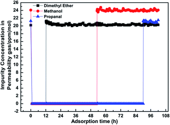
Fig. 6 is the dimethyl ether, methanol and propanal adsorption and penetration curves of the MSCMs in the C2H4 system. Compared with the results in Fig. 4, the MSCMs are better at deeply purifying dimethyl ether, methanol and propanal in the C2H4 system. The breakthrough times for dimethyl ether, methanol and propanal of the MSCMs were 12.1 h, 53 h and 90 h, respectively. Moreover, the accumulated adsorption amounts for dimethyl ether, methanol and propanal were 25.88 mg g−1, 94.19 mg g−1 and 256.26 mg g−1. Notably, there was no obvious co-adsorption of C2H4. The dimethyl ether adsorption and penetration curves of MSCMs with different regeneration times in the C2H4 system are shown in Fig. 7. It was also noted that the MSCMs have excellent purification properties even when regenerated 10 times. Both the N2 and C2H4 purification experiments indicated that the MSCMs are very suitable for deep removal of oxygenated compounds from gaseous olefins.
3.3 Formation mechanism of MSCMs
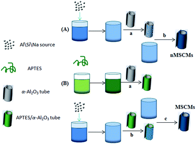
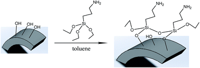
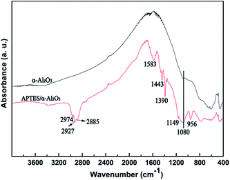
Previous literature has reported that the uniform molecular sieve layers on the surface of the support could be obtained from wet gel or dry gel.40,41 However, in our previous study, we found that the pre-coating sol method was more suitable for the preparation of continuous membranes than the pre-coating gel method. The optimal pre-coating sol conditions were drying in the temperature range 35–45 °C for 12–18 h.42 Non-molecular sieve pores, usually larger than molecular sieve pores, resulting from cracks or other defects in the membranes will significantly reduce the selectivity and purification ability of the gases. Hence, the structural integrity of the molecular sieve layers is quite important. For the purpose of obtaining a continuous dense and thin molecular sieve membrane on the support surface, the coverage of the sol or nucleation layers must be sufficient and homogeneous. However, it still faces a big technical difficulty. The main cause of the cracks or defects was the lack of good adherence between the molecular sieves and the support surface. In order to obtain MSCMs with excellent deep purification performance, we proposed a combination method of APTES surface modification and vacuum pre-coating sol technology to hydrothermally synthesise a continuous dense and thin 13X molecular sieve layer on the surface of porous α-Al2O3 tubes. The preparation process is shown in Scheme 2.In the first stage, the polished porous α-Al2O3 tube was placed in APTES toluene solutions, followed by heating up to 120 °C for 1 h under sealed conditions, resulting in the APTES functionalized porous α-Al2O3 tube (denoted as APTES/α-Al2O3), as shown in Scheme 2B(a). At this stage, the Si–O bonds (ethoxy groups) of the APTES reacted with the surface O–H bonds of the porous α-Al2O3 tubes, which was also confirmed in previous work on highly oriented molecular sieve film fabrication.43 Then a rich layer of APTES was generally assembled on the α-Al2O3 surface (Scheme 2B and Scheme 5). The above result was further demonstrated by a FTIR spectrum of the α-Al2O3 tubes before and after APTES modification as shown in Fig. 8. Compared with the pure α-Al2O3 tubes, many new bands were formed in the FTIR spectrum of the α-Al2O3 tubes after APTES modification. The new band at ∼3381 cm−1 was observed after APTES modification, which indicated the Si–O bonds of the APTES interacted with the surface O–H bonds of the porous α-Al2O3 tubes to form hydroxyl dimers (Scheme 5). The bands at 2927 cm−1 and 2885 cm−1 are symmetrical stretching vibrations of the C–H in the –CH2, the bands at 1583 cm−1 correspond to the N–H surface deformation characteristic absorption peak. However, a weak band at ∼2974 cm−1 was also detected. This result showed that there was still some residual –OCH2CH3 group present during the modification of the α-Al2O3 tubes at 120 °C for 1 h. Moreover, the bands at 1443 cm−1, 1390 cm−1 and 1079 cm−1 are the characteristic peaks of the Si–O stretching vibration. The band at 1149 cm−1 ascribed to the Si–O–Si antisymmetric telescopic vibration and bending vibration were detected, further demonstrating the condensation and crosslinking between the adjacent silane molecules. Similar behaviour was also found in previous research.44,45 The bands at 400–900 cm−1, attributed to the Al–O vibrational absorption band of α-Al2O3, were observed in the α-Al2O3 tubes both before and after APTES modification. The FTIR spectra demonstrated that the APTES was successfully grafted on the surface of the α-Al2O3 tubes. As a result, the surface electronegativity of the porous α-Al2O3 tube changed from negatively charged to nearly neutral under strong alkaline conditions after APTES modification, proved by Fig. 9, which is in accordance with previous literature.34 It was noted that the zeta potentials of the non-APTES treated α-Al2O3 tubes and APTES treated α-Al2O3 tubes were −30.5 and −0.8 mV at pH 11, respectively. This kind of change in electronegativity will minimize the electrostatic repulsion between the negatively charged molecular sieve precursor species and the modified α-Al2O3 tubes.
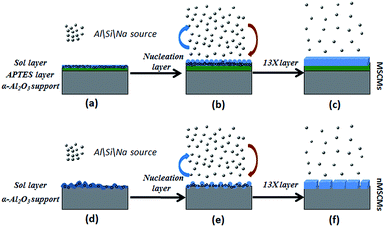 | ||
| Scheme 4 An illustration of the formation mechanism of the MSCMs and nMSCMs: (a–c) MSCMs; (d–f) nMSCMs. | ||
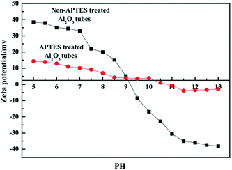 | ||
| Fig. 9 Zeta potential of the non-APTES treated α-Al2O3 tubes and the APTES treated α-Al2O3 tubes suspended in water as a function of pH at room temperature. | ||
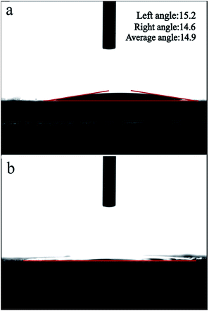
The hydrophilicity/hydrophobicity of the α-Al2O3 tube surfaces, another very important factor, is quite crucial for successful membrane growth. Herein, we used contact angle measurements to determine whether the α-Al2O3 tube surface was hydrophilic or hydrophobic before and after APTES modification. The contact angle measurement results are shown in Fig. 10. Notably, the average contact angle of the non-APTES treated α-Al2O3 tubes was 14.9° and that of the APTES treated α-Al2O3 tubes was nearly 0°. The results demonstrated that the APTES treated α-Al2O3 tubes were more hydrophilic than the non-APTES treated α-Al2O3 tubes. Thus, we could assume that the α-Al2O3 tubes after APTES modification should be able to interact better with the strongly hydrophilic 13X molecular sieve precursor.
In the second stage, the APTES/α-Al2O3 was immersed in the prepared sol solutions with a composition of Al2O3![[thin space (1/6-em)]](https://www.rsc.org/images/entities/char_2009.gif) :
:![[thin space (1/6-em)]](https://www.rsc.org/images/entities/char_2009.gif) 3.5SiO2
3.5SiO2![[thin space (1/6-em)]](https://www.rsc.org/images/entities/char_2009.gif) :
:![[thin space (1/6-em)]](https://www.rsc.org/images/entities/char_2009.gif) 7.88Na2O
7.88Na2O![[thin space (1/6-em)]](https://www.rsc.org/images/entities/char_2009.gif) :
:![[thin space (1/6-em)]](https://www.rsc.org/images/entities/char_2009.gif) 630H2O, and then placed under vacuum with a vacuum degree of 0.005 MPa for 5 s. At this stage, shown in Scheme 2B(b), many molecular sieve precursors were deposited on the α-Al2O3 tubes via electrostatic interactions and covalent bonding (Scheme 4d). After drying at 35 °C for 18 h, more homogeneous sol or nucleation layers covered the surface of APTES/α-Al2O3 tubes compared to the non-APTES treated α-Al2O3 tubes (Fig. 11a, d). Compared with Fig. 11b, the bare surface of the α-Al2O3 tubes was also observed without APTES modification in the red circle. This defect would not benefit the structural integrity of the 13X molecular sieve layers.
630H2O, and then placed under vacuum with a vacuum degree of 0.005 MPa for 5 s. At this stage, shown in Scheme 2B(b), many molecular sieve precursors were deposited on the α-Al2O3 tubes via electrostatic interactions and covalent bonding (Scheme 4d). After drying at 35 °C for 18 h, more homogeneous sol or nucleation layers covered the surface of APTES/α-Al2O3 tubes compared to the non-APTES treated α-Al2O3 tubes (Fig. 11a, d). Compared with Fig. 11b, the bare surface of the α-Al2O3 tubes was also observed without APTES modification in the red circle. This defect would not benefit the structural integrity of the 13X molecular sieve layers.
In the last stage, on one hand, the original 13X crystal nucleus on the outer surface of the sol layers began to grow larger; on the other hand, many new 13X crystal nuclei were gradually formed (Scheme 4d and e and Fig. 11b and e). After the sol-coated α-Al2O3 tubes were placed into the crystallization solutions at 70 °C for 6 h, a dissolution reaction of the dry sol in the solutions occurred. This reaction not only led to the increase of the local ion concentration around the outer region of the sol layers, but also tended to produce sol defects. At the same time, ionization reactions around the sol defect region occurred. The obtained AlO2−, SiO32−, SiO44− and OH− ions might react with Na+ ions to produce 13X particles. As the ionic activity product exceeded the thermodynamic solubility product, the 13X crystals nucleated on the surface of the sol layers using the above defects as active sites. The more homogeneous sol layers existed, the better nucleation layers were obtained, as illustrated in Fig. 11b and e. The bulk crystallization solutions provided abundant nutrients for the crystal growth. With the reaction temperature increasing, the small 13X crystals grew into bigger 13X particles. Finally, a continuous dense and thin molecular sieve membrane was obtained on the surface of the MSCMs (Scheme 4c and Fig. 1e–h). This formation process could be summarized as “solid–solution conversion”. Firstly, formation of homogeneous 13X sol layers; secondly, 13X nucleation by solid–solution transformation; lastly, growth of the 13X crystals. The microstructure of the 13X molecular sieve layers at various reaction times was also investigated. Fig. 11c and f are SEM images of the nMSCMs and MSCMs after hydrothermal synthesis at 100 °C for 6 h, respectively. Interestingly, longitudinal cracks were only observed in Fig. 11c. The XRD patterns in Fig. 12 showed that both nMSCMs and MSCMs remained amorphous after hydrothermal synthesis for 6 h. However, when the reaction time increased to 12 h, continuous dense and thin molecular sieve layers without any cracks or other flaws (Fig. 1e–g) were formed in the MSCMs, and the obtained crystals were pure 13X molecular sieves, except for the characteristic peaks of α-Al2O3. However, when the reaction time further increased to 24 h, many small 13X molecular sieve crystals accumulated to form bigger particles (Fig. 11g).
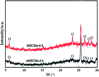 | ||
| Fig. 12 XRD patterns of the nMSCMs and MSCMs after hydrothermal synthesis at 100 °C for 6 h; O-13X molecular sieve. | ||
4. Conclusions
High deep purification performance MSCMs were prepared successfully by a combination of APTES surface modification and vacuum pre-coating sol technology. Like the crystal seed layers, the quality of the dry sol layers plays an important role in improving the 13X molecular sieve formation on porous α-Al2O3 tubes. After hydrothermal synthesis for 12 h at 100 °C, continuous dense and thin 13X molecular sieve layers were formed on the MSCMs without any cracks or other defects, and the thickness of these 13X molecular sieve layers was about 5–6 μm. The formation mechanism of the MSCMs could be summarized as “solid–solution conversion”. The dynamic purification experiment demonstrated that both the nMSCMs and MSCMs could deeply purify trace amounts of methanol, dimethyl ether and propanal to below 1 × 10⁻⁶ mol mol−1 from olefins. But, compared with MSPs and nMSCMs, the MSCMs exhibited the most excellent purification performance. The regeneration experiment also indicated that the MSCMs had long-term structure stability and a long lifetime. The results suggested that the MSCMs have great potential for future industrial application in trace oxygenated compound removal from gaseous olefins.Conflicts of interest
There are no conflicts to declare.Acknowledgements
This work was supported by Shanghai Science and Technology Talent Project (No. 15XD1522300).Notes and references
- C. W. Bradow, D. C. Grenoble, S. N. Milam, B. H. C. Winquist, B. D. Murray and R. M. Foley, U. S. Pat., 6190533, 2001-02-20.
- N. Rahimi and R. Karimzadeh, Appl. Catal., A, 2011, 398, 1 CrossRef CAS.
- J. C. Bricker, Top. Catal., 2012, 55, 1309 CrossRef CAS.
- B. Y. Yu and I. L. Chien, Chem. Eng. Technol., 2016, 39, 2304 CrossRef CAS.
- P. Losch, A. B. Pinar, M. G. Willinger, K. Soukup, S. Chavan, B. Vincent, P. Pale and B. Louis, J. Catal., 2017, 345, 11 CrossRef CAS.
- J. K. Gorawara, H. Rastelli and J. Markovs, U. S. Pat., 5271835, 1993-12-21.
- J. Mcglamery, G. Gerald, J. Beech, H. James, Nicoletti, P. Michael, E. Van and F. Cornelis, U. S. Pat., 7989669, 2011-08-02.
- J. R. Lattner, J. Lumgair and R. David, U. S. Pat., 6838587, 2005-01-04.
- E. Van, F. Cornelis, Wilson and J. David, U. S. Pat., 8309776, 2012-11-13.
- E. Jessy, Trucko, A. Jonathan, Tertel, L. Luigi and R. Javier, U. S. Pat., 9639150, 2015-08-13.
- J. Gorawara, AIChE Spring Meeting and Global Congress on Process Safety [C]//Ethylene Plant Contaminants: Myths and War Stories, AIChE, c2009: 1, Tampa, Florida, America, New York, April, 26–30, 2009 Search PubMed.
- J. Ma, J. Shao, Z. Wang and Y. Yan, Ind. Eng. Chem. Res., 2014, 53, 6121 CrossRef CAS.
- R. W. Baker and K. Lokhandwala, Ind. Eng. Chem. Res., 2008, 47, 2109 CrossRef CAS.
- H. Suzuki, U. S. Pat., 4699892, 1987-10-13.
- Y. Hirota, K. Watanabe, Y. Uchida, Y. Egashira, K. Yoshida, Y. Sasaki and N. Nishiyama, J. Membr. Sci., 2012, 415–416, 176 CrossRef CAS.
- W. J. Koros and R. Mahajan, J. Membr. Sci., 2001, 175, 181 CrossRef.
- Y. Li, J. Liu and W. Yang, J. Membr. Sci., 2006, 281, 646 CrossRef CAS.
- I. G. Wenten, P. T. Dharmawijaya, P. T. P. Aryanti, R. R. Mukti and Khoiruddin, RSC Adv., 2017, 7, 29520 RSC.
- X. R. Wang, Z. Z. Yang, C. L. Yu, L. W. Yin, C. Zhang and X. H. Gu, Microporous Mesoporous Mater., 2014, 197, 17 CrossRef CAS.
- Z. Zong and M. A. Carreon, J. Membr. Sci., 2017, 524, 117 CrossRef CAS.
- L. Wang, C. Zhang, X. C. Gao and X. H. Gu, J. Membr. Sci., 2017, 539, 152 CrossRef CAS.
- S. W. Yang, Z. S. Cao, A. Arvanitis, X. H. Sun, Z. Xu and J. H. Dong, J. Membr. Sci., 2016, 505, 194 CrossRef CAS.
- L. Q. Li, J. H. Yang, J. J. Li, J. Q. Wang, J. M. Lu, D. H. Yin and Y. Zhang, AIChE J., 2016, 62, 2813 CrossRef CAS.
- K. Y. A. Lin, C. H. Wu and A. P. Jochems, J. Mol. Liq., 2017, 232, 269 CrossRef CAS.
- Y. J. Gup, Sep. Sci. Technol., 2011, 46, 1716 CrossRef.
- G. Zhu, Y. Li, H. Zhou, J. Liu and W. Yang, J. Membr. Sci., 2009, 337, 47 CrossRef CAS.
- S. G. Li, V. A. Tuan, J. L. Falconer and R. D. Noble, J. Membr. Sci., 2001, 191, 53 CrossRef CAS.
- R. D. Noble and J. L. Falconer, Catal. Today, 1995, 25, 209 CrossRef CAS.
- S. M. Lee, N. Xu, J. R. Grace, A. W. Li, C. J. Lim, S. S. Kim, F. Fotovat, A. Schaadt and R. J. White, J. Eur. Ceram. Soc., 2018, 38, 211 CrossRef.
- L. Zhang and Y. N. Huang, J. Mater. Chem. A, 2015, 3, 4522 CAS.
- L. Zhang, R. Q. Fu, L. Mathivathanan and A. J. Hernández-Maldonado, Microporous Mesoporous Mater., 2012, 147, 274 CrossRef.
- H. Shi, RSC Adv., 2015, 5, 38330 RSC.
- X. C. Xu, Y. Bao, C. S. Song, W. S. Yang, J. Liu and L. W. Lin, J. Membr. Sci., 2005, 249, 51 CrossRef CAS.
- A. Mundstock, N. Y. Wang, S. Friebe and J. Caro, Microporous Mesoporous Mater., 2015, 215, 20 CrossRef CAS.
- M. G. Barthés-Labrousse, Vacuum, 2002, 67, 385 CrossRef.
- Q. Liu, N. Wang, J. Caro and A. Huang, J. Am. Chem. Soc., 2013, 135, 17679 CrossRef CAS PubMed.
- H. Lee, J. Rho and P. B. Messersmith, Adv. Mater., 2009, 21, 431 CrossRef CAS PubMed.
- D. S. Ling, W. Park, Y. Park II, N. Lee, F. Y. Li, C. Y. Song, S. G. Yang, S. H. Choi, K. Na and T. Hyeon, Angew. Chem., Int. Ed., 2011, 50, 11360 CrossRef CAS PubMed.
- A. Huang, N. Wang and J. Caro, J. Membr. Sci., 2012, 389, 272 CrossRef CAS.
- F. Guillou, L. Rouleau, G. Pirngruber and V. Valtchev, Microporous Mesoporous Mater., 2009, 119, 1 CrossRef CAS.
- K. V. Agrawal, B. Topuz, T. C. T. Pham, T. H. Nguyen, N. Sauer, N. Rangnekar, H. Zhang, K. Narasimharao, S. N. Basahel, L. F. Francis, C. W. Macosko, S. Al-Thabaiti, M. Tsapatsis and K. B. Yoon, Adv. Mater., 2015, 27, 3243 CrossRef CAS PubMed.
- C. X. Zhang, P. F. Wang, H. S. Xu, J. P. Yu, D. Q. Lü, J. A. Xu, S. Wang and F. J. Zhang, Fine Chem., 2017, 34, 858 Search PubMed.
- A. Kulak, Y. Lee, Y. S. Park and K. B. Yoon, Angew. Chem., Int. Ed., 2000, 39, 950 CrossRef CAS PubMed.
- M. Khayet, J. P. G. Villaluenga, J. L. Valentin, M. A. LÓpez-Manchado, J. I. Mengual and B. Seoane, Polymer, 2005, 46, 9881 CrossRef CAS.
- R. Shang, J. Hou, L. Wang, J. S. Yuan and X. S. Wang, Mater. Rev., 2011, 25, 454 Search PubMed.
| This journal is © The Royal Society of Chemistry 2018 |

