 Open Access Article
Creative Commons Attribution 3.0 Unported Licence
Flexible inorganic membranes used as a high thermal safety separator for the lithium-ion battery†
Chuan Shi a,
Jianwei Zhub,
Xiu Shenc,
Fuxing Chena,
Fanggang Ninga,
Hongdi Zhangb,
Yun-Ze Long
 *ab,
Xin Ning*a and
Jinbao Zhao
 c
c
aIndustrial Research Institute of Nonwovens & Technical Textiles, College of Textiles & Colthing, China
bQingdao University, College of Physics Science, China
cXiamen University, Department of Chemical Engineering, China
First published on 23rd January 2018
Abstract
A flexible SiO2 porous fiber membrane (SF) is prepared by electrospinning followed by calcination in this work. Compared with an organic substrate separator, the SF used as a separator will be an absolute guarantee of the battery thermal safety. The porosity of the SF is 88.6%, which is more than twice that of a regular PP separator. Hydrophilic SF shows better electrolyte wetting ability and its high porosity enables the SF to absorb 633% liquid electrolyte on average, while the lithium-ion conductivity reaches 1.53 mS cm−1. The linear sweep voltammogram testing of PP and SF suggested that SF, with great electrochemical stability, can meet the requirements of lithium-ion batteries. The cyclic and rate performances of batteries prepared with SF are improved significantly. Such advantages of the SF, together with its potential in mass production, make the SF a promising membrane for practical applications in secondary lithium-ion batteries.
Introduction
Lithium-ion batteries have been regarded as one of the major power sources for electric vehicles (EVs) and for the storage of new energy in a smart grid due to its high energy density and particularly stable cycle life.1,2 However, the potential safety hazard of the battery is exacerbated with the increase of capacity in current battery construction, in particular the use of separator materials.3–5 The separator is the core component of lithium-ion battery safety as it prevents the direct contact of the cathode and anode, while sustaining the free transport of the lithium-ions in the liquid electrolyte.6,7 Polyolefin porous membranes, particularly polyethylene (PE) and polypropylene (PP) separators became the most widely used products in the field of lithium batteries due to their high mechanical strengths, and excellent chemical and electrochemical stabilities. However, a safety issue, caused by the thermal shrinkage of the polyolefins at higher temperatures, has limited their further applications in energy storage systems, especially in hybrid electric vehicle (HEV) areas.8,9To improve the thermal stability of the separator for the safety of lithium-ion batteries, the polyolefin membranes were modified10–13 and lots of new type of separators14–18 were designed. Among them, the purely inorganic separators prepared with the sintering method could have the advantage of “absolutely” thermal stability, strong electrolyte absorption content and no dendrite puncturing problems.19,20 However, their poor flexibility for cell winding assembly limits their practical application.
Flexible inorganic porous fiber membranes prepared with the electrospinning method were widely studied as insulation, self-cleaning and heat resistant filter.21–25 With high thermal, chemical, electrochemical stabilities and uniform micro–nano pores, they were expected to be a potential candidate as the separator for high safety batteries. In this work, polyvinyl alcohol (PVA) was used as template polymer and silicate (TEOS) was used as the source of SiO2, the PVA/TEOS precursor hybrid fiber membrane was prepared by the electrospinning method. The PVA was removed via high temperature sintering process and the basic inorganic microstructure of the precursor hybrid fiber membrane was retained, leading to flexible SiO2 inorganic porous fiber membrane (SF) materials. Such SF used as separator can guarantee the thermal safety of the batteries. The high porosity of SF obtained via the electrospinning technique allows it to absorb more liquid electrolyte, which further leads to high conductivities, thus improving the cyclic and rate performances of batteries. We believe that these advantages of the SF, together with potential in mass production, make the SF a promising candidate for practical applications in secondary lithium batteries.
Experimental
Materials
The starting materials included poly(vinyl alcohol) (PVA, Mw = 66![[thin space (1/6-em)]](https://www.rsc.org/images/entities/char_2009.gif) 000, Aladdin Shanghai), phosphoric acid (H3PO4; analytical grade, Aladdin Shanghai), tetraethyl orthosilicate (TEOS, Aladdin Shanghai) and deionized water. All materials were purchased commercially without further purification.
000, Aladdin Shanghai), phosphoric acid (H3PO4; analytical grade, Aladdin Shanghai), tetraethyl orthosilicate (TEOS, Aladdin Shanghai) and deionized water. All materials were purchased commercially without further purification.
Preparation of precursor solutions
PVA solution was prepared at mass fraction 10% by dissolving it in the deionized water at 60 °C with vigorous stirring at high rate for 5 h. Silica gel was prepared by hydrolysis and polycondensation by the dropwise addition of H3PO4 into TEOS, then stirring at room temperature for 4 h. The mass ratio of TEOS![[thin space (1/6-em)]](https://www.rsc.org/images/entities/char_2009.gif) :
:![[thin space (1/6-em)]](https://www.rsc.org/images/entities/char_2009.gif) H2O
H2O![[thin space (1/6-em)]](https://www.rsc.org/images/entities/char_2009.gif) :
:![[thin space (1/6-em)]](https://www.rsc.org/images/entities/char_2009.gif) H3PO4 is 1
H3PO4 is 1![[thin space (1/6-em)]](https://www.rsc.org/images/entities/char_2009.gif) :
:![[thin space (1/6-em)]](https://www.rsc.org/images/entities/char_2009.gif) 1
1![[thin space (1/6-em)]](https://www.rsc.org/images/entities/char_2009.gif) :
:![[thin space (1/6-em)]](https://www.rsc.org/images/entities/char_2009.gif) 0.02. Then, 10 g PVA solution was dropped slowly into an equivalent weight of silica sol–gel at room temperature, then stirred for another 5 h. Thus, the viscous precursor solution, used for the electrospinning, was obtained.
0.02. Then, 10 g PVA solution was dropped slowly into an equivalent weight of silica sol–gel at room temperature, then stirred for another 5 h. Thus, the viscous precursor solution, used for the electrospinning, was obtained.
Electrospinning and fabrication of SF
The as-prepared gel was loaded into a syringe and the needle of the syringe was connected to a direct current (DC) high-voltage power source. The grounded stainless steel drum was placed 17 cm from the tip of the needle as the collector wrapped with aluminum foil and rotated at 40 rpm. The feeding rate of the precursor solutions by the syringe pump was 1 mL h−1. The fabrication chamber was kept at constant temperature (25 °C) and relative humidity (45%). An electric potential of 18 KV between the needle and the stainless steel drum was applied by the high-voltage power source and the hybrid nano-fibrous membranes were obtained on the aluminum foil. The hybrid nano-fibrous membranes were with heated at a temperature increase rate of 2 °C min−1 in the air until it reached 600 °C and maintained for 2 h to remove the organic constituents of PVA, the SF was obtained after being cooled down to room temperature.Electrode preparation and cell assembly
Coin cells were prepared for battery performance tests. A mixture of slurry containing 5 wt% acetylene black (super-P), 5 wt% polyvinylidene fluoride (PVDF) and 90 wt% LiMn2O4 (Qingdao Xinzheng Material Co., Ltd, China) in N-methyl pyrrolidine (NMP) was prepared for cathode of the cells. The PP separator (Nantong Tianfeng New Electronic Materials Co., Ltd.) and SF were used as separators for preparing the batteries. Batteries after injected by the equivalent weight of electrolyte (1 mol L−1 LiPF6 dissolved in a mixed solution of dimethyl carbonate (DMC), ethylene carbonate (EC) and diethylcarbonate (DEC) with a volume ratio of 1![[thin space (1/6-em)]](https://www.rsc.org/images/entities/char_2009.gif) :
:![[thin space (1/6-em)]](https://www.rsc.org/images/entities/char_2009.gif) 1
1![[thin space (1/6-em)]](https://www.rsc.org/images/entities/char_2009.gif) :
:![[thin space (1/6-em)]](https://www.rsc.org/images/entities/char_2009.gif) 1) were assembled in the argon gas within a glove box (Mbraun, Germany).
1) were assembled in the argon gas within a glove box (Mbraun, Germany).
Characterization of the separators
The surface morphologies of pure PP separator and SF were investigated by (Phenom pro, Netherlands) at the acceleration voltage of 10 kV. Bruker AVANC III was used for the solid state NMR spectrometer test. Instron 3300 with a speed of 5 mm min−1 was used for the mechanical strength test. The porosity of the SF and PP separator can be calculated by the following equation with the n-butanol uptake method:| P% = MBuOH/(ρBuOH × (MBuOH/ρBuOH + Mm/ρP)) × 100% |
A commercial drop shape analysis system (Powereach JC2000C1, Shanghai Zhongchen Digital Technique Equipment Co. Ltd., China) was used for the static contact angles text of PP separator and SF. The electrolyte uptake of the membranes was calculated by the following equation:
| Uptake (%) = (W − W0)/W0 × 100% |
The ionic conductivities of PP separator and SF absorbing liquid electrolyte and sandwiched between two stainless steel electrodes were investigated by an electrochemical workstation (Solartron, SI-1260, England) with the frequency range of 1 kHz to 100 kHz.
Cells with PP separator and SF were prepared to investigate the cyclic and rate performance using the electrochemical test equipment (LAND-V34, Land Electronic, China). To study the cyclic performances of the batteries, the cells were charged to 4.2 V and discharged to 3 V at 1.0C and the rate performance tests were carried out at current rates of 0.5C, 1.0C, 2.0C, 5.0C, 10.0C and 0.5C.
Results and discussion
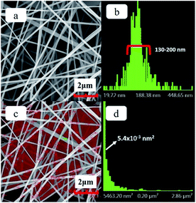
The SEM images of the precursor hybrid fiber membrane and the distributions of fiber diameter and pore size are shown in Fig. 1. It can be seen from the figure that the surface fibers of the hybrid fiber membrane prepared by the electrospinning process is smooth and straight. The fiber diameter distribution chart (Fig. 1b) shows that the diameter of fibers has a concentrated distribution between a narrow range of 130–200 nm, manifesting good quality of the fineness of fibers. The pore size of the hybrid fiber membrane is formed by the random layout of the fibers. After disregarding the incomplete pores at the edges of the image, the pore size distribution of hybrid fiber membranes is calculated (as shown in Fig. 1c and d). The pore size is concentrated at 0.05 μm2, albeit this, there still exist pores with sizes larger than 3.00 μm2.The PVA component in the precursor hybrid fiber membrane was removed via high temperature sintering process to prepare the SF membrane. The SEM image of the SF and the distributions of the fiber diameter and pore size are shown in Fig. 2. It can be seen from Fig. 2a that the SF prepared by the sintering process retains the microstructure of the hybrid fiber membrane fairly well, with smooth fiber surface and uniform fiber fineness. Compared with the hybrid fiber membrane, fibers of SF are slightly curved. According to the fiber diameter chart (Fig. 2b), the diameters of the inorganic fibers are mainly between 150–300 nm. The average diameter of the inorganic fiber increased after the sintering process, suggesting that the fiber itself would undergo a physical changes such as nano-void formation during the sintering process, rather than a theoretical reduction in size due to the loss of the PVA composition in the fiber mass. Fig. 2c and d, also show that the pore size of the SF is concentrated at 0.04 μm2, with more pores having a size between 0.04 μm2 to 0.30 μm2 and less pores having a size above 1.5 μm2. The highly localized distribution of pore size indicate more uniformity in the pore sizes, which accompanies the physical changes of the fibers. Pore size uniformity is desirable and will contribute to the uniformity of the current in the lithium-ion battery and improves the performance of lithium-ion battery. As shown in the Fig. S1,† the pure PP separator shows an interconnected submicron porous structure which is a typical morphology from the dry process. In comparison, the pores of SF formed by the direct accumulation of fibers are large, which together with individual fiber characteristics, may be more conducive to absorbing liquid electrolyte and to the rapid conduction of Li+.26,27
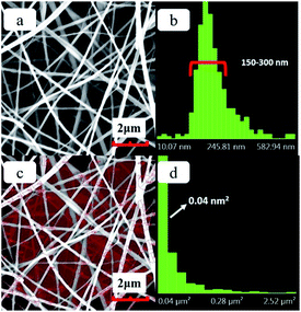 | ||
| Fig. 2 (a) SEM image of the SF, (b) the fiber diameter distribution chart of SF, (c) the area of SF pore size distribution statistics (d) the pore size distribution chart of SF. | ||
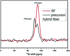
The NMR of the SF and precursor hybrid fiber were shown in Fig. 3. It can be seen from Fig. 3, precursor hybrid fiber possess characteristic peaks of silicate species and silica. This shows that during the preparation of hybrid fiber membranes, TEOS has been partially hydrolyzed to silicic acid and silica, and the concentration of silicate is higher than that of silica.28 The NMR spectrum of SF was consistent with that of silica, indicating that TEOS completely hydrolyzed to SiO2 after calcined at high temperature, and finally the pure inorganic SiO2 nanofiber membrane was obtained. We also tested the mechanical strength of SF. The relevant data is in the Fig. S2.† The PP separator prepared with uniaxial stretching process will result in a significant mechanical strength decrease in this direction. Experiments show that even compared with the uniaxial stretching direction of the PP separator 7.5 MPa, the tensile strength of SF 3.5 MPa was still much lower. Obviously, the tensile strength of SF cannot fully meet the practical applications needs and we are currently also looking for ways to improve its mechanical strength.
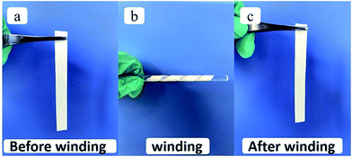
Good separator material flexibility is critical in battery manufacturing, which requires flexibility for assembly processes in both pouch and cylindrical cell configurations.29 As shown in Fig. 4, the SF is coiled around a glass rod to illustrate its good flexibility and can also recover the smooth morphology after winding.
The SF obtained after the high temperature sintering process could have the advantages of “absolute” thermal stability. To test the thermal stability of the separator under more severe conditions, the separators were ignited by a direct flame of a lighter and the results were shown in Fig. 5. The PP separator burned up immediately and was completely decomposed in just 1 s. The morphologies and the flexibility of SF showed negligible changes in 1 min. This flame-resistant properties of the SF are very useful for improving the thermal stability of lithium-ion batteries.
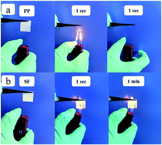 | ||
| Fig. 5 The thermal stability test of the (a) PP at 1 second and (b) SF separator at 1 second and 1 minute. | ||
Separator and liquid electrolyte with good wettability can effectively sustain the electrolyte solution, and thus facilitate the lithium-ion transport between the cathode and the anode.30,31 Therefore, the wettability of the separator with the liquid electrolyte plays an important role in battery performance. The time dependence of the contact angle between the surface of the electrolyte and the separator surface reflects the wettability of the separator, which was measured and showed in Fig. 6. A high contact angle implies low wettability. As per the conventional/general procedure, a drop of the electrolyte was deposited on the separator surface, and the time-dependent contact angle was measured. As shown in Fig. 6, the contact angle for the PP separator was 70.0° at 1 s and decreased to 55° at 10 s. In contrast, the SF has a contact angle as small as 32° at 1 s and further decreased to below 10° at 10 s, indicating significant improvement in the wettability of the SF with the electrolyte.
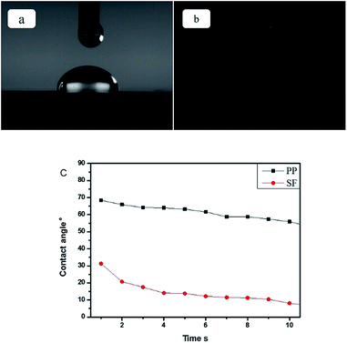 | ||
| Fig. 6 (a) Contact angle for PP separator at 1 s, (b) contact angle for SF separator at 1 s, (c) contact angle of the separators changes with the time. | ||
A separator with high porosity and high liquid electrolyte uptake can retain more electrolyte and improve better ion transport. The porosity, electrolyte uptake and the ionic conductivity of PP and SF separators were measured and summarized in Table 1. The porosities of PP and SF are 43.6% and 88.6% respectively. The porosity of SF is nearly twice that of the PP. The electrolyte uptakes of PP and SF membranes are 62.9% and 633% respectively. The electrolyte uptake of SF is more than 10 times of the PP. SF having less weight and higher porosity results in a significant increase of the liquid electrolyte uptake. The ionic conductivities of PP separator and SF after soaking in the electrolyte solution are 0.80 mS cm−1 and 1.58 mS cm−1. The ionic conductivity of SF is nearly double the PP. The high porosity and high uptake of liquid electrolyte of SF is beneficial to increasing the ionic conductivity. High electrolyte uptake and ionic conductivity also help improve the cyclic and rate performance of lithium-ion batteries.
| Separator | PP separator | SF |
| Thickness μm | 40 | 45 |
| Porosity% | 43.6 | 80.0 ± 0.5 |
| Average uptake% | 62.9 ± 6 | 633 ± 10 |
| Ionic conductivity mS cm−1 | 0.80 ± 0.01 | 1.58 ± 0.03 |
To achieve the practical application as lithium-ion battery separator, it is important to investigate the electrochemical stability of the separator in the lithium-ion battery system. The linear sweep voltammograms (LSV) test of PP and SF with Li and stainless steel electrode were used to demonstrate the electrochemical stability of separator and Fig. 7 displayed the LSV result. PP separator shows obvious decomposition at about 4.8 V. Compared with the PP separator, the SF separator shows no obvious decomposition below 5 V, suggesting great electrochemical stability and it can meet the requirements of lithium-ion battery.
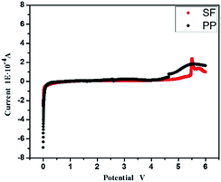 | ||
| Fig. 7 The linear sweep voltammograms of PP and SF with Li and stainless steel electrode from 0 V to 6 V. | ||
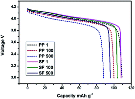
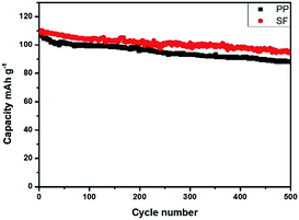
Cells were charged and discharged for 500 cycles from 3.0 to 4.2 V at 1C rate for the cyclic performance test. Battery performances with PP and SF separators were shown in Fig. 8 and 9. As can be seen in Fig. 8, the traditional LiMn2O4 batteries discharge curve of PP and SF are almost the same, means there is no side effect for the use of SF membrane. Upon cycling, the LiMn2O4 cathode with PP separator and SF separator exhibited a high specific capacity of 110 mA g−1 at the first cycle and was stabilized above 500 cycles. The battery retained 87.5% capacity with SF separator and 80.5% with PP separator after 500 cycles. The improvement in cyclic performance of battery with SF separator was associated with the high electrolyte uptake and better wettability of the separator with the electrolyte.
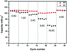
Batteries were charged and discharged at the rates of 0.5C, 1.0C, 2.0C, 5.0C, 10.0C and 0.5C for the rate performance test. As the Fig. 10 showed, the discharge capacities of batteries with PP separator and SF separator decreased gradually with the increase in rate. The capacity of the batteries displayed no big difference in low rate and batteries prepared with SF showed higher rate capacity at high rate. The improvement in rate performance of battery was associated with the high electrolyte uptake and ionic conductivity of SF separator.
Conclusions
The SF can maintain the stability of the nano-porous structure even when it is ignited. The as-prepared SF used as separator can significantly enhance the thermal safety of the batteries which is critical for the development of electric vehicles and energy storage system. The porosity, electrolyte uptake and lithium-ion conductivity of the SF is 88.6%, 633% and 1.53 mS cm−1, which are much higher than those of the PP separator, resulting in improved cyclic and rate performances of batteries. Such functional advantages, together with the potential for mass production, makes SF suitable for practical applications in secondary lithium batteries.Conflicts of interest
There are no conflicts to declare.Acknowledgements
This work was supported by the National Natural Science Foundation of China (51373082 and 51673103), the Taishan Scholars Programme of Shandong Province, China (ts20120528), and the Shandong Provincial Key Research and Development Plan (2016GGX102011).References
- K. Brandt, Solid State Ionics, 1994, 69, 173–183 CrossRef CAS.
- G. Wu, H. Wu, K. Wang, C. Zheng, Y. Wang and A. Feng, RSC Adv., 2016, 6, 58069–58076 RSC.
- S. I. Tobishima and J. I. Yamaki, J. Power Sources, 1999, 81–82, 882–886 CrossRef CAS.
- J. Hassoun, S. Panero, P. Reale and B. Scrosati, Adv. Mater., 2009, 21, 4807–4810 CrossRef CAS PubMed.
- P. G. Balakrishnan, R. Ramesh and T. Prem Kumar, J. Power Sources, 2006, 155, 401–414 CrossRef CAS.
- S. S. Zhang, J. Power Sources, 2007, 164, 351–364 CrossRef CAS.
- P. Arora and Z. Zhang, Chem. Rev., 2004, 104, 4419–4462 CrossRef CAS PubMed.
- D. Takemura, S. Aihara, K. Hamano, M. Kise, T. Nishimura, H. Urushibata and H. Yoshiyasu, J. Power Sources, 2005, 146, 779–783 CrossRef CAS.
- K. J. Kim, J.-H. Kim, M.-S. Park, H. K. Kwon, H. Kim and Y.-J. Kim, J. Power Sources, 2012, 198, 298–302 CrossRef CAS.
- C. Shi, P. Zhang, L. Chen, P. Yang and J. Zhao, J. Power Sources, 2014, 270, 547–553 CrossRef CAS.
- C. Shi, J. Dai, X. Shen, L. Peng, C. Li, X. Wang, P. Zhang and J. Zhao, J. Membr. Sci., 2016, 517, 91–99 CrossRef CAS.
- M.-H. Ryou, D. J. Lee, J.-N. Lee, Y. M. Lee, J.-K. Park and J. W. Choi, Adv. Energy Mater., 2012, 2, 645–650 CrossRef CAS.
- D. Fu, B. Luan, S. Argue, M. N. Bureau and I. J. Davidson, J. Power Sources, 2012, 206, 325–333 CrossRef CAS.
- X. Zhou, L. Yue, J. Zhang, Q. Kong, Z. Liu, J. Yao and G. Cui, J. Electrochem. Soc., 2013, 160, A1341–A1347 CrossRef CAS.
- J. Zhang, L. Yue, Q. Kong, Z. Liu, X. Zhou, C. Zhang, S. Pang, X. Wang, J. Yao and G. Cui, J. Electrochem. Soc., 2013, 160, A769–A774 CrossRef CAS.
- L. C. Zhang, Z. Hu, L. Wang, F. Teng, Y. Yu and C. H. Chen, Electrochim. Acta, 2013, 89, 310–316 CrossRef CAS.
- D. T. Wong, S. A. Mullin, V. S. Battaglia and N. P. Balsara, J. Membr. Sci., 2012, 394–395, 175–183 CrossRef CAS.
- J. Hao, G. Lei, Z. Li, L. Wu, Q. Xiao and L. Wang, J. Membr. Sci., 2013, 428, 11–16 CrossRef CAS.
- J. Chen, S. Wang, D. Cai and H. Wang, J. Membr. Sci., 2014, 449, 169–175 CrossRef CAS.
- H. Xiang, J. Chen, Z. Li and H. Wang, J. Power Sources, 2011, 196, 8651–8655 CrossRef CAS.
- H. Yu, J. Guo, S. Zhu, Y. Li, Q. Zhang and M. Zhu, Mater. Lett., 2012, 74, 247–249 CrossRef CAS.
- P. Milanović, M. Dimitrijević, R. Jančić Heinemann, J. Rogan, D. B. Stojanović, A. Kojović and R. Aleksić, Ceram. Int., 2013, 39, 2131–2134 CrossRef.
- X. Mao, Y. Si, Y. Chen, L. Yang, F. Zhao, B. Ding and J. Yu, RSC Adv., 2012, 2, 12216 RSC.
- Z. Ma, H. Ji, D. Tan, Y. Teng, G. Dong, J. Zhou, J. Qiu and M. Zhang, Colloids Surf., A, 2011, 387, 57–64 CrossRef CAS.
- Y. Si, X. Mao, H. Zheng, J. Yu and B. Ding, RSC Adv., 2015, 5, 6027–6032 RSC.
- C. Shi, P. Zhang, S. Huang, X. He, P. Yang, D. Wu, D. Sun and J. Zhao, J. Power Sources, 2015, 298, 158–165 CrossRef CAS.
- W. Chen, Y. Liu, Y. Ma and W. Yang, J. Power Sources, 2015, 273, 1127–1135 CrossRef CAS.
- M. Lin, X. Shu, X. Wang, Q. Zhao, X. Han, L. Lin and X. Bao, Chin. J. Catal., 1999, 20 Search PubMed.
- K. Liu, W. Liu, Y. Qiu, B. Kong, Y. Sun, Z. Chen, D. Zhuo, D. Lin and Y. Cui, Sci. Adv., 2017, 3 Search PubMed.
- J.-Y. Sohn, J.-S. Im, J. Shin and Y.-C. Nho, J. Solid State Electrochem., 2011, 16, 551–556 CrossRef.
- S.-J. Gwon, J.-H. Choi, J.-Y. Sohn, Y.-M. Lim, Y.-C. Nho and Y.-E. Ihm, J. Ind. Eng. Chem., 2009, 15, 748–751 CrossRef CAS.
Footnote |
| † Electronic supplementary information (ESI) available. See DOI: 10.1039/c7ra13058a |
| This journal is © The Royal Society of Chemistry 2018 |

