 Open Access Article
Eco-friendly synthesis of graphene–chitosan composite hydrogel as efficient adsorbent for Congo red†
Sakineh Omidi and
Ali Kakanejadifard *
*
Faculty of Science, Department of Chemistry, Lorestan University, Khorramabad, Iran. E-mail: ali.kakanejadifard@gmail.com
First published on 28th March 2018
Abstract
A simple approach was utilized to synthesize graphene/chitosan-based hydrogel using glutaraldehyde as crosslinking agent in room temperature. The composite aerogel was used for removal of cationic and anionic dyes from aqueous solution. It showed high adsorption capacity towards Congo red as an anionic dye. Adsorption experiments were performed based on various parameters, such as initial Congo red concentration, solution pH and contact time. The kinetics data were analyzed using four different models and the pseudo-second-order model best described the adsorption of Congo red aerogel. The Equilibrium adsorption isotherm data indicated that equilibrium data were fitted to the Langmuir isotherm. The maximum dye adsorption capacity calculated from the Langmuir isotherm equation was 384.62 mg g−1. Moreover, the aerogel was stable and easily recovered, and adsorption capacity was about 100% of the initial saturation adsorption capacity after being used three times.
Introduction
The discharge of waste from different dye-related industries into the water stream has been considered as a major environmental issue.1,2 Congo red (CR), an anionic diazo dye, is one of the most important azo dyes. It is highly soluble in aqueous solution and resistant to microbial biodegradation and photocatalysis due to its complex and stable aromatic molecular structure. CR is metabolized into benzidine which is a suspect carcinogen and mutagen compound.3,4 Many forms of carbon-based materials were used as the adsorbent for water purification, such as conventional activated carbon,5 carbon nanomaterials, including carbon nanotubes,6 and carbon nanofibers.7 Graphene, a single layer of two-dimensional carbon lattice, has attracted intensive interest because of its excellent mechanical, physical and chemical properties.8,9 Graphene-based materials have widespread applications in many technological fields including nanoelectronic devices,10 hydrogen storage,11 drug delivery12 and antibacterial.13,14 Graphene exhibits huge specific surface area with a theoretical value of 2630 m2 g−1 (ref. 15) that make it a possible candidate as dye adsorbent. Pristine graphene is hydrophobic substance and it is not a good adsorbent for many types of pollutions. Graphene oxide (GO) contains various functional groups such as hydroxyls and carboxyls in the plane or at the edge. Therefore, GO is hydrophilic and has a negative charge that could be attached to heavy metals ions16 and positively charged organic compounds.17To utilize of the large surface area, much effort has been devoted to the preparation of the stable homogeneous dispersion of single-layered GO as an absorbent.18 However, high water dispersibility of GO caused that expensive separation techniques such as ultrahigh centrifugation be essential to remove the spent GO after the adsorption process. Furthermore, since GO is a nano-material and unprecipitated GO can exhibit potential toxicity to human cells,19,20 the public is concerned on their ecological and environmental risks. As a result, the practical applications of nano-dispersed GO in wastewater purification may restrict. An appropriate absorbent should have the high surface area, easy recovery, and excellent stability. Construction of graphene-based three-dimensional (3D) is a facile strategy, to achieve a good absorbent with useful properties such as large surface areas, ultralow density, easy separation and strong mechanical strength.21 GO-based hydrogels with enhanced absorption capability has been previously reported.22,23
Chitosan is a non-toxic, biodegradable and biocompatible polysaccharide. Several researchers have reported the graphene or chitosan composite hydrogels as efficient adsorbents for water purification. Chatterjee investigated the adsorption performance of chitosan (CS) hydrogel beads impregnated with nonionic and anionic surfactants,24 cetyl trimethyl ammonium bromide25 and multiwalled carbon nanotubes26 for the removal of Congo red (CR) from aqueous solution. Li and Bai report an eco-friendly graphene oxide–chitosan (GO–CS) hydrogel as a broad-spectrum adsorbent for deletion of dyes and metal ions.27 Shang synthesized Konjac glucomannan–graphene oxide hydrogel and used it to adsorb methyl orange and methyl blue in aqueous solutions.28 Cheng and Zhao successfully prepared GO-biopolymer gels with bovine serum albumin, DNA, and chitosan as adsorbent for cationic dyes and metal ions.29 These and many other reports30–40 indicated that chitosan and graphene-based material have potential utility for construction of composite material as efficient adsorbents. Some recent review articles have highlighted the application of graphene oxide nitrogen-containing derivatives or graphene 3D structures in removal of contaminants from wastewater.41,42
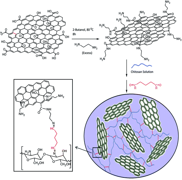
In this research, first GO was converted to an aminated form with ethylenediamine (EDA). Unlike GO, the aminated-graphene (GN) has a positive surface charge and is expected to be a good adsorbent for anionic dyes. Upon adding glutaraldehyde (Glu) to the mixture of GN and chitosan (CS), the (GN–CS) hydrogel was generated rapidly. The hydrogel can simply be turned into GN–CS aerogel by freeze-drying. The aerogel was tested to remove cationic and anionic dyes from aqueous solution. After the adsorption process the GN–CS aerogel is recovered by filtration or decantation. Kinetics and isothermic models were investigated to best describe the adsorption process.
Experimental
Chemicals
All solvents and chemical reagents were purchased from Merck and Sigma-Aldrich companies. The solvents used in the reactions were analytically reagent grade. For UV-Vis experiments the purity grade solvents (>99.9%), were used without any additional purification. GO was prepared according to an improved method.43Instruments
FT-IR spectra were registered on a Shimadzu 8400S spectrometer using KBr disc. The UV-Vis spectra were recorded with a Shimadzu 1650 spectrophotometer. Patterns of X-ray diffraction of the materials were recorded by a Halland Philips X-ray Powder Diffraction (XRD) diffractometer at a scanning speed of 2° min−1 from 10° to 100° (CuK, radiation, λ = 0.154056 nm). Structure and morphology of the nanomaterials were identified using an LEO 440i Field Emission Scanning Electron Microscope (FE-SEM) under vacuum at an operating voltage of 10 kV. Energy-dispersive X-ray microanalysis (EDX) system was used to discover corresponding elements atomic numbers. Zeta potential measurements were carried out using a Nanotrac wave II Q Particle Size Analyzer equipped with a diode laser operating at 780.0 nm.Synthesis of aminated-GO (GN)
GN was prepared from GO according to the method reported with a few modifications.44,45 In a typical experiment, 0.5 g GO was spread in 50 mL 2-butanol and sonicated for 60 min to give a uniform brown colloidal solution. The dispersed solution was added slowly over a period of two hours to 10.0 mL of EDA. The excess EDA prevents cross-linking of graphene sheets. The mixture was heated to 80–85 °C and stirred for 8 h. Then it was cooled down to room temperature and centrifuged (6000 rpm for 10 min). The residual solid material was washed with ethanol and centrifuged again (two times). The resultant solid was dried at room temperature.Preparation of GN–CS hydrogel
A CS standard solution with a concentration of 1.5% w/v was prepared in 100.0 mL of 2% (v/v) aqueous acetic acid, and stirring (450 rpm) overnight to obtain homogeneity. The pH of solution adjusted at 4.0 using dilute sodium hydroxide. A 3% w/v of GN solution was prepared by dispersing of 0.3 g GN in 10.0 mL distilled water and sonicated for 60 min. 1.0 mL CS solution was added to 1 mL of GN suspension, and the mixtures were stirred for 5 min. Under intense stirring, glutaraldehyde was added into the mixture. The gelation occurred within about 60 s of stirring. The obtained hydrogel was washed with deionized water, then it freeze-dried overnight to get an aerogel and preserved for further applications.Swelling investigations
Swelling capacity of GN–CS hydrogel was examined by immersing 1.5 g of wet synthesized GN–CS hydrogel into 200.0 mL of distilled water at 25 °C for 24 hours. The swollen hydrogel was then decanted and excess water removed from surface of hydrogel and weight. The swollen GN–CS hydrogel dried at 60 °C then weighted. The adsorption capacity was calculated using eqn (1).
 | (1) |
Adsorption experiments
The dye adsorption capacity was examined by placing the aerogel in aqueous dye solutions. Before adsorption process the aerogel washed with distilled water until pH of supernatant reached around 7.0. The effects of different parameters such as pH (4.0–10.0), initial dye concentration (5.0–500.0 mg L−1) and contact time were studied. In a typical experiment, the optimized amount of hydrogel was added into 30.0 mL aqueous solution of dye solutions with determined concentration. The mixture was stirred at a speed of 300 rpm at 25 °C. At predetermined time intervals, 2.0 mL of sample was separated and concentrations of solutions were measured with a UV-Vis spectrophotometer at 497 nm and 530 nm for CR solution with pH = 7.0, 10.0 and pH = 4.0 respectively, and the absorbance at 603 nm for JB solution with pH = 7.0. The percent removal (R%) of dye and the adsorption capacity (qe) of the hydrogel in batch adsorption experiment were calculated using eqn (2) and (3) respectively.
 | (2) |
 | (3) |
The kinetic experiments were carried out at pH = 7.0. 15.0 mg of the GN–CS aerogel was added to 30.0 mL of the CR solution (concentration: 20.0 mg L−1) contained in a 100.0 mL beaker at room temperature. Samples of 2.0 mL volume were withdrawn from the reaction mixture at a pre-fixed time interval. The adsorbent particles were separated out by decantation of solution and examined for residual CR concentration using a UV-Vis spectrophotometer at λmax = 497 nm. Isotherm studies were performed in a similar condition to the kinetic experiments and varying initial CR concentration of 100.0–500.0 mg L−1.
Results and discussion
After successful synthesis of GN–CS aerogel, it was characterized using various techniques including FT-IR, XRD, FE-SEM and EDX spectroscopy. GN–CS aerogel has a porous structure, so this 3D nanostructure provided enough space to absorbed many types of contaminations. Scheme 1 shows the general preparation procedure of the GN–CS hydrogel.Characterization of GN–CS hydrogel
Fig. 1a displays the FT-IR spectra of GO, GN, CS, Glu, and GN–CS aerogel solid samples. The FT-IR spectrum of GO showed the bands of hydrogen bonded O–H (3100–3600 cm−1), C![[double bond, length as m-dash]](https://www.rsc.org/images/entities/char_e001.gif) O (1731 cm−1), C
O (1731 cm−1), C![[double bond, length as m-dash]](https://www.rsc.org/images/entities/char_e001.gif) C (1623 cm−1) and C–O (1222 cm−1, 1053 cm−1). In GN spectrum a significant drop in strength of the band at 1731 cm−1 was identified compared to original GO. The occurrence of two new bands at 1635 cm−1 (C
C (1623 cm−1) and C–O (1222 cm−1, 1053 cm−1). In GN spectrum a significant drop in strength of the band at 1731 cm−1 was identified compared to original GO. The occurrence of two new bands at 1635 cm−1 (C![[double bond, length as m-dash]](https://www.rsc.org/images/entities/char_e001.gif) O of the amide bond) and 1361 cm−1 (C–N) in the spectrum of GN indicate the complete grafting of EDA on the GO surface.44 FT-IR spectrum of chitosan, showed the absorption bands at 3360 cm −1 (O–H and N–H), 2922 cm −1 and 2877 cm −1 (aliphatic C–H), 1655 cm −1 (bending vibration N–H), 1379 cm −1 (C–N), and 1078 cm −1 (C–O). FT-IR spectrum of glutaraldehyde showed the absorption bands at 3354 cm −1 (O–H of H2O), 2951 cm −1 (aliphatic C–H), 2870 cm −1 and 2737 cm −1 (H–CO) and 1718 cm −1 (HC
O of the amide bond) and 1361 cm−1 (C–N) in the spectrum of GN indicate the complete grafting of EDA on the GO surface.44 FT-IR spectrum of chitosan, showed the absorption bands at 3360 cm −1 (O–H and N–H), 2922 cm −1 and 2877 cm −1 (aliphatic C–H), 1655 cm −1 (bending vibration N–H), 1379 cm −1 (C–N), and 1078 cm −1 (C–O). FT-IR spectrum of glutaraldehyde showed the absorption bands at 3354 cm −1 (O–H of H2O), 2951 cm −1 (aliphatic C–H), 2870 cm −1 and 2737 cm −1 (H–CO) and 1718 cm −1 (HC![[double bond, length as m-dash]](https://www.rsc.org/images/entities/char_e001.gif) O). In the FT-IR spectrum of GN–CS, the presence of absorbance bands at 1645 cm −1 indicated the formation of imine linkage. This spectrum also showed the absorption bands at 3400 cm −1 (O–H), 2943 cm −1 and 2871 cm −1 (aliphatic C–H), 1357 cm −1 (C–N), and 1112 cm −1, 1024 cm −1 (C–O).
O). In the FT-IR spectrum of GN–CS, the presence of absorbance bands at 1645 cm −1 indicated the formation of imine linkage. This spectrum also showed the absorption bands at 3400 cm −1 (O–H), 2943 cm −1 and 2871 cm −1 (aliphatic C–H), 1357 cm −1 (C–N), and 1112 cm −1, 1024 cm −1 (C–O).
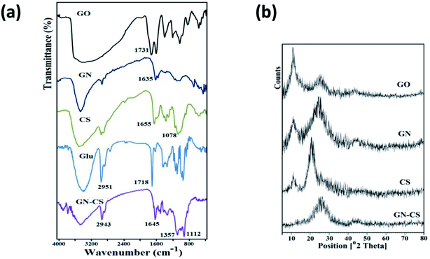 | ||
| Fig. 1 (a) FT-IR spectra of GO, GN, CS, Glu, and GN–CS. (b) The XRD patterns of GO, GN, CS and GN–CS. | ||
XRD patterns of the GO, GN, CS, and GN–CS, between 10° and 80°, are shown in Fig. 1b. The specific 2θ peak of GO at 10.74° corresponds to (0 0 1) interplanar spacing of 0.822 nm. In the case of GN, the intense (0 0 1) peak decreased, while broad diffraction peaks appear at 2θ = 25.4°, corresponding to the interplanar spacing of 0.35 nm, which attributed to the (0 0 2) peak of graphite. Chitosan shows two peaks at 2θ = 10.75°, and 2θ = 21.2° corresponding to crystalline structure and amorphous state of chitosan, respectively.46 GN–CS indicated only a broad peak between 2θ = 20–30°. This peak is like to that of GN, consequential from the remainder stacked GN sheets in the composite. The characteristic peaks of chitosan are not detected in the XRD patterns of GN–CS aerogel, showing that CS chains are well spread on the GO sheets. The absence of the diffraction peak at 2θ ≈ 10.75° in XRD pattern of GN–CS shows that formation of hydrogel has a heavy effect on the crystal structure of the GN and CS.
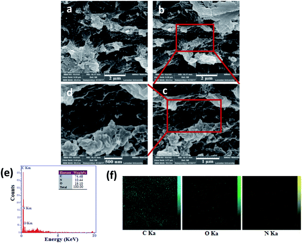
FE-SEM images were used for characterization of the structure of the GN–CS hydrogel. FE-SEM images of GN–CS aerogel are shown in Fig. 2a–d which indicated GN–CS aerogel has a well-defined and interrelated 3D porous network microstructure with pore sizes in the range of 1–2 micrometers. 3D network construction happened owing to the reaction between glutaraldehyde molecules and the amine group in chitosan and GN. This imine reaction results in cross-linking of GN nanosheets and polymer chains and finally hydrogel formation. The smaller pores with sized in the range of 80–250 nm can be seen (Fig. 2c and d). Energy dispersive X-ray spectroscopy (EDX) spectrum shows that GN–CS contains three kinds of elements C, O, and N (Fig. 2e). The elemental maps of C, O, and N in GN–CS are shown in Fig. 2f.
Swelling investigation
The swelling behaviour of GN–CS hydrogel was studied in distilled water using 1.5 g of wet GN–CS hydrogel. Fig. 3 shows pictures of hydrogel swelling in water. Using eqn (1), swelling degree of GN–CS hydrogel is calculated to be about 15![[thin space (1/6-em)]](https://www.rsc.org/images/entities/char_2009.gif) 700.5% (157 g/g) this is a high swelling value compared to previously studied adsorbents.
700.5% (157 g/g) this is a high swelling value compared to previously studied adsorbents.
 | ||
| Fig. 3 Photos of (a) wet hydrogel before immersion in water, (b) swollen gel in water and (c) dried gel. | ||
Adsorption investigation
The adsorption ability of GN–CS was evaluated using Janus green B (JB) and Congo red (CR). The time-dependent UV-Vis absorption spectra of CR and JB under the adsorption condition in the presence of GN–CS are depicted in Fig. 4a and b. The absorbance of CR at 495 nm rapidly decreased as the removal efficiency reached to 100% after 10 min. In Fig. 4b, the absorbance of JB at 603 nm decreased slightly. The maximum removal was noticed at 120 min (30%) further than which it became constant. The results show that GN–CS is a potential absorbent for anionic dyes from aqueous solution. CR was therefore selected for further adsorption study.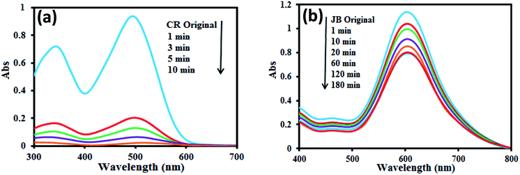 | ||
| Fig. 4 Time dependent UV-Vis spectra during adsorption of (a) CR and (b) JB, [CR or JB] = 20.0 mg L−1, adsorbent amount = 15.0 mg, pH 0 7.0. | ||
Effect of pH
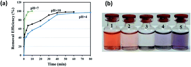
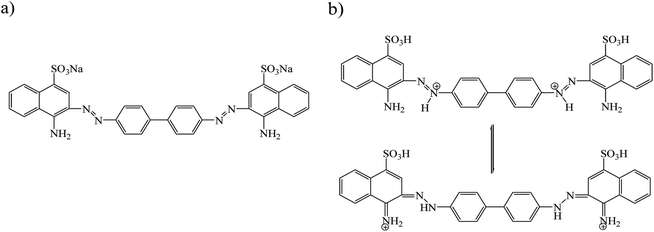
The adsorption of CR was investigated in the pH range of 4.0–10.0 (Fig. 5a and b). The original pH of CR solution was 7.0; the acidic and basic pH was adjusted by adding of small amounts of 0.1 M HCl or NaOH solution. Fig. 5a, shows that maximum adsorption occurred at pH 7.0. The removal efficiency of CR by GN–CS at pH 7.0 is 100% after 10 min, it is 56.5% and 70.4% at pH 4.0 and pH 10.0, respectively. Structure of the dye molecule at diverse pH is shown in Fig. 6. CR is an acidic dye, and in the aqueous medium it is first dissolved and converted to anionic dye at natural or basic solution while at acidic solution protonated and transformed to cationic dye. At pH < 7.0 chitosan is a cationic polymer; also the surface of aminated graphene is positive so that the surface charge of GN–CS is 36.8 mV. The adsorption of CR decreased at pH 4.0 due to the repulsion force between positive charges in protonated CR (Fig. 6b) and surface of GN–CS. At pH above 7.0, the numbers of positive charge in GN–CS decreased (11.2 mV) and the CR is as anionic form (Fig. 6a) therefore, there is an electrostatic attraction between CR molecules and GO–CS. On the other hand the excess OH ions at basic pH compete with the sulfonate groups of CR and the adsorbed dye is reduced compared to natural pH.Effect of contact time and concentration of CR
The time-dependent behavior of CR adsorption over GN–CS was achieved at room temperature. The result is shown in Fig. 7a. The adsorption rate of CR on the aerogel adsorbent was fast for the first 1 min indicating the immediate adsorption of CR and it can be attributed to large surface area and accessibility of active sites of GN–CS aerogel. Fig. 7a is displayed that the equilibrium time for CR is about 10 min under defined conditions and the percentage adsorption is reached to 100% at this time.The effect of initial concentration on the adsorption of CR is shown in Fig. 7b. The adsorption capacity raised from 10.0 to 356.0 mg g−1 as the initial CR concentration increased from 5.0 to 500.0 mg L−1. The higher initial concentration offers a higher driving force to overwhelm all mass transfer resistances of CR molecules between the aqueous phase and solid phase.47 Table 1 represents the correlation between different parameters of adsorption experiment. The maximum adsorption capacity of GN–CS was established to be 356.0 mg g−1 for 500.0 mg L−1 concentration of CR.
| CR concentration (mg L−1) | 5.0 | 10.0 | 20.0 | 30.0 | 50.0 | 100.0 | 200.0 | 300.0 | 400.0 | 500.0 |
| RE (%) | 100 | 100 | 100 | 100 | 100 | 90.6 | 63.57 | 53.2 | 44.1 | 35.6 |
| Equilibrium time (min) | 3 | 5 | 10 | 50 | 100 | 480 | 600 | 720 | 1200 | 1440 |
| qe (mg g−1) | 10.0 | 20.0 | 40.0 | 60.0 | 100.0 | 181.2 | 254.27 | 319.2 | 352.8 | 356.0 |
Adsorption kinetics
Adsorption is a physicochemical process that includes the mass transfer of a solute from the liquid phase to the adsorbent's surface.48 The adsorption kinetics of CR onto GO–CS was studied by four kinetic models including pseudo-first-order, pseudo-second-order, Elovich and intraparticle diffusion. The linear form of pseudo-first order equation49 expressed as:
ln![[thin space (1/6-em)]](https://www.rsc.org/images/entities/char_2009.gif) (qe − qt) = ln (qe − qt) = ln![[thin space (1/6-em)]](https://www.rsc.org/images/entities/char_2009.gif) qe.cal − K1t qe.cal − K1t
| (4) |
The parameters of this equation are defined in Table 2. The values of K1 and qe.cal were calculated from slope and intercept of linear curve ln(qe − qt) vs. t as presented in Fig. 8a and are presented in Table 2. The correlation coefficient R2 for the pseudo-first-order model is 0.964, and important differences exist between the calculated qe.cal (26.83 mg g−1) value and experimental qe.exp (40.0 mg g−1) value. Therefore, the adsorption of Congo red onto GN–CS does not follow the pseudo-first-order kinetic model.
| Model | parameters | Definition | Values |
|---|---|---|---|
| Pseudo-first-order | qe.exp (mg g−1) | Experimental adsorption capacity at equilibrium | 40.0 |
| qe.cal (mg g−1) | Calculated adsorption capacity | 26.83 | |
| K1 (min−1) | Rate constant | 0.735 | |
| R2 | Correlation coefficient | 0.964 | |
| Pseudo-second-order | qe.cal (mg g−1) | Calculated adsorption capacity | 41.15 |
| K2 (g mg−1 min−1) | Rate constant | 0.088 | |
| R2 | Correlation coefficient | 0.999 | |
| Elovich | α (mg g−1 min−1) | Initial adsorption rate | 95![[thin space (1/6-em)]](https://www.rsc.org/images/entities/char_2009.gif) 731 731 |
| β (g mg−1) | Related to activation energy for chemisorption | 0.310 | |
| R2 | Correlation coefficient | 0.962 | |
| Intraparticle diffusion | C1 | Intercept at stage i | 3.480 |
| Kid,1 (mg g−1 min1/2) | Rate constant | 21.638 | |
| R12 | Correlation coefficient | 0.881 | |
| C2 | Intercept at stage i | 32.881 | |
| Kid,2 (mg g−1 min1/2) | Rate constant | 2.423 | |
| R22 | Correlation coefficient | 0.793 |
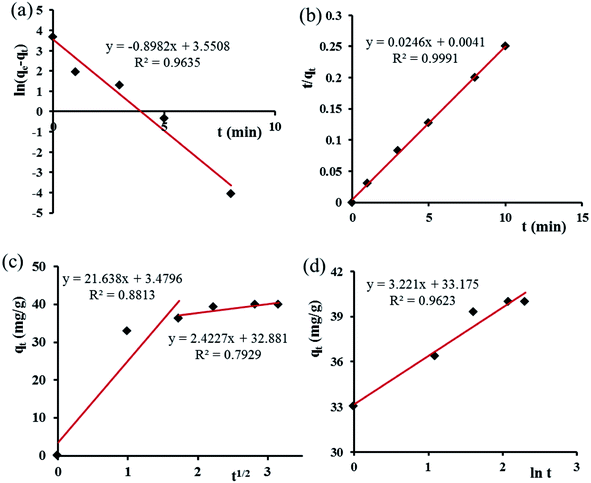 | ||
| Fig. 8 (a) Pseudo-first-order, (b) pseudo-second-order, (c) intraparticle diffusion and (d) Elovich models for adsorption of CR over GN–CS. | ||
The pseudo-second-order rate equation50 is represented as:
 | (5) |
The parameters of this equation are defined in Table 2. The values of qe.cal and K2 were calculated from slope and intercept of linear curve t/qt vs. t as presented in Fig. 8b and are presented in Table 2. For the adsorption of Congo red by GN–CS, linear relationships with a high correlation coefficient (R2 = 0.999) between t/qt and t indicated that the adsorption process could be fitted by the pseudo-second-order model. Furthermore, for the pseudo-second-order model, the calculated qe.cal (41.15 mg g−1) value agree fine with the experimental qe.exp (40.0 mg g−1) value.
The intraparticle diffusion model51 is usually to characterize the rate controlling step, and it is expressed as:
| qt = Kidt1/2 + Ci | (6) |
The parameters of this equation are defined in Table 2. The value of Ci gives the information regarding the thickness of the boundary layer. The values of kid and Ci calculated from slope and intercept of linear curve qt versus t1/2 as presented in Fig. 8c and are shown in Table 2. Fig. 8c shows that the plan did not pass over the origin that indicated the intraparticle diffusion was not the only rate-limiting step and the adsorption of CR onto GN–CS was a complex process. The initial sharp step is due to the external surface adsorption or instantaneous adsorption stage and the second portion was the gradual adsorption stage. The higher slope of the initial sharp stage showed that the rate was very rapid due to the instantaneous availability of large surface area and active adsorption sites. The lower slope of the second portion indicated a low adsorption rate because of the decreased dye concentration gradient that caused dye molecules to diffuse at long time in the micropores.
The Elovich kinetic equation52 is expressed as
 | (7) |
The parameters of this equation are defined in Table 2. The values of β and α calculated from slope and intercept of the plot of qt versus ln![[thin space (1/6-em)]](https://www.rsc.org/images/entities/char_2009.gif) t as presented in Fig. 8d. The parameters of the Elovich equation were determined and are given in Table 2. The correlation coefficient R2 is lower than the pseudo-second-order value. This result designates that Elovich model was unsuitable to represent adsorption kinetic of CR onto GN–CS, and the adsorption process was not controlled by chemisorption.
t as presented in Fig. 8d. The parameters of the Elovich equation were determined and are given in Table 2. The correlation coefficient R2 is lower than the pseudo-second-order value. This result designates that Elovich model was unsuitable to represent adsorption kinetic of CR onto GN–CS, and the adsorption process was not controlled by chemisorption.
Adsorption isotherm
Adsorption isotherm represents the distribution of adsorbate between adsorbent and solution at equilibrium. Langmuir,53 Freundlich,54 Temkin55 and Dubinin–Radushkevich (D–R),56 four most commonly models, are used to describe the adsorption mechanism more deeply.The Langmuir model uses a monolayer adsorbate on the surface of the adsorbent, and it is based on the assumption that adsorption occurs on the homogeneous surface, without interactions between the adsorbed dyes molecules. The Langmuir isotherm is given by eqn (8):
 | (8) |
The values of qmax and KL were calculated from slope and intercept of linear curve Ce/qe vs. Ce as presented in Fig. 9a. These parameters were calculated and are given in Table 3. The value of the correlation coefficient, R2, for the fit of isotherm data to Langmuir equation is more close to 1.0 than that for Freundlich, Temkin and D–R equations. Consequently, the experimental equilibrium adsorption data are well explained by the Langmuir equation compared to other models. This suggested the monolayer adsorption of CR dye over the homogeneous surface of GN–CS. The maximum adsorption capacity of GN–CS for Congo red calculated from the Langmuir equation is 384.62 mg g−1 and listed in Table 4 with literature values of qmax of other adsorbents for CR adsorption. Comparing the obtained results demonstrates a high adsorption capacity of GN–CS aerogel for Congo red.
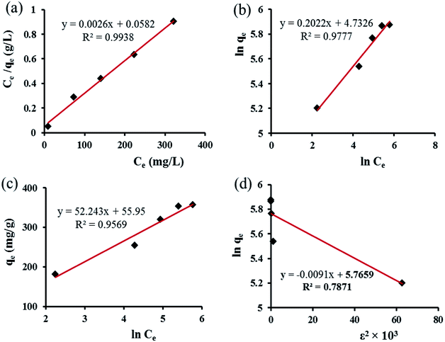 | ||
| Fig. 9 (a) Langmuir, (b) Freundlich, (c) Temkin and (d) Dubinin–Radushkevich adsorption isotherms for CR on GN–CS. | ||
| Isotherm model | Parameters | Value |
|---|---|---|
| Langmuir | qmax (mg g−1) | 384.62 |
| KL (L mg−1) | 0.0447 | |
| RL | 0.0428–0.1828 | |
| R2 | 0.9938 | |
| Freundlich | KF (L mg−1) | 113.59 |
| n | 4.9456 | |
| R2 | 0.9777 | |
| Temkin | k0 (L mg−1) | 2.9182 |
| ΔQ (J mol−1) | 47.424 | |
| R2 | 0.9569 | |
| D–R | qD (mg g−1) | 319.226 |
| KD (mol2 J−2) | 9.1 × 10⁻³ | |
| E (kJ mol−1) | 7.4125 | |
| R2 | 0.7871 |
| Type of adsorbent | qmax (mg g−1) | Reference |
|---|---|---|
| Co/G | 934.9 | 41 |
| CS/CTAB | 433.12 | 25 |
| CS/CNT | 405.4 | 26 |
| CS/TX-100 | 378.79 | 24 |
| CS/GO | 370.37 | 42 |
| CS/SDS beads | 318.47 | 24 |
| GO/CS/ETCH | 294.12 | 43 |
| CS beads | 223.25 | 25 |
| Magnetic GO | 143.60 | 33 |
| NiO/graphene | 123.89 | 34 |
| GO/Fe3O4 | 98.8 | 35 |
| Fe3O4@mTiO2@GO | 89.95 | 36 |
| CS/montmorillonite | 74.73 | 37 |
| Fe3O4@graphene | 33.66 | 38 |
| Chitosan resins | 32.11 | 39 |
| GO/polyacrylamide hydrogel | 8.0 | 40 |
| GN–CS aerogel | 384.62 | This work |
The Langmuir isotherm can be declared in terms of a dimensionless equilibrium parameter which is calculated using eqn (9).
 | (9) |
The Freundlich model assumes that adsorption occurs in the heterogeneous surface and it is expressed by eqn (10):
 | (10) |
![[thin space (1/6-em)]](https://www.rsc.org/images/entities/char_2009.gif) qe vs. ln
qe vs. ln![[thin space (1/6-em)]](https://www.rsc.org/images/entities/char_2009.gif) Ce as presented in Fig. 9b and listed in Table 3. In the Freundlich isotherm model, the value of n indicates the type of isotherm. When n is equal to 1.0, the adsorption is linear. Additional, n below unity shows that adsorption is a chemical process; while, n above unity is connected with favorable adsorption and a physical process. The values of n are larger than 1 (n = 4.946), indicating that CR is favorably adsorbed by GN–CS.
Ce as presented in Fig. 9b and listed in Table 3. In the Freundlich isotherm model, the value of n indicates the type of isotherm. When n is equal to 1.0, the adsorption is linear. Additional, n below unity shows that adsorption is a chemical process; while, n above unity is connected with favorable adsorption and a physical process. The values of n are larger than 1 (n = 4.946), indicating that CR is favorably adsorbed by GN–CS.
The Temkin isotherm model has expected that the heat of adsorption of all the dye molecules in the layer declines linearly with coverage due to adsorbate–adsorbate interactions. The linear form of Temkin isotherm model given as:
qe = B![[thin space (1/6-em)]](https://www.rsc.org/images/entities/char_2009.gif) ln ln![[thin space (1/6-em)]](https://www.rsc.org/images/entities/char_2009.gif) k0 + B k0 + B![[thin space (1/6-em)]](https://www.rsc.org/images/entities/char_2009.gif) ln ln![[thin space (1/6-em)]](https://www.rsc.org/images/entities/char_2009.gif) Ce Ce
| (11) |
![[thin space (1/6-em)]](https://www.rsc.org/images/entities/char_2009.gif) Ce as presented in Fig. 9b and listed in Table 3. The variation of adsorption energy, ΔQ= (−ΔH), is positive which suggests that the adsorption is an exothermic process.
Ce as presented in Fig. 9b and listed in Table 3. The variation of adsorption energy, ΔQ= (−ΔH), is positive which suggests that the adsorption is an exothermic process.
The D–R model is generally used to differentiate between physical and chemical adsorption and its linear form is given as:
ln![[thin space (1/6-em)]](https://www.rsc.org/images/entities/char_2009.gif) qe = ln qe = ln![[thin space (1/6-em)]](https://www.rsc.org/images/entities/char_2009.gif) qD − KDε2 qD − KDε2
| (12) |
 | (13) |
The values of qD and KD can be computed from the slope and intercept of the plot of ln![[thin space (1/6-em)]](https://www.rsc.org/images/entities/char_2009.gif) qe against ε2. The constant KD gives valuable information about the mean free energy E (kJ mol−1) of adsorption per molecule of adsorbate and it can be calculated using the following relationship:
qe against ε2. The constant KD gives valuable information about the mean free energy E (kJ mol−1) of adsorption per molecule of adsorbate and it can be calculated using the following relationship:
 | (14) |
The value of E is valuable for appraising the type of adsorption process. When E < 8.0 kJ mol−1, the adsorption type can be described by physical adsorption.56 In this study, the value of E was 7.41 kJ mol−1, suggested that adsorption process of CR onto adsorbent is a physical-sorption process.
Reusability study
In reusability study, 0.015 g of GN–CS was used for adsorption of 20.0 mg L−1 CR solution (30.0 mL). Remarkably GN–CS absolutely removes 20.0 mg L−1 of CR at first cycle. CR molecules were desorbed completely from adsorbents after repeated washing with 4![[thin space (1/6-em)]](https://www.rsc.org/images/entities/char_2009.gif) :
:![[thin space (1/6-em)]](https://www.rsc.org/images/entities/char_2009.gif) 1 solution of EtOH
1 solution of EtOH![[thin space (1/6-em)]](https://www.rsc.org/images/entities/char_2009.gif) :
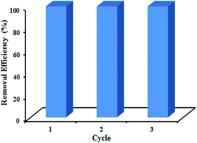
:![[thin space (1/6-em)]](https://www.rsc.org/images/entities/char_2009.gif) DMF three times. Then, the adsorbent was dried at 70 °C before reused for the next adsorption. The results are displayed in Fig. 10 that shows the efficiency of dye removal was 100% after three cycles, so the as-prepared adsorbent is reusable.
DMF three times. Then, the adsorbent was dried at 70 °C before reused for the next adsorption. The results are displayed in Fig. 10 that shows the efficiency of dye removal was 100% after three cycles, so the as-prepared adsorbent is reusable.
Removal of CR dye with GN and GO
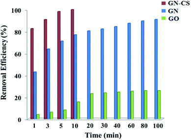
To further demonstrate the role of graphene nanosheets and surface charge in adsorption, GN and GO were individually tested for removing the CR dye. For this purpose, 0.015 g of GN or GO was used for adsorption of 20.0 mg L−1 CR dye solution (30.0 mL) at pH 7.0. The removal efficiency of GN–CS, GN, and GO over time is displayed in Fig. 11. The results indicated that the nanosheets of GN have a significant potential for color adsorption but at a much lower rate than GN–CS. While the removal efficiency of GN–CS reaches to 100% in 10 minutes, this value is 91% and 26% over 100 min for GN and GO, respectively. The result indicates that GO is not suitable adsorbent for CR dye that it can be attributed to repulsion interactions between negative charges of CR dye molecules and GO.Conclusion
The nanocomposite hydrogel was prepared by using low-toxic and cost-effective precursors in mild condition under 60 second time. GN sheets and CS chains are crosslinked by glutaraldehyde, forming a 3D network. The GN–CS aerogel that obtained by freeze-drying of the hydrogel were used to remove organic dyes. The equilibrium studies reveal a pseudo-second-order kinetic model and Langmuir isotherm model was best fitted. The maximum dye adsorption capacity calculated from the Langmuir isotherm equation was 384.62 mg g−1. Moreover, the aerogel was stable and easily recovered. Simple and rapid synthesis, high absorbance capacity, absorption kinetics and recyclability of the GN–CS aerogel indicate good potential for industrial applications.Conflicts of interest
There are no conflicts of interest.Acknowledgements
The authors are grateful to the Lorestan University for financial support of this work.References
- M. Vakili, M. Rafatullah, B. Salamatinia, A. Z. Abdullah, M. H. Ibrahim, K. B. Tan, Z. Gholami and P. Amouzgar, Carbohydr. Polym., 2014, 113, 115–130 CrossRef CAS PubMed.
- A. Gottlieb, C. Shaw, A. Smith, A. Wheatley and S. Forsythe, J. Biotechnol., 2003, 101, 49–56 CrossRef CAS PubMed.
- P. Frid, S. V. Anisimov and N. Popovic, Brain Res. Rev., 2007, 53, 135–160 CrossRef CAS PubMed.
- E. Y. Ozmen and M. Yilmaz, J. Hazard. Mater., 2007, 148, 303–310 CrossRef CAS PubMed.
- G. Mezohegyi, F. P. van der Zee, J. Font, A. Fortuny and A. Fabregat, J. Environ. Manage., 2012, 102, 148–164 CrossRef CAS PubMed.
- S. Wang, C. W. Ng, W. Wang, Q. Li and Z. Hao, Chem. Eng. J., 2012, 197, 34–40 CrossRef CAS.
- H. W. Liang, X. Cao, W. J. Zhang, H. T. Lin, F. Zhou, L. F. Chen and S. H. Yu, Adv. Funct. Mater., 2011, 21, 3851–3858 CrossRef CAS.
- A. K. Geim and K. S. Novoselov, Nat. Mater., 2007, 6, 183–191 CrossRef CAS PubMed.
- C. N. R. Rao, A. K. Sood, K. S. Subrahmanyam and A. Govindaraj, Angew. Chem., Int. Ed., 2009, 48, 7752–7777 CrossRef CAS PubMed.
- T.-T. Tang, Y. Zhang, C.-H. Park, B. Geng, C. Girit, Z. Hao, M. C. Martin, A. Zettl, M. F. Crommie and S. G. Louie, Nat. Nanotechnol., 2010, 5, 32–36 CrossRef CAS PubMed.
- R. K. Paul, M. Ghazinejad, M. Penchev, J. Lin, M. Ozkan and C. S. Ozkan, Small, 2010, 6, 2309–2313 CrossRef CAS PubMed.
- Z. Liu, J. T. Robinson, X. Sun and H. Dai, J. Am. Chem. Soc., 2008, 130, 10876–10877 CrossRef CAS PubMed.
- O. Akhavan and E. Ghaderi, ACS Nano, 2010, 4, 5731–5736 CrossRef CAS PubMed.
- S. Omidi, A. Kakanejadifard and F. Azarbani, J. Mol. Liq., 2017, 242, 812–821 CrossRef CAS.
- M. D. Stoller, S. Park, Y. Zhu, J. An and R. S. Ruoff, Nano Lett., 2008, 8, 3498–3502 CrossRef CAS PubMed.
- S. Park, K.-S. Lee, G. Bozoklu, W. Cai, S. T. Nguyen and R. S. Ruoff, ACS Nano, 2008, 2, 572–578 CrossRef CAS PubMed.
- Y. Xu, Q. Wu, Y. Sun, H. Bai and G. Shi, ACS Nano, 2010, 4, 7358–7362 CrossRef CAS PubMed.
- W. Zhang, C. Zhou, W. Zhou, A. Lei, Q. Zhang, Q. Wan and B. Zou, Bull. Environ. Contam. Toxicol., 2011, 87, 86 CrossRef CAS PubMed.
- Y. Chang, S.-T. Yang, J.-H. Liu, E. Dong, Y. Wang, A. Cao, Y. Liu and H. Wang, Toxicol. Lett., 2011, 200, 201–210 CrossRef CAS PubMed.
- V. C. Sanchez, A. Jachak, R. H. Hurt and A. B. Kane, Chem. Res. Toxicol., 2011, 25, 15–34 CrossRef PubMed.
- H. Sereshti, S. Samadi, S. Asgari and M. Karimi, RSC Adv., 2015, 5, 9396–9404 RSC.
- Z. Dong, D. Wang, X. Liu, X. Pei, L. Chen and J. Jin, J. Mater. Chem. A, 2014, 2, 5034–5040 CAS.
- J. Liu, K. Zhu, T. Jiao, R. Xing, W. Hong, L. Zhang, Q. Zhang and Q. Peng, Colloids Surf., A, 2017, 529, 668–676 CrossRef CAS.
- S. Chatterjee, D. S. Lee, M. W. Lee and S. H. Woo, Bioresour. Technol., 2009, 100, 3862–3868 CrossRef CAS PubMed.
- S. Chatterjee, D. S. Lee, M. W. Lee and S. H. Woo, Bioresour. Technol., 2009, 100, 2803–2809 CrossRef CAS PubMed.
- S. Chatterjee, M. W. Lee and S. H. Woo, Bioresour. Technol., 2010, 101, 1800–1806 CrossRef CAS PubMed.
- Y. Chen, L. Chen, H. Bai and L. Li, J. Mater. Chem. A, 2013, 1, 1992–2001 CAS.
- L. Gan, S. Shang, E. Hu, C. W. M. Yuen and S.-x. Jiang, Appl. Surf. Sci., 2015, 357, 866–872 CrossRef CAS.
- J. Deng, B. Lei, A. He, X. Zhang, L. Ma, S. Li and C. Zhao, J. Hazard. Mater., 2013, 263, 467–478 CrossRef PubMed.
- L. Wang, J. Li, C. Mao, L. Zhang, L. Zhao and Q. Jiang, Dalton Trans., 2013, 42, 8070–8077 RSC.
- M. A. Kamal, S. Bibi, S. W. Bokhari, A. H. Siddique and T. Yasin, React. Funct. Polym., 2017, 110, 21–29 CrossRef CAS.
- Q. Du, J. Sun, Y. Li, X. Yang, X. Wang, Z. Wang and L. Xia, Chem. Eng. J., 2014, 245, 99–106 CrossRef CAS.
- X.-r. Zhang, J.-l. Gong, G.-m. Zeng and J.-h. Deng, China Environ. Sci., 2013, 33, 1379–1385 CAS.
- X. Rong, F. Qiu, J. Qin, H. Zhao, J. Yan and D. Yang, J. Ind. Eng. Chem., 2015, 26, 354–363 CrossRef CAS.
- M. Namvari and H. Namazi, Int. J. Environ. Sci. Technol., 2014, 11, 1527–1536 CrossRef CAS.
- L. Li, X. Li, H. Duan, X. Wang and C. Luo, Dalton Trans., 2014, 43, 8431–8438 RSC.
- L. Wang and A. Wang, J. Hazard. Mater., 2007, 147, 979–985 CrossRef CAS PubMed.
- Y. Yao, S. Miao, S. Liu, L. P. Ma, H. Sun and S. Wang, Chem. Eng. J., 2012, 184, 326–332 CrossRef CAS.
- L.-X. Zeng, Y.-F. Chen, Q.-Y. Zhang, Y. Kang and J.-W. Luo, Desalin. Water Treat., 2014, 52, 7733–7742 CrossRef CAS.
- W. Cui, J. Ji, Y.-F. Cai, H. Li and R. Ran, J. Mater. Chem. A, 2015, 3, 17445–17458 CAS.
- S. Wang, X. Li, Y. Liu, C. Zhang, X. Tan, G. Zeng, B. Song and L. Jiang, J. Hazard. Mater., 2018, 342, 177–191 CrossRef CAS PubMed.
- B. Y. Z. Hiew, L. Y. Lee, X. J. Lee, S. Thangalazhy-Gopakumar, S. Gan, S. S. Lim, G.-T. Pan, T. C.-K. Yang, W. S. Chiu and P. S. Khiew, Process Saf. Environ. Prot., 2018, 116, 262–286 CrossRef CAS.
- D. C. Marcano, D. V. Kosynkin, J. M. Berlin, A. Sinitskii, Z. Sun, A. Slesarev, L. B. Alemany, W. Lu and J. M. Tour, ACS Nano, 2010, 4, 4806–4814 Search PubMed.
- B. Xue, J. Zhu, N. Liu and Y. Li, Catal. Commun., 2015, 64, 105–109 CrossRef CAS.
- N. H. Kim, T. Kuila and J. H. Lee, J. Mater. Chem. A, 2013, 1, 1349–1358 CAS.
- R. J. Samuels, J. Polym. Sci., Part B: Polym. Phys., 1981, 19, 1081–1105 CrossRef CAS.
- G. A. Sayğılı, J. Mol. Liq., 2015, 211, 515–526 CrossRef.
- H. Zhu, R. Jiang, L. Xiao and G. Zeng, Bioresour. Technol., 2010, 101, 5063–5069 CrossRef CAS PubMed.
- K. Santhy and P. Selvapathy, Bioresour. Technol., 2006, 97, 1329–1336 CrossRef CAS PubMed.
- Y.-S. Ho and G. McKay, Process Biochem., 1999, 34, 451–465 CrossRef CAS.
- A. Kausar, H. N. Bhatti and G. MacKinnon, Colloids Surf., B, 2013, 111, 124–133 CrossRef CAS PubMed.
- N. A. Oladoja and A. L. Ahmad, Sep. Purif. Technol., 2013, 116, 230–239 CrossRef CAS.
- I. Langmuir, J. Am. Chem. Soc., 1918, 40, 1361–1403 CrossRef CAS.
- H. Freundlich, Z. Phys. Chem., 1907, 57, 385–470 CAS.
- S. J. Allen, Q. Gan, R. Matthews and P. A. Johnson, Bioresour. Technol., 2003, 88, 143–152 CrossRef CAS PubMed.
- C. Abasi, A. Abia and J. Igwe, Environ. Res. J., 2011, 5, 104–113 CrossRef.
Footnote |
| † Electronic supplementary information (ESI) available. See DOI: 10.1039/c8ra00510a |
| This journal is © The Royal Society of Chemistry 2018 |

