 Open Access Article
Creative Commons Attribution 3.0 Unported Licence
In situ synthesis of MoS2/graphene nanosheets as free-standing and flexible electrode paper for high-efficiency hydrogen evolution reaction†
Xianghui Zhang *a,
Mingguang Zhanga,
Yiqun Tiana,
Jing Youa,
Congxing Yangb,
Jun Sub,
Yuebin Lia,
Yihua Gao
 b and
Haoshuang Gu*a
aHubei Collaborative Innovation Center for Advanced Organic Chemical Materials, Hubei Key Laboratory of Ferro & Piezoelectric Materials and Devices, Faculty of Physics & Electronic Sciences, Hubei University, Wuhan, 430062, P. R. China. E-mail: xhzhang@hubu.edu.cn; guhsh@hubu.edu.cn
bCenter for Nanoscale Characterization and Devices, School of Physics, Wuhan National Laboratory for Optoelectronics, Huazhong University of Science and Technology, Luoyu Road 1037, Wuhan 430074, P. R. China
First published on 16th March 2018
Abstract
In this article, an exquisite flexible hybrid MoS2/graphene free-standing electrocatalyst paper was fabricated by a one-step in situ solvothermal process. The assembled MoS2/graphene catalysts exhibit significantly enhanced electrocatalytic activity and cycling stability towards the splitting of water in acidic solution. Furthermore, a strategic balance of abundant active sites at the edge of the S–Mo–S layers with efficient electron transfer in the MoS2/graphene hybrid catalyst plays a key role in controlling the electrochemical performance of the MoS2 nanosheets. Most importantly, the hybrid MoS2/graphene nanosheet paper shows excellent flexibility and high electrocatalytic performance under the various bending states. This work demonstrates an opportunity for the development of flexible electrocatalysts, which have potential applications in renewable energy conversion and energy storage systems.
Introduction
To address the issues of the global energy crisis and environmental contamination, researchers have devoted considerable attention to hydrogen (H2) as a renewable and environmentally-friendly energy source to replace the current hydrocarbon fuels. One possible route to target is to utilize solar energy directly or indirectly (through wind power, for instance) to split water to produce H2.1 Presently, producing H2 from the electrocatalytic splitting of water using the hydrogen evolution reaction (HER) holds tremendous promise because of the high energy efficiency and the economical and practical advantages.2 An advanced catalyst for the HER should play an important role in reducing the overpotential and consequently increasing the efficiency of this electrochemical process. Although the most effective HER electrocatalysts are Pt or Pt-based materials, their high cost and low abundance substantially restrict their large-scale application. Thus, it remains challenging to develop highly active HER catalysts based on non-noble-metal materials that are more abundant and lower cost.3–8Molybdenum disulfide (MoS2) is a layered transition metal dichalcogenide (TMD), which has triggered broad attention as a typical two-dimensional (2D) semiconductor nanomaterial. The structure of MoS2 is based on a hexagonal crystal, where each Mo atom is six-fold coordinated, hexagonally packed between two three-fold coordinated sulfur atoms. Each S–Mo–S layer is weakly bonded to other S–Mo–S layers by van der Waals forces. Recent works showed MoS2 to be a promising electrocatalyst for the HER.9–15 It has been suggested that the electrocatalyst activation originates from the unsaturated sulfur atoms at the edges of the MoS2 plates, while the basal planes were often thought to be catalytically inert with some exceptions. As a result, nanosized MoS2 with a high degree of exposed edges should be more active for HER electrocatalysis than materials in bulk forms.16–18 Enormous effort has been dedicated to exposing more edge sites to enhance MoS2 HER activity by engineering various morphologies, such as nanoparticles,19 nanoplates,20 nanosheets,21,22 nanoflowers,23 nanoboxes,24,25 nanoporous films26 and heterolayer nanowires.27 The electrical conductivity of catalysts is another crucial factor affecting the electrocatalytic activity because high conductivity ensures fast electron transport during the catalytic process. However, poor electrical conductivity often exists both in dispersed nanostructure MoS2 catalysts and between the S–Mo–S layers of MoS2, restricting the activity.28 Considerable attention has been focused on accelerating electron transfer by coupling MoS2 with conductive substrates, such as nanoporous gold,29,30 3D Ni foam,31 metal oxides,32–34 activated carbon,35 carbon fibers,36,37 and carbon nanotubes (CNTs).38,39 Among these conductive supports, graphene, particularly reduced graphene oxide (RGO), has attracted much attention because of its excellent electron transport properties, chemical stability and solution-phase processing compatibility.40,41 Therefore, graphene supported MoS2 nanostructures appear to be highly active and stable electrocatalysts. However, all of the MoS2/graphene hybrid nanostructure catalysts mentioned above were prepared in powdered form. Thus they had to be dropped onto the surface of a conductive substrate (e.g. a glassy carbon electrode) and then be immobilized by binding Nafion or PTFE (polytetrafluoroethylene) polymer as a working electrode. As a result, the binding polymer might block some catalytically active sites, increase the series resistance, and thus decrease the overall activity of the material. For this reason, binder-free HER catalysts based on graphene with high electrocatalytic performance are highly interesting. On the other hand, an appropriate loading rate of MoS2 onto the graphene nanosheet is one of the significant parameters to study in MoS2/graphene hybrid electrocatalysts to balance abundant active sites at the edge of S–Mo–S layers with efficient electron transfer. However, so far there have been almost no reports on the activity of MoS2/graphene hybrid electrocatalysts sensitive to the MoS2 nanostructure loading rate.
Herein, we synthesize MoS2/graphene hybrid nanosheets by a one-step in situ solvothermal method and fabricate a free-standing electrocatalyst paper for the HER to address the above mentioned problems. The MoS2/graphene paper exhibits excellent flexibility, high conductivity, a large surface area and high electrocatalytic activity and durability for HER applications. What is more, we demonstrate that the loading rate of MoS2 nanosheets on graphene has an influence on the HER activity and that the catalytic activity is almost completely unaffected by the various bending states, indicating promising prospects for flexible HER devices.
Experimental
Materials synthesis
Characterization
The morphology of the as-obtained products was observed using field emission scanning microscopy (FESEM, JSM-7100F, JEOL). X-ray diffraction (XRD) was carried out from 2θ = 10° to 80° using a Bruker Advanced D8 diffractometer under Cu Kα radiation (λ = 0.1542 nm), with a voltage of 40 kV and a current of 40 mA. The phase structures were characterized using Raman spectroscopy (Jobin-Yvon HR800), with the excitation source an argon-ion laser (λ = 515 nm). Transmission electron microscopy (TEM) and high resolution transmission electron microscopy (HRTEM) images were obtained under an acceleration voltage of 200 kV with a FEI Tecnai G20 TEM instrument. The high resolution energy dispersive X-ray spectroscopy (EDS) mapping measurements were carried out with a probe-Cs-corrected HRTEM instrument (FEI Titan G2 60-300) in scanning TEM mode (STEM). The chemical composition and bonding states were investigated by X-ray photoelectron spectroscopy (XPS, Escalab 250Xi) using an Al Kα source 1486.6 eV anode. All XPS spectra were corrected using the C 1s line at 284.6 eV.Electrochemical measurements
All electrochemical experiments were performed in a standard three electrode setup in 0.5 M H2SO4 at room temperature using an electrochemical workstation (ZENNIUM, ZAHENR). The prepared MoS2/graphene freestanding paper was measured as a working electrode. A commercial 20% Pt–C catalyst was used as a reference sample. An Ag/AgCl electrode with saturated KCl solution and a Pt wire were used as the reference electrode and counter electrode, respectively. The potential values reported in this study are versus the reversible hydrogen electrode (RHE). The HER activities of the samples were evaluated using linear sweep voltammetry at 10 mV s−1. Continuous cyclic voltammetry (CV) was conducted at 50 mV s−1 between 0.1 and −0.5 V to investigate the cycling stability. EIS was carried out from 105 to 0.1 Hz with an amplitude of 10 mV at the open-circuit voltage.Results and discussion
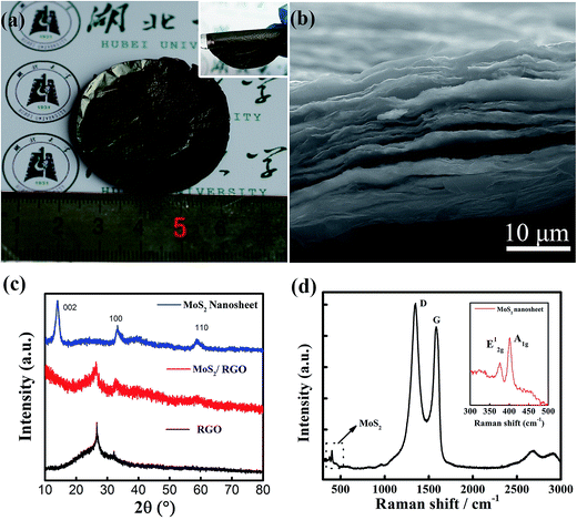
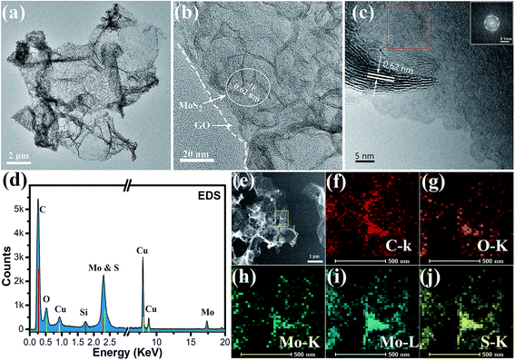
We employed a one step solvothermal reaction method to synthesize the MoS2/graphene nanocomposites and prepare the free-standing MoS2/graphene electrode paper using a vacuum filtration method, which was a facile and time-saving method. Fig. 1a is a typical photograph of the prepared MoS2/graphene freestanding paper after peeling off the membrane, with a size of 2 inches. The hybrid film appeared uniform and was a dark gray color. These freestanding papers can be randomly wrapped around a glass rod with no noticeable damage, indicating their remarkably flexible and durable properties (inset in Fig. 1a). Fig. 1b presents the cross-sectional SEM image. The MoS2/graphene layers stack together to form a compact layered structure with a thickness of about 20 μm due to van der Waals forces. The MoS2/graphene hybrid was characterized by XRD as shown in Fig. 1c. For comparison, pure RGO films and MoS2 nanosheet samples were evaluated too. The RGO films show a broad peak at 26.1°, which indicated the stacking structure of the RGO sheet. The pure MoS2 nanosheet as prepared by the same method shows three broad diffraction peaks indicating nanosize MoS2 crystal domains with a hexagonal structure (JCPDS: 65-0160). The hybrid MoS2/RGO films show two diffraction peaks relating to RGO and MoS2 (100), respectively. The absence of a (002) low-angle diffraction peak indicates that the atomic arrangement of MoS2 in the hybrid with graphene sheets was different from that in the powder form. Raman spectroscopy, as shown in Fig. 1d, revealed the characteristic D and G bands of graphene, and the peaks of MoS2 at 378 and 402 cm−1, corresponding to the E2g1 and A1g modes as shown in the inset, respectively. The lower intensity of E2g1 (in-plane Mo–S phonon mode) compared to that of A1g (out-of plane Mo–S phonon mode) indicates that the MoS2 crystals tended to show the basal-edge-rich feature of the ultrathin plate growth, in good agreement with the absence of a (002) peak in the XRD measurements.The morphology, microstructure and chemical element information for the ultra thin plate MoS2/graphene nanosheets were further obtained by TEM. As shown in Fig. 2a, the low resolution TEM image verifies that the ultrathin MoS2 nanosheets are homogeneously dispersed on the graphene sheets, indicating that the graphene sheets could be used as an efficient substrate for the nucleation and growth of MoS2 nanosheets. On the other hand, the graphene sheets show good ability to prevent the aggregation of MoS2 nanosheets, serving to enlarge the active area of HER. Furthermore, plate-like ultrathin MoS2 can be further verified by HRTEM, where each sheet contains several S–Mo–S layers with an interlayer spacing of 0.62 nm, as shown in Fig. 2b. Dense interconnected ripples and corrugations can also be observed, suggesting the basal-edge-rich feature of the ultrathin MoS2 nanosheet, in agreement with the results of XRD and Raman characterization. Furthermore, two different aligned (horizontally aligned and vertically aligned) MoS2 nanosheets were found on the GO sheet under higher resolution TEM investigations, as shown in Fig. 2c. The HRTEM image and a selected area (red square) electron diffraction pattern (inset) of horizontally aligned (basal plane exposed) MoS2 show that a few layers of MoS2 were stacked with hexagonal lattice symmetry. Part of the MoS2 layer is fully vertically aligned, resulting in dominantly exposed molybdenum or sulfur atoms, which is beneficial for higher chemical catalytic activity for the MoS2 sheets. The HRTEM image indicates the vertically aligned MoS2 composed of a several-layer structure and a lattice fringe spacing of 0.62 nm. The chemical composition of the hybrid nanosheet was further determined by an energy dispersive X-ray spectroscopy (EDS) curve and mapping using a probe-Cs-corrected TEM instrument. Fig. 2d shows the EDX spectrum of the MoS2/GO hybrid films. The results show that there were six kinds of element (Cu, Si, C, O, Mo and S) detected, of which C and O peaks come from GO, Mo and S come from MoS2, and Cu and Si come from the TEM grid and silicon escape peak. Fig. 2e–j show the STEM and STEM-EDS mapping images of C, O, Mo and S elements. It is obvious that all of the Mo, S and C elements uniformly distribute on the whole nanosheet surface. This further verified the formation of the as-predicted MoS2/graphene nanosheet hybrid structure. The signal for O comes from the incomplete reduction of graphene oxide after the solvothermal reaction. To obtain highly conductive graphene sheets, the freestanding MoS2/graphene paper was further treated by annealing at 700 °C for 2 h in Ar flow.
X-ray photoelectron spectroscopy (XPS) analyses of the annealed MoS2/graphene catalyst films were carried out to elucidate the chemical bonding structures. A typical XPS survey scanning in the binding energy range from 0 to 1200 eV is shown in Fig. 3a. For the MoS2/graphene hybrid film, Mo, S, O and C elements were detected. Meanwhile, the S 2p region (Fig. 3b) exhibits primarily a single doublet with the S 2p3/2 peak at 161.7 eV and the S 2p1/2 peak at 163.1 eV, which is consistent with the −2 oxidation state of sulfur. As shown in Fig. 3c, two characteristic peaks arising from Mo 3d5/2 and Mo 3d3/2 orbitals are located at 229 and 231.1 eV, suggesting the dominance of Mo4+ in the nanosheet. In addition, a lower peak located at 236 eV was also detected, which was attributed to Mo–O bonding at the surface of the RGO nanosheet. The oxidation degrees of the RGO sheets could be evaluated using the area ratios of the C 1s XPS peaks of oxidized (ACO) and intact (ACC) carbon atoms, as shown in Fig. 3d. The C 1s peaks were deconvoluted into two peaks that correspond to the sp2 carbon (C![[double bond, length as m-dash]](https://www.rsc.org/images/entities/char_e001.gif) C, 284.3 eV) and epoxy/hydroxyls (C–O, 285.4 eV), respectively. The ratio ACO/ACC of annealed MoS2/graphene is about 0.25, which is much lower than that of the GO nanosheet published elsewhere,43 indicating that the GO sheet has been reduced to RGO efficiently by annealing.
C, 284.3 eV) and epoxy/hydroxyls (C–O, 285.4 eV), respectively. The ratio ACO/ACC of annealed MoS2/graphene is about 0.25, which is much lower than that of the GO nanosheet published elsewhere,43 indicating that the GO sheet has been reduced to RGO efficiently by annealing.
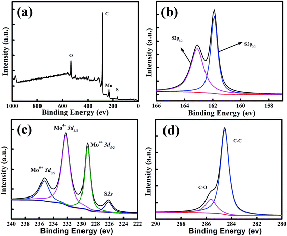 | ||
| Fig. 3 Composition characterization of the MoS2/graphene films. (a) XPS survey scan, and high-resolution scans of (b) S 2p, (c) Mo 3d and (d) C 1s electrons of the MoS2/graphene hybrid. | ||
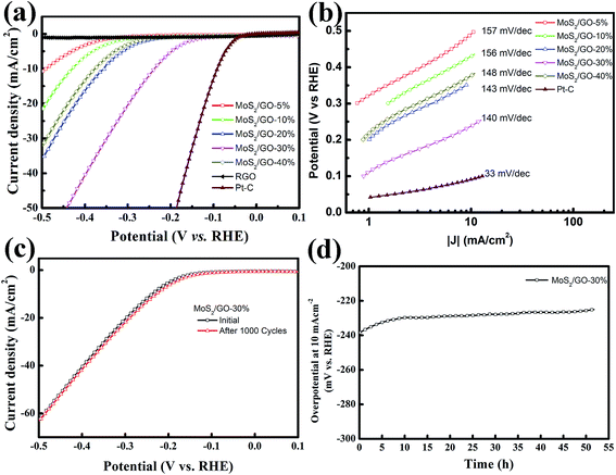
As proven by computational and experimental studies, the chemically active undercoordinated atoms at the edge sites of MoS2 play a key role in improving the HER activity.29,44 Therefore, efficient HER activity can be expected for the higher loading rate of MoS2 in the hybrid films, which introduced more edge sites. We investigated the HER activities of our MoS2/graphene hybrid thin films with different loading rates. The electrocatalytic HER performance of freestanding MoS2/graphene paper was measured in 0.5 M H2SO4 solution using linear sweep voltammetry (LSV) in a three-electrode system. The polarization curve was recorded within a cathodic potential window in the range 0.1 to −0.5 V at a 10 mV s−1 scan rate. For comparison, pure RGO film and commercial Pt–C were also assessed. Fig. 4a shows the corresponding polarization curves for the MoS2/graphene hybrid films loaded with various MoS2 nanosheet percentages from 5 to 40%. All the polarization curves have no IR compensation. As expected, the commercial Pt–C catalyst displayed the highest electrocatalytic activity, with an onset overpotential (defined here as the overpotential at which the HER current density is 1.0 mA cm−2) of 23.9 mV. In sharp contrast, the pure RGO film without MoS2 nanosheets exhibited the lowest electrocatalytic activity. The onset overpotential gradually decreased from 263.7 mV to 94.2 mV when the MoS2 nanosheet content percentage increased from 5% to 30%. However, in contrast the overpotential increased to 221.6 mV when the MoS2 nanosheet percentage was 40%. Generally, the overpotential value for a HER current density of 10 mA cm−2 is an important reference because significant hydrogen evolution can be observed and the solar-light-coupled HER apparatuses usually operate at 10–20 mA cm−2 under standard conditions (1 sun, AM 1.5).45 According to a previous report, monolayer MoS2 loaded on a 3D nanoporous gold substrate shows a low operating voltage of 226 mV as a typical overpotential for a few-layer MoS2 nanosheet.29 To achieve this current density in this work, the 5 wt%-MoS2/GO catalyst requires an overpotential of 490.2 mV. Moreover, the overpotential shows an obvious decrease from 430.3 mV to 238.5 mV when the weight percentage content of MoS2 nanosheets increases from 10% to 30%, which indicates that the MoS2 nanosheets have significantly accelerated the HER process. However, the overpotential was remarkably increased from the lowest value 238.5 mV to 377.2 mV, as the MoS2 loading rate increases from 30% to 40% in the MoS2/GO hybrid thin films, which indicated that the HER activity was suppressed in the catalyst in spite of the higher loading rate bringing more active sites. We speculate that the surface loading rate of the RGO film was the major reason for the HER activity performance degradation. Part of the MoS2 nanosheets were interstitial in the RGO hybrid thin films when the concentration of the MoS2 precursor was higher than the loading capacity of the GO sheets. This may lead to inefficient electron transfer because of the semiconducting properties of the S–Mo–S layers. For comparison, I–V curve measurements of the thin hybrid film with various loading rates were carried out to elucidate their electrical resistivity (ESI Fig. S2†). These data verified that the excellent catalytic activity of the thin MoS2/GO hybrid films may arise from the synergetic effect of the abundant active edge sites and efficient electron transfer. To obtain further insight into the HER properties of the various catalysts, the Tafel slopes were investigated. The linear portions of the Tafel plots were fit to the Tafel equation, yielding Tafel slopes of 156.7, 156.1, 142.6, 140.1 and 147.8 mV dec−1 for 5%, 10%, 20%, 30% and 40% MoS2 loading rate on RGO thin films, as shown in Fig. 4b, respectively. These results are in agreement with overpotential investigations (ESI Table 1†). Electrochemical impedance spectroscopy was performed under HER conditions. The Nyquist plots are shown in ESI Fig. S3† and reveal the charge transfer resistance for MoS2 and RGO hybrid nanosheets.
The stability of the MoS2/graphene nanosheets catalyst was evaluated by cycling the electrode at 50 mV s−1 between 0.1 and −0.5 V in 0.5 M H2SO4 solution at room temperature. The performance of the MoS2/GO-30% catalyst after 1000 cycles is shown in Fig. 4c. As observed, the polarization curve for the MoS2/GO hybrid nanosheet catalyst remained almost the same after 1000 cycles. In addition, the durability of the MoS2/GO-30% catalyst was also examined by electrolysis at a static polarization current of 10 mA cm−2 for over 50 hours, as shown in Fig. 4d. The overpotential at a current density of 10 mA cm−2 decreased by a relatively small value (from 238 to 225 mV) after 50 hours of durability determination, indicating that MoS2/graphene nanosheet catalysts are stable electrocatalysts in acidic solution.
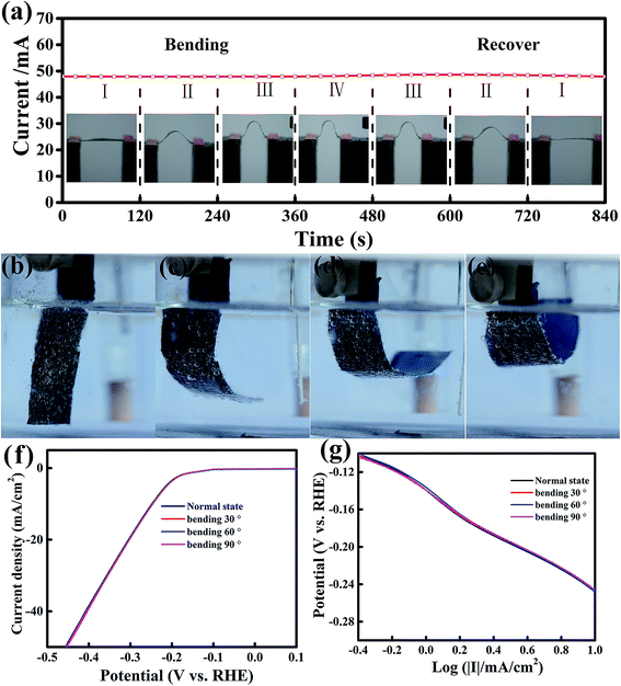
Recently, flexible and wearable electronic devices and energy storage and conversion systems, such as flexible displays, supercapacitors and solar cells, have attracted great attention.46 Therefore, it is highly interesting and urgent to investigate flexible electrocatalysts to develop a flexible power source with remarkable electrochemical performance for integration into flexible electronics.47 To develop flexible electrocatalysts, the catalytic performance should remain unchanged under various bending states. The current stability of MoS2/RGO hybrid films under four various bending curvatures was monitored at a fixed voltage of 1 V (Fig. 5a), and each bending curvature was maintained for 120 s. We found that the current was very stable and had no apparent change under various bending and recovering states, indicating that the conductance of the MoS2/RGO catalyst was hardly affected by bending stress. Furthermore, the effect of the flexibility of MoS2/RGO on catalytic activity was investigated at four various bending states, as shown in Fig. 5b–e, which were measured in 0.5 M H2SO4 acidic solution at 10 mV s−1. It is clear to see from Fig. 5f that the polarization curve almost stays the same under the various bending states. In addition, the derivative polarization curves under four various bending states are shown in Fig. 5g, which also shows that the derivative polarization curve fits a linear regression under various bending states. Therefore, the above results indicate that MoS2/RGO is an excellent flexible electrocatalyst and its electrocatalytic activity is almost unaffected by the various bending states.
Conclusion
In conclusion, we have demonstrated a one-step in situ solvothermal process for the fabrication of improved flexible hybrid MoS2/graphene free-standing electrocatalyst paper for HER applications. The MoS2/graphene catalysts exhibit significantly enhanced electrocatalytic activity and cycling stability towards the splitting of water in acidic solution, indicating the promising potential of solar energy. Furthermore, a strategic balance of abundant active edge sites with efficient electron transfer in the MoS2/graphene hybrid catalyst plays a key role in controlling the electrochemical performance of the MoS2 nanosheets. Most importantly, because of invariant performance under various bending states, the MoS2/graphene hybrid films provide a fundamental opportunity for the development of flexible electrocatalysts, which have potential technological applications in renewable energy conversion and energy storage systems.Conflicts of interest
There are no conflicts to declare.Acknowledgements
This work was financially supported by the National Natural Science Foundation of China (Grant No. 11504098 and 11474088).Notes and references
- C. Jiang, S. J. A. Moniz, A. Wang, T. Zhang and J. Tang, Chem. Soc. Rev., 2017, 46, 4645–4660 RSC.
- P. V. Kamat and J. Bisquert, J. Phys. Chem. C, 2013, 117, 14873–14875 CAS.
- X. Zhang, X. Lu, Y. Shen, J. Han, L. Yuan, L. Gong, Z. Xu, X. Bai, M. Wei, Y. Tong, Y. Gao, J. Chen, J. Zhou and Z. L. Wang, Chem. Commun., 2011, 47, 5804–5806 RSC.
- J. Li and G. Zheng, Adv. Sci., 2017, 4, 1600380 CrossRef PubMed.
- D. V. Esposito, S. T. Hunt, A. L. Stottlemyer, K. D. Dobson, B. E. McCandless, R. W. Birkmire and J. G. Chen, Angew. Chem., Int. Ed. Engl., 2010, 49, 9859–9862 CrossRef CAS PubMed.
- B. Cao, G. M. Veith, J. C. Neuefeind, R. R. Adzic and P. G. Khalifah, J. Am. Chem. Soc., 2013, 135, 19186–19192 CrossRef CAS PubMed.
- W.-F. Chen, S. Iyer, S. Iyer, K. Sasaki, C.-H. Wang, Y. Zhu, J. T. Muckerman and E. Fujita, Energy Environ. Sci., 2013, 6, 1818 CAS.
- L. Ma, Y. Hu, R. Chen, G. Zhu, T. Chen, H. Lv, Y. Wang, J. Liang, H. Liu, C. Yan, H. Zhu, Z. Tie, Z. Jin and J. Liu, Nano Energy, 2016, 24, 139–147 CrossRef CAS.
- B. Hinnemann, P. G. Moses, J. Bonde, K. P. Jorgensen, J. H. Nielsen, S. Horch, I. Chorkendorff and J. K. Norskov, J. Am. Chem. Soc., 2005, 127, 5308–5309 CrossRef CAS PubMed.
- H. I. Karunadasa, E. Montalvo, Y. Sun, M. Majda, J. R. Long and C. J. Chang, Science, 2012, 335, 698–702 CrossRef CAS PubMed.
- J. Shi, D. Ma, G. F. Han, Y. Zhang, Q. Ji, T. Gao, J. Sun, X. Song, C. Li, Y. Zhang, X. Y. Lang, Y. Zhang and Z. Liu, ACS Nano, 2014, 8, 10196–10204 CrossRef CAS PubMed.
- J. Liang, J. Li, H. Zhu, Y. Han, Y. Wang, C. Wang, Z. Jin, G. Zhang and J. Liu, Nanoscale, 2016, 8, 16017–16025 RSC.
- L. Ma, Y. Hu, G. Zhu, R. Chen, T. Chen, H. Lu, Y. Wang, J. Liang, H. Liu, C. Yan, Z. Tie, Z. Jin and J. Liu, Chem. Mater., 2016, 28, 5733–5742 CrossRef CAS.
- J. Liang, G. Zhu, C. Wang, Y. Wang, H. Zhu, Y. Hu, H. Lv, R. Chen, L. Ma, T. Chen, Z. Jin and J. Liu, Adv. Energy Mater., 2017, 7, 1601208 CrossRef.
- J. Liang, C. Wang, P. Zhao, Y. Wang, L. Ma, G. Zhu, Y. Hu, Z. Lu, Z. Xu, Y. Ma, T. Chen, Z. Tie, J. Liu and Z. Jin, ACS Appl. Mater. Interfaces, 2018, 10, 6084–6089 CAS.
- G. Ye, Y. Gong, J. Lin, B. Li, Y. He, S. T. Pantelides, W. Zhou, R. Vajtai and P. M. Ajayan, Nano Lett., 2016, 16, 1097–1103 CrossRef CAS PubMed.
- D. Voiry, J. Yang and M. Chhowalla, Adv. Mater., 2016, 28, 6197–6206 CrossRef CAS PubMed.
- D. Voiry, R. Fullon, J. Yang, E. S. C. de Carvalho Castro, R. Kappera, I. Bozkurt, D. Kaplan, M. J. Lagos, P. E. Batson, G. Gupta, A. D. Mohite, L. Dong, D. Er, V. B. Shenoy, T. Asefa and M. Chhowalla, Nat. Mater., 2016, 15, 1003–1009 CrossRef CAS PubMed.
- S. Xu, D. Li and P. Wu, Adv. Funct. Mater., 2015, 25, 1127–1136 CrossRef CAS.
- Y. Yan, B. Xia, X. Ge, Z. Liu, J. Y. Wang and X. Wang, ACS Appl. Mater. Interfaces, 2013, 5, 12794–12798 CAS.
- Y. Liu, X. Zhou, T. Ding, C. Wang and Q. Yang, Nanoscale, 2015, 7, 18004–18009 RSC.
- M. Zhou, Z. Zhang, K. Huang, Z. Shi, R. Xie and W. Yang, Nanoscale, 2016, 8, 15262–15272 RSC.
- C. Ma, X. Qi, B. Chen, S. Bao, Z. Yin, X. Wu, Z. Luo, J. Wei, H. Zhang and H. Zhang, Nanoscale, 2014, 6, 5624–5629 RSC.
- X. Y. Yu, Y. Feng, Y. Jeon, B. Guan, X. W. Lou and U. Paik, Adv. Mater., 2016, 28, 9006–9011 CrossRef CAS PubMed.
- L. Zhang, H. B. Wu, Y. Yan, X. Wang and X. W. Lou, Energy Environ. Sci., 2014, 7, 3302–3306 CAS.
- Y. Yang, H. Fei, G. Ruan, C. Xiang and J. M. Tour, Adv. Mater., 2014, 26, 8163–8168 CrossRef CAS PubMed.
- B. Jin, X. Zhou, L. Huang, M. Licklederer, M. Yang and P. Schmuki, Angew. Chem., Int. Ed., 2016, 55, 12252–12256 CrossRef CAS PubMed.
- H. Li, M. Du, M. J. Mleczko, A. L. Koh, Y. Nishi, E. Pop, A. J. Bard and X. Zheng, J. Am. Chem. Soc., 2016, 138, 5123–5129 CrossRef CAS PubMed.
- Y. Tan, P. Liu, L. Chen, W. Cong, Y. Ito, J. Han, X. Guo, Z. Tang, T. Fujita, A. Hirata and M. W. Chen, Adv. Mater., 2014, 26, 8023–8028 CrossRef CAS PubMed.
- X. Ge, L. Chen, L. Zhang, Y. Wen, A. Hirata and M. Chen, Adv. Mater., 2014, 26, 3100–3104 CrossRef CAS PubMed.
- Y. H. Chang, C. T. Lin, T. Y. Chen, C. L. Hsu, Y. H. Lee, W. Zhang, K. H. Wei and L. J. Li, Adv. Mater., 2013, 25, 756–760 CrossRef CAS PubMed.
- Y. Huang, Y. E. Miao, L. Zhang, W. W. Tjiu, J. Pan and T. Liu, Nanoscale, 2014, 6, 10673–10679 RSC.
- Y.-J. Yuan, Z.-J. Ye, H.-W. Lu, B. Hu, Y.-H. Li, D.-Q. Chen, J.-S. Zhong, Z.-T. Yu and Z.-G. Zou, ACS Catal., 2015, 6, 532–541 CrossRef.
- H. Y. He, J. H. Lin, W. Fu, X. L. Wang, H. Wang, Q. S. Zeng, Q. Gu, Y. M. Li, C. Yan, B. K. Tay, C. Xue, X. Hu, S. T. Pantelides, W. Zhou and Z. Liu, Adv. Energy Mater., 2016, 6, 1600464 CrossRef.
- X. M. Geng, W. Wu, N. Li, W. W. Sun, J. Armstrong, A. Al-hilo, M. Brozak, J. B. Cui and T. P. Chen, Adv. Funct. Mater., 2014, 24, 6123–6129 CrossRef CAS.
- C. Zhu, X. Mu, P. A. van Aken, Y. Yu and J. Maier, Angew. Chem., Int. Ed., 2014, 53, 2152–2156 CrossRef CAS PubMed.
- Y. Yan, B. Xia, N. Li, Z. Xu, A. Fisher and X. Wang, J. Mater. Chem. A, 2015, 3, 131–135 CAS.
- D. J. Li, U. N. Maiti, J. Lim, D. S. Choi, W. J. Lee, Y. Oh, G. Y. Lee and S. O. Kim, Nano Lett., 2014, 14, 1228–1233 CrossRef CAS PubMed.
- Y. Huang, H. Lu, H. Gu, J. Fu, S. Mo, C. Wei, Y. E. Miao and T. Liu, Nanoscale, 2015, 7, 18595–18602 RSC.
- S. Deng, Y. Zhong, Y. Zeng, Y. Wang, Z. Yao, F. Yang, S. Lin, X. Wang, X. Lu, X. Xia and J. Tu, Adv. Mater., 2017, 29, 1700748 CrossRef PubMed.
- H. Gu, L. Zhang, Y. Huang, Y. Zhang, W. Fan and T. Liu, RSC Adv., 2016, 6, 13757–13765 RSC.
- Y. Li, H. Wang, L. Xie, Y. Liang, G. Hong and H. Dai, J. Am. Chem. Soc., 2011, 133, 7296–7299 CrossRef CAS PubMed.
- S. Yang, G. Li, C. Qu, G. Wang and D. Wang, RSC Adv., 2017, 7, 35004–35011 RSC.
- J. Deng, H. Li, S. Wang, D. Ding, M. Chen, C. Liu, Z. Tian, K. S. Novoselov, C. Ma, D. Deng and X. Bao, Nat. Commun., 2017, 8, 14430 CrossRef CAS PubMed.
- J. S. Li, Y. Wang, C. H. Liu, S. L. Li, Y. G. Wang, L. Z. Dong, Z. H. Dai, Y. F. Li and Y. Q. Lan, Nat. Commun., 2016, 7, 11204 CrossRef CAS PubMed.
- L. Li, Z. Wu, S. Yuan and X. B. Zhang, Energy Environ. Sci., 2014, 7, 2101–2122 CAS.
- X. Xiao, H. Song, S. Lin, Y. Zhou, X. Zhan, Z. Hu, Q. Zhang, J. Sun, B. Yang, T. Li, L. Jiao, J. Zhou, J. Tang and Y. Gogotsi, Nat. Commun., 2016, 7, 11296 CrossRef CAS PubMed.
Footnote |
| † Electronic supplementary information (ESI) available. See DOI: 10.1039/c8ra01226a |
| This journal is © The Royal Society of Chemistry 2018 |

