 Open Access Article
Facile synthesis of hierarchically porous carbonaceous materials derived from olefin/aldehyde precursors using silica as templates†
Shangjing Zeng,
Shijun Liu,
Yanlong Qi ,
Long Cui,
Quanquan Dai and
Chenxi Bai
 *
*
Key Laboratory of Synthetic Rubber, Changchun Institute of Applied Chemistry, Chinese Academy of Sciences, Changchun 130022, Jilin, China. E-mail: baicx@ciac.ac.cn
First published on 22nd March 2018
Abstract
Porous carbon is exceptionally useful, but it remains a great challenge to develop a facile route to prepare porous carbon materials with hierarchical structure and enhanced porosity. This work demonstrates a novel synthetic pathway for hierarchical carbonaceous materials (HCM) using isobutene and formaldehyde as carbon precursors via silica templates impregnated with phosphorus. Different from the traditional nanocasting method, the formation of the carbon structure is caused by heavy coke deposits on the solid catalyst in the course of the olefin/aldehyde vapor reaction. The coke-derived carbonaceous materials indicated by transmission electron microscopy (TEM) and nitrogen adsorption–desorption measurement are hierarchically mesoporous structures with a large surface area (971 m2 g−1) and pore volume (1.91 cm3 g−1). We have demonstrated for the first time that the olefin/aldehyde reaction may provide a convenient route to develop a porous carbon texture. The newly developed method may lead to porous carbon having scientific and technological importance in adsorption and catalysis applications.
Introduction
Porous carbon materials have received tremendous research interest in catalysis,1,2 energy conversion/storage,3,4 biomedicine,5 sensors,6 and separation7 due to their high surface areas, porosity, and tailored framework compositions.8–10 In recent decades, porous carbon materials have been extensively synthesized by employing the template approach.11 In particular, significant efforts have been devoted to the development of mesoporous carbons by using a nanocasting method.12 It was reported that mesoporous carbon replica CMK-n (Carbon Mesostructured by KAIST) was regenerated from mesoporous silica by several replication steps, which were the filling of the carbon source into the mesoporous silica channels, carbonization of organic precursors at high temperature and a template removal process.13 In the synthesis, various organic compounds introduced by either wet impregnation or chemical vapour deposition (CVD) were normally carbonized using porous silicas as sacrificial scaffolds for the replication of porous carbon materials with controlled structures.14–16 In general, organic compounds, such as sucrose, furfuryl alcohol, phenol resin, and acrylonitrile, can be used as carbon sources,8 the key to nanocasting approach lies in the polymerization of organic feeds inside the mesoporous silica channels, which is achieved by the incorporation of an acid into the silica template before converted to mesoporous carbon by pyrolysis.17 Therefore, the successful synthesis of mesoporous carbon through this method relys on the impregnated organic source filling the entire pore and retain the rigid matrix after chemical etching by hydrofluoric acid (HF) or a sodium hydroxide solution.18 Although porous carbon could be synthesized according to these strategies, the synthesis process is still multistep procedure, time-consuming and difficult to adapt to large-scale applications, particularly in harsh carbonization conditions.19 Therefore, exploring a facile method for the synthesis of porous carbonaceous material is highly desired.20Nowadays, Prins reaction is an important carbon–carbon bond forming reaction, and has received much attention in the manufacture of diolefins, which are the organic monomer sources of synthetic rubber, such as butadiene and isoprene.21,22 Very recently, it was uncovered that the reaction of isobutene and formaldehyde on acid sites leads to the formation of high amounts of carbonaceous deposits on the catalysts.23 Sushkevich V. L. et al.24 reported a heterogeneous catalyst with 3D ordered carbonaceous framework through the Prins condensation over the solid acid catalysts, the important key of such method is heavily coke deposited on the catalyst in the course of the vapor reaction. Herein, inspired by huge carbonaceous deposition on the acid catalyst, we used phosphorus modified mesoporous silica as template and the impregnated acid could lead to the selective formation of carbon frameworks inside the template mesopores, preventing external carbon deposition. The approach is very simple and effective. The obtained mesoporous carbonaceous materials possess high surface area and accessible mesopores. Although substantial research efforts have been made in the preparation of porous carbon materials, to the best of our knowledge, there is no report about the synthesis of HCM with the aids of Prins reaction. In this study, we develop a novel synthetic route for the preparation of HCM depended on carbon deposition reaction of olefin and aldehyde via a hard templating technique. So far, the successful synthesis of mesoporous carbonaceous material by Prins condensation reaction has not been reported. Fig. 1 illustrates the synthesis process towards HCM. P-SBA-15 was used as template and isobutene/formaldehyde as organic carbon source. After Prins reaction in a fixed bed, the composites of silica with cokes were produced, the HCM was finally obtained by recovering carbon materials by HF. This study offers a novel pathway to prepare carbonaceous materials, which is a promising strategy in the field of production of porous carbon. Moreover, we have studied the synthesis and textural properties of carbonaceous materials obtained from coke reaction through thus more accessible carbonization conditions.
 | ||
| Fig. 1 Schematic illustrations of the formation of hierarchically porous carbonaceous materials derived from olefin/aldehyde precursors. | ||
Experimental
Chemicals
SBA-15 was purchased from Chang Chun Jilin University High-Tech. Co., Ltd., China. P-SBA-15 (10–40 wt%) was prepared by wetness impregnation with aqueous solution of H3PO4 acid by evaporation and dried at 80 °C for 12 h.25 The powder was calcined in a muffle furnace at 400 °C temperature for 1 h. Phosphoric acid (85%) were obtained from Beijing Chemical Reagent Co. Isobutene and formaldehyde (37 wt%) were provided by Dalian Airchem Specialty Gases & Chemicals Co., Ltd. All chemicals were used without any further purification.Synthesis of coke-derived porous carbonaceous materials
Porous carbonaceous materials were synthesized by using isobulene and formaldehyde as carbon sources, mesoporous silica as a template. Typically, 0.5 g P-SBA-15 was placed in a fixed bed flow reactor and the reactor temperature was then raised to 300 °C under dry N2 flow (5 ml min−1). A mixture of isobutene and formaldehyde was injected to the reactor under atmospheric pressure. The molar ratio of C4H8/CH2O was 1, and the weight hourly space velocity of formaldehyde was 0.3 g g−1 h−1. After 1 h of reaction, the feedstock was turned off and the reaction bed was heated up at 350 °C under a dry N2 flow when carbon deposition was completed to remove physically adsorbed species. The resulting product was slurried in 10 wt% HF water solution to release carbon from templates. The prepared porous carbonaceous materials were denoted as HCM-n, where n represents phosphorous content in template.Characterization
Powder XRD data were acquired with a RigakuD/MAX 2550 diffractometer with Cu Kα radiation (l = 1.5413). Scanning electron microscopy (SEM) were performed with a XL30 ESEM FEG scanning electron microscope operated at 25 kV. Transmission electron microscopy (TEM) measurements were conducted on a Hitachi H-600 operated at 100 kV. The IR spectra were collected on a Bruker VERTEX 70 FTIR spectrometer. Nitrogen adsorption isotherm was measured at liquid N2 temperature on Autosorb iQ (Quantachrome) with micropore analysis. The Brunauer–Emmett–Teller (BET) method was utilized to calculate the specific surface areas. The total pore volume was determined at a relative pressure of P/P0 = 0.995. The pore size distribution of micropore and mesopore was determined by using Horvath–Kawazoe (HK) and Barrett–Joyner–Halenda (BJH) method. XPS measurements were performed with an ESCALABMK II X-ray photoelectron spectrometer by using Mg as the exciting source. Thermogravimetric (TG) analysis was carried out on a Pyris Diamond TG/DTA at a heating rate of 10 °C min from room temperature to 800 °C in air.Results and discussion
The quality and structural change of the silica template and carbonaceous materials were examined by powder XRD measurements. Fig. 2 shows the XRD diffraction patterns of as-made samples in the low-angle region, SBA-15 shows three well-resolved peaks which can be indexed as (100), (110), (200) reflection of the 2D-hexagonal structure.26 However, the peak intensity of the (100) reflection of SBA-15 decreased when phosphorus was incorporated in the silica network, indicating a partial loss of the long-range ordering of the porous structure upon the acid modification. By the way, growing deformation of the ordered mesoporous structure was formed with the increase of incorporated P2O5 content, as it has been reported in the literature.16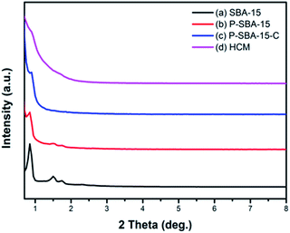 | ||
| Fig. 2 XRD patterns of the as-synthesized silica and carbon samples (a) SBA-15, (b) P-SBA-15, (c) P-SBA-15-C, (d) HCM-20. | ||
Additionally, various P-containing samples have been also characterized by N2 adsorption. The corresponding N2 adsorption isotherms and pore size distribution are displayed in Fig. S1, ESI.† The results derived from N2 adsorption revealed a decrease in the textural properties with increase of phosphorus incorporated in SBA-15 (summarized in Table S1, ESI†). Moreover, the P-containing porous template was coked in the mixture of isobutene and formaldehyde at 300 °C for 1 h, leading to the carbon coated silica composites P-SBA15-C, which exhibits an weak diffraction peak assignable to the (100) plane because of pore filling. Alternatively, this phenomenon indicates the regular mesoporous skeleton of silica is seriously broken down in the carbonization process. It is probably that formaldehyde (37 wt% in H2O) was used as carbon precursor and mesostructured silica had relatively low hydrothermal stability attributed to the amorphous nature of the pore walls.27 Unfortunately, after removal silica template, the HCM-20 displays slight distinguishable diffraction. It is suggested that it don't yield faithful carbon replicas of the mesoporous silica by using carbon sources isobutene and formaldehyde, though in mild carbonization conditions. As seen, degree of structural ordering of HCM are lower compared with the CMK-n replica. It should be therefore concluded that hydrated carbon precursor filled mesochannels of SBA-15 exhibits a low degree of structural ordering during the high temperature carbonization.28
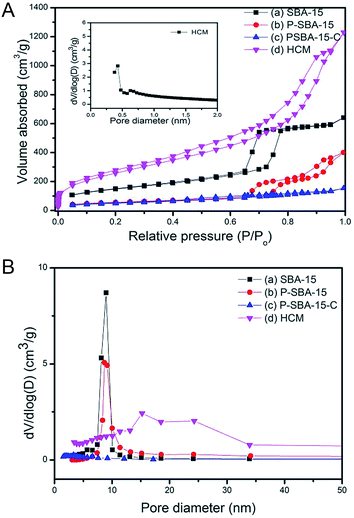
Fig. 3 shows the N2 adsorption–desorption isotherms at −196 °C and Barrett–Joyner–Halenda (BJH) pore-size distributions of as-made mesoporous silica and porous carbonaceous materials. The isotherms of SBA-15 and P-SBA-15 are identified as type IV isotherms with obvious H2-type hysteresis loops (Fig. 3a), as reported by other literatures.26,29 In addition, the phosphorus modified mesoporous SBA-15 exhibits lower N2 up take than SBA-15, this phenomenon can be attributed to damage to the ordered mesoporous framework in some extent when phosphorus was inserted the silica matrix, as verified by XRD patterns.26 The calculated textural parameters of synthesized samples are summarized in Table 1. A decrease in specific surface area and pore volume was observed after P-modification and carbonization process. The sample P-SBA-15-C with carbon deposition displays typical type-I isotherms with low N2 uptake at high relative pressure, indicating the mesopores was occluded of the mesopore channels by coke or ordered mesoporous structure collapsed seriously in the process of the carbonization. However, it is interesting to note that the HCM-20 sample reaches the highest specific surface area after removal of silica. The obtained HCM also displays typical type IV isotherms and narrow hysteresis at P/P0 = 0.45–0.9 as well as a higher nitrogen adsorption capacity in a low relative pressure region which implies the formation of the hierarchically porous structure (micropores and mesopores).
Compared with pristine SBA-15, HCM shows a wide distribution of mesopores from 15 to 24 nm resulted from disordered mesophase (Fig. 3b), as confirmed by TEM images (Fig. 5). These values are higher than the ones measured for carbons prepared from conventional precursors, such as furfuryl alcohol (around 3 nm).30 The results calculated by non-local density functional theory (NL-DFT) in Fig. S2, ESI† confirm that the pore sizes of HCM-20 distribute present more compelling evidence for the formation of hierarchical pores from 1.2 nm to 20 nm. Moreover, its Brunauer–Emmett–Teller (BET) surface area reached to 971 m2 g−1 and the total pore volume was up to 1.91 cm3 g−1 (Table 1). The higher specific surface area and larger pore volume were potential in application of absorption, energy storage and catalysis.31 The results of TG analysis of silica and coke derived samples are shown in Fig. 4. Compared with that of the primary silica template, both of the coked samples show a major weight loss within the temperature range of 350–600 °C, which should correspond to the decomposition of coke.23,31 Coking of P-SBA-15 in the mixture of isobutene and formaldehyde leads about 33 wt% coke content. Removal of silica by treatment of the P-SBA-15-C catalyst in aqueous HF solution confirms few amount of silica residue. HCM-20 showed the complete loss of weight in air at 573 °C during the thermogravimetric analysis, due to the combustion of carbon. Further study suggest that the coke amounts are relative to several conditions, such as type of support and the ratio of olefin/aldehyde.21
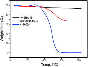 | ||
| Fig. 4 TG-DTA curves of silica and hierarchical porous carbonaceous samples (a) SBA-15, (b) P-SBA-15-C, (c) HCM-20. Measured in flow of air. | ||
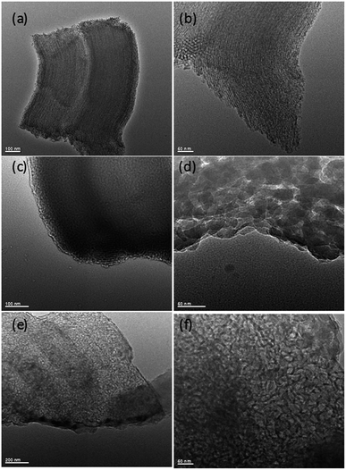 | ||
| Fig. 5 TEM images of silica and hierarchical porous carbonaceous samples (a) and (b) SBA-15, (c) and (d) P-SBA-15-C, (e) and (f) HCM-20. | ||
Fig. 5 gives the TEM images of as-synthesized mesoporous silica and carbon derivatives. The structures of SBA-15 were arranged with long-range hexagonal order over the entire region of the sample.32 However, the composites with coke displayed a wormlike channel or nano particles morphology. This result indicates that the P-SBA-15 might be destroried by the coked reaction. In particular, P-modified SBA-15 was confirmed inefficient structural stability, results of carbon replica didn't show a highly ordered structure carbonaceous material.29 Interestingly, HCM-20 demonstrates abundant mesopores in the range of 10–30 nm without external carbon deposition after the removal of the silicate framework by HF etching, the structure of this material consists of rather randomly distributed interconnected mesopores obtained by imprinting porous silica templates. Fig. 6 shows FT-IR spectra of SBA-15, P-SBA-15 and their derived carbonaceous materials, the parent SBA-15 and P-modified SBA-15 material exhibited absorption bands at 460, 806 and 1084 cm−1. The most intense band at 1084 cm−1 could be attributed to the asymmetric Si–O–Si stretch and the band at 806, 460 cm−1 can be ascribed to symmetric Si–O–Si stretch and the bending modes of P–O–P, Si–O–P and O–P–O units in P-SBA-15 sample, PO43− tetrahedral unit were hard to identify because of the overlapping of the absorption bands of the silica matrix.26,29,33 For derived carbonaceous samples, several additional peaks are observed and the characteristic adsorption peaks for the stretching of saturated C–H (2921 cm−1, 2852 cm−1, 1447 cm−1, 1376 cm−1).34
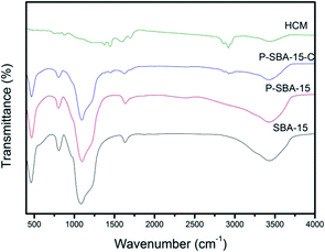 | ||
| Fig. 6 The FT-IR spectra of as-synthesized silica and hierarchical porous carbonaceous samples (a) SBA-15, (b) P-SBA-15, (c) P-SBA-15-C, (d) HCM-20. | ||
To gain further insight into the formation of coke deposits on solid catalysts, we have prepared a number of carbonaceous materials by varying template phosphorous content. The highest amounts of coke are formed in the sample of P-SBA-15 with 15–20 wt% H3PO4 (as shown in Fig. S3, ESI†), because these solid catalysts show the highest activity condensation of formaldehyde and isobutene as well as highest amount of coke being accumulated, as ascribed by literature.23
TEM images of carbonaceous materials obtained from P-SBA-15 with various amount of phosphorus are shown in Fig. 7. The micrographs clearly confirm that the ordered structural arrangement characteristic for SBA-15 is hardly preserved in obtained carbonaceous samples. One possible reason is that solid catalysts with various phosphorous contents have different reactivities of Prins reaction and resulting coke contents. The other may due to the destruction of the regular structural of pristine SBA-15 when in the incorporation of phosphorus or coke reaction process. It is worth nothing that the sample HCM-15, HCM-20 and HCM-40 exhibit mesoporous structure with diameter around 5–30 nm. However, HCM-10 exhibits non-porous structure, confirming the absence of large amount of cokes formed inside the silica pores. Nitrogen adsorption study of HCM-n was carried out to determine textural properties of porous materials, such as surface areas and pore structure (Fig. 8), HCM-n demonstrated hysteresis loops except HCM-10, which are the characteristics of mesoporous materials, and the pore diameter are 3.8 nm, 8.3 nm and 15.2 nm, respectively. Above all, porous carbonaceous materials with tunable pore structure can be made by simply controlling the P content of templates.
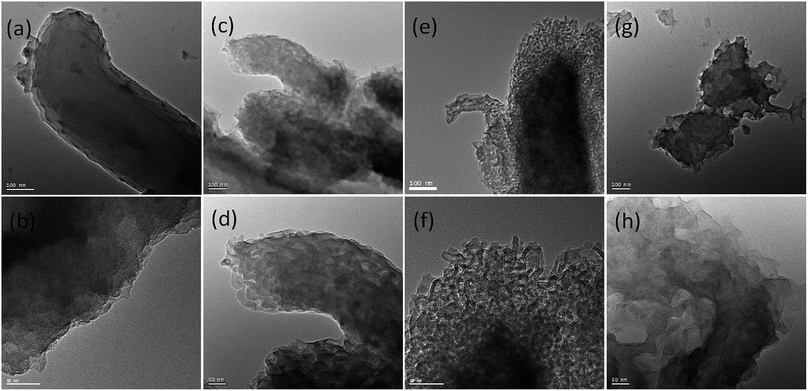 | ||
| Fig. 7 TEM images of HCM-n (n = 10, 15, 20, 40) obtained from silica template with various amount of phosphorus (a) and (b) 10%, (c) and (d) 15%, (e) and (f) 20%, (g) and (h) 40%. | ||
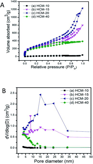 | ||
| Fig. 8 N2 adsorption isotherms (A) and corresponding pore size distribution (B) of porous carbonaceous samples (a) HCM-10, (b) HCM-15, (c) HCM-20, (d) HCM-40. | ||
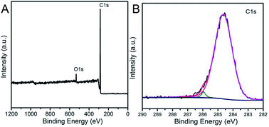
In order to investigate the elementary composition of as-prepared porous carbonaceous samples, X-ray photoelectron spectroscopy (XPS) was conducted to characterize the chemical composition of porous carbons (Fig. 9). Two peaks at the binding energies of approximately 285 and 533 eV assigned respectively to C1s, O1s can be obvious observed, proving that the HCM was composed of carbon and oxygen elements with no evidence of any other elements. In addition, the broad signal of high-resolution C1s could be fitted and deconvoluted into three peaks (284.6, 286.2 and 287.1 eV), which could be assigned to pure graphitic or amorphous C–C, C–O, and C![[double bond, length as m-dash]](https://www.rsc.org/images/entities/char_e001.gif) O bonds in the HCM network.35
O bonds in the HCM network.35
Conclusion
In summary, we have demonstrated a novel synthesis strategy for preparing hierarchical carbonaceous material by Prins reaction through a hard template. Compared with conventional hard-template method, this new route mainly takes advantage of the formation of the high amount of coke during condensation of olefin/aldehyde in a gas phase at relatively low temperature. This study provides new insights into the design of porous carbonaceous materials with higher mesoporosity by using traditionally useless cokes. Additionally, the easy manipulation of the carbonization process makes this method highly favorable. The same approach can be applied to the production of microporous carbon with various template frameworks, such as USY, Beta, which will be pursued in our future research.Conflicts of interest
There are no conflicts to declare.Acknowledgements
National Natural Science Foundation of China (No. 51473156), the Key Deployment Project of the Chinese Academy of Sciences (No. KFZD-SW-401). Key Projects of Jilin Province Science and Technology Development Plan (No. 20160204028GX).Notes and references
- J. S. Yu, S. Kang, S. B Yoon and G. Chai, J. Am. Chem. Soc., 2002, 124, 9382–9383 CrossRef CAS PubMed.
- C. D. Liang, Z. J. Li and S. Dai, Angew. Chem., Int. Ed., 2008, 47, 3696–3717 CrossRef CAS PubMed.
- X. Yang, Z. Zhang, Y. Fu and Q. Li, Nanoscale, 2015, 7, 10198–10203 RSC.
- L. Liu, S. D. Xu, Q. Yu, F. Y. Wang, H. L. Zhu, R. L. Zhang and X. Liu, Chem. Commun., 2016, 52, 11693–11696 RSC.
- N. M. Bandaru and N. H. Voelcker, J. Mater. Chem., 2012, 22, 8748–8758 RSC.
- S. Wang, L. Shang, L. Li, Y. Yu, C. Chi, K. Wang, J. Zhang, R. Shi, H. Shen, G. Waterhouse, S. Liu, J. Tian, T. Zhang and H. Liu, Adv. Mater., 2016, 28, 8379–8387 CrossRef CAS PubMed.
- L. Liang, Q. C. Zhu, T. B. Wang, F. X. Wang, J. Ma, L. Q. Jing and J. M. Sun, Microporous Mesoporous Mater., 2014, 197, 221–228 CrossRef CAS.
- T. Y. Ma, L. Liu and Z. Y. Yuan, Chem. Soc. Rev., 2013, 42, 3977–4003 RSC.
- R. Ryoo, S. H. Joo and S. Jun, J. Phys. Chem. B, 1999, 103, 7743–7746 CrossRef CAS.
- J. Y. Kim, S. B. Yoon and J. S. Yu, Chem. Commun., 2003, 790–791 RSC.
- W. Xin and Y. H. Song, RSC Adv., 2015, 5, 83239–83285 RSC.
- J. Lee, J. Kim and T. Hyeon, Adv. Mater., 2006, 18, 2073–2094 CrossRef CAS.
- S. Jun, S. H. Joo, R. Ryoo, M. Kruk, M. Jaroniec, Z. Liu, T. Ohsuna and O. Terasaki, J. Am. Chem. Soc., 2000, 122, 10712–10713 CrossRef CAS.
- K. Kim, T. Lee, Y. Kwon, Y. Seo, J. Song, J. K. Park, H. Lee, J. Y. Park, H. Ihee, S. J. Cho and R. Ryoo, Nature, 2016, 535, 131–135 CrossRef CAS PubMed.
- Z. X. Ma, T. Kyotani, Z. Liu, O. Terasaki and A. Tomita, Chem. Mater., 2001, 13, 4413–4415 CrossRef CAS.
- Y. Seo, K. Kim, Y. Jung and R. Ryoo, Microporous Mesoporous Mater., 2015, 207, 156–162 CrossRef CAS.
- P. Niebrzydowska, R. Janus, P. Kustrowski, S. Jarczewski, A. Wach, A. M. S. Albero and F. R. Reinoso, Carbon, 2013, 64, 252–261 CrossRef CAS.
- H. Darmstadt, C. Roy, S. Kaliaguine, T. W. Kim and R. Ryoo, Chem. Mater., 2003, 15, 3300–3307 CrossRef CAS.
- Y. Huang, H. Q. Cai, D. Feng, D. Gu, Y. H. Deng, B. Tu, H. T. Wang, P. A. Webley and D. Y. Zhao, Chem. Commun., 2008, 2641–2643 RSC.
- K. Kim, Y. Kwon, T. Lee, S. J. Cho and R. Ryoo, Carbon, 2017, 118, 517–523 CrossRef CAS.
- I. Ivanova, V. L. Sushkevich, Y. G. Kolyagin and V. V. Ordomsky, Angew. Chem., Int. Ed., 2013, 125, 13199–13202 CrossRef.
- Z. X. Zhang, Y. H. Wang, J. M. Lu, C. F. Zhang, M. Wang, M. R. Li, X. B. Liu and F. Wang, ACS Catal., 2016, 6, 8248–8254 CrossRef CAS.
- V. L. Sushkevich, V. V. Ordomsky and I. I. Ivanova, Catal. Sci. Technol., 2016, 6, 6354–6364 CAS.
- V. L. Sushkevich, P. A. Kots, I. I. Ivanova, M. Marinova, S. Moldovan, O. Ersen and V. V. Ordomsky, Chem. Mater., 2017, 29, 2676–2680 CrossRef CAS.
- S. Kawi, S. C. Shen and P. L. Chew, J. Mater. Chem., 2012, 12, 1582–1586 RSC.
- M. Colilla, I. I. Barba and M. V. Regi, Microporous Mesoporous Mater., 2010, 135, 51–59 CrossRef CAS.
- Y. Han, W. Wu, Y. Y. Sun, D. S. Li and F. S. Xiao, Chem. Mater., 2002, 14, 1144–1148 CrossRef CAS.
- P. Niebrzydowska, R. Janus, P. Kuśtrowski, S. Jarczewski, A. Wach, A. M. Silvestre-Albero and F. Rodriguez-Reinoso, Carbon, 2013, 64, 252–261 CrossRef CAS.
- K. Yasutaka, Y. Takato, K. Takashi, M. Kohsuke and Y. Hiromi, J. Phys. Chem. B, 2011, 115, 10335–10345 CrossRef CAS PubMed.
- A. B. Fuertes and D. M. Nevskaia, Microporous Mesoporous Mater., 2003, 62, 177–190 CrossRef CAS.
- V. L. Sushkevich, I. I. Ivanova, C. Lancelot, S. Moldovan, O. Ersen and V. V. Ordomsky, Chem. Commun., 2015, 51, 17120–17123 RSC.
- D. Y. Zhao, J. L. Feng, Q. S. Huo, N. Melosh, G. H. Fredrickson, B. F. Chmelka and G. D. Stucky, Science, 1998, 279, 548–552 CrossRef CAS PubMed.
- M. V. Regi, I. I. Barba, A. Ramila, J. P. Pariente, F. Babonneau and J. M. Calbet, Solid State Sci., 2005, 7, 233–237 CrossRef.
- S. Qiu, B. Jiang, X. Zheng, J. T. Zheng, C. S. Zhu and M. B. Wu, Carbon, 2015, 84, 551–553 CrossRef CAS.
- J. Gong, J. Liu, Z. W. Jiang, X. Wen, E. Mijowska, T. Tang and X. C. Chen, J. Colloid Interface Sci., 2015, 445, 195–204 CrossRef CAS PubMed.
Footnote |
| † Electronic supplementary information (ESI) available. See DOI: 10.1039/c8ra01270a |
| This journal is © The Royal Society of Chemistry 2018 |

