 Open Access Article
Designable core–shell graphite particles for thermally conductive and electrically insulating polymer composites†
Takashi Hirahara *
*
DuPont Kabushiki Kaisha, Transportation & Advanced Polymers, 19-2 Kiyohara Kogyodanchi, Utsunomiya-shi, Tochigi 321-3231, Japan. E-mail: takashi.hirahara@dupont.com
First published on 8th May 2018
Abstract
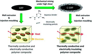
Electrically insulating graphite particles were prepared by coating graphite with electrically insulating materials via a two-step mechanical mixing process. Graphite particles were treated with a binder in the 1st mixing process and coated with an electrically insulating particle in the 2nd mixing process under high shear forces within a short processing time (below 1 min). Micron-sized graphite particles were successfully coated with various inorganic particles of appropriate particle diameter. Talc and boron nitride exhibited good affinities with graphite and formed effective coating layers to render reliable electrical insulation. Graphite coated with talc and boron nitride exhibited a high volume resistivity, greater than 109 Ω cm. The insulating property was retained even after compounding and moulding the coated graphite particles with a polymer. The two-step coating process under high shear forces is a promising method for production of coated graphite particles.
Introduction
Thermally conductive materials have attracted significant attention in various fields such as electronic packaging, office automated equipment, hand held devices, and automobiles,1–5 and light emitting diode housing is one of the promising applications in terms of thermal management.6–8 Almost all of these applications require prevention of excessive temperature increase to ensure stable operation and extend product lifetime. As one of the solutions, thermally conductive materials play a key role in conducting and releasing heat to the atmosphere as part of heat sinks. The demand for thermally conductive and electrically insulating polymer composites has increased in recent times, because the use of these materials can reduce the number of components requiring electrical insulation (EI) in a device.9 Such polymer composites are promising candidates for commercial applications.10A major strategy used for achieving higher thermal conductivity (TC) of polymer composites is incorporation of an inorganic filler exhibiting high TC for the formation of networks that can conduct heat in the polymer.11,12 Generally, the TC values of composites depend strongly on the filler and its content. Filler reinforced polymer composites usually exhibit approximately ten times higher TC than unreinforced polymers (∼0.3 W m−1 K−1).13 However, the type of electrically insulating fillers for efficient heat conduction is limited to conventional fillers such as aluminium oxide (Al2O3), magnesium oxide (MgO), and boron nitride (BN).14–16 Therefore, it is difficult to obtain good composite performance by material design. BN is a well-known conventional filler that can provide EI; however, it shows a moderate TC of approximately 60 W m−1 K−1 and has disadvantages of high cost and compounding difficulty at high contents.17 Alternative materials such as aluminium nitride (AlN) and beryllium oxide (BeO) exhibit both high TC and good EI, but, they are disadvantageous because of the hygroscopic nature of the former and the hazardous property of the latter.18,19 On the other hand, graphite particles (GRPs) exhibit a relatively high TC (>100 W m−1 K−1). Especially, micron-sized GRP is clearly safe and economical compared with nano-sized material such as graphene and graphite nano platelets.20,21 However, the modification is required to use GRP as electrically insulating filler because of the electrical conductivity.22 Thus, a new design is required to increase both the TC and the EI properties of the filler and the polymer composite.
There has been remarkable progress in the design of thermally conductive and electrically insulating fillers and its polymeric composites such as modified BN.23–25 These materials show excellent properties, while the process applicability still needs to be considered for practical use. In the manufacturing perspective, one promising approach is to deposit an electrically insulating coating on the surface of GRPs; this method is advantageous from the view point of not only performance but also process cost. However, a coating layer usually prevents direct contact between the GRPs, resulting in a slight decrease in the TC. For selecting coating materials without limitation, thermally conductive paths can be formed by controlling the coating morphology. Furthermore, process-related and economic issues can be solved using this concept. This freedom of coating design is important to realise the concept of electrically insulating GRPs for practical applications.
Several methods have been adopted to obtain electrically insulating GRPs with high volume resistivity and high TC.26–28 For instance, it has been reported that chemically deposited silica coatings on GRPs show good volume resistivity;29–31 however, the application of this type of coated GRP (C-GRP) is limited to thermosetting resins because of the brittleness of the coating layer. The brittleness must be reduced to extend the applications of GRPs to thermoplastic resins in terms of manufacturing. Especially, thermally conductive thermoplastic resins for injection moulding is usually compounded with a large amount of filler to achieve a high TC. The filler is subject to high shear forces during melt extrusion processes; thus, the coating layer is likely to be broken, depending on the filler content and the adhesion between the fillers and the coating layers.32 This tendency becomes stronger for large-sized GRPs. A thicker coating layer is one of the solutions to reduce brittleness. However, the TC of the coated filler will decrease if the TC of the coating layer is low. Therefore, the silica coating method cannot balance the brittleness and the TC performance, because the coating layer is limited to silica produced by specific chemical methods. A coating layer consisting of other inorganic particles is preferred to overcome the brittleness and balance the TC and the EI.
In this study, we adopted the mechanical mixing method to obtain electrically insulating GRPs for melt extrusion and injection moulding. The mechanical mixing method can overcome the limitation of coating material selection; therefore, it is possible to obtain higher TC and volume resistivity of the coated filler and the polymer composite. We used mechanofusion as the coating process owing to its advantages of (1) effective high-speed mixing, (2) short operating time, and (3) high-shearing condition. Especially, a high-shear condition forces the filler to be stiff; hence, it can endure the shearing condition during compounding with a polymer. The mechanofusion method has been studied for many years for the preparation of unique fillers in the particle technology field.33–35 This method can be used to prepare a wide range of hybrid fillers with unique morphologies, such as coated fillers, embedded fillers, and combined fillers. Generally, the morphology of a filler can be controlled by the particle size and the operating condition. It is necessary to select relatively large GRPs to achieve high TC values; but larger GRPs tend to be more brittle than smaller ones. This trade-off relation is a bottleneck to obtain practically applicable C-GRP. In the novel study, we carried out mechanically multiple-step processes to meet the EI requirement of designable core–shell GRPs for injection mouldable polymer composites.
Experimental
Materials and methods
Characterisation
| λ (W m−1 K−1) = α (mm2 s−1) × Cp (J g−1 K−1) × ρ (g cm−3) |
Results and discussion
Electrically insulating coating process for GRP
The target morphology for EI is a uniform coating of particles on the surface of GRP. It has been reported that round shaped particles can be easily coated with other particles by mechanical processes.36 On the other hand, it is difficult to coat platy particles by mechanical mixing processes such as mechanofusion. The difficulty in coating depends on the coating material and its ratio in the target particle. The content of coating particles should be less to exploit the excellent TC performance of a core GRP. Therefore, in the present study, a small amount of liquid binder was used to obtain a liquid bridge force, because a simple dry mixing did not produce a uniform coating experimentally. We considered two systems to realise the coating morphologies: (i) GRP/binder and (ii) GRP/binder/coating particle. In addition, we carried out two processes to clarify their effect on filler morphology and the corresponding volume resistivity: (a) facile one-step mixing process with all the constituents and (b) an effective two-step process comprising 1st mixing of GRP/binder and 2nd mixing of coating particle. Table 1 shows the compositions of the samples and the details of the high-shear mixing conditions. Three types of C-GRP were prepared, and their morphologies were studied after processing. We selected GRP X100 (D50: 136 μm) as a starting material to investigate the effect of coating process. The methylol melamine aqueous solution was used as a binder for the GRP and the coating particles because of the good affinity of melamine moiety on the π conjugation of the GRP surface.37 Prior to evaluation, the binder was converted to melamine resin after curing the obtained C-GRP. A submicron-sized mineral particle talc HTP Ultra 5 (D50: 0.6 μm) was used as the 1st candidate particle as it has a large surface area for an effective coating. Samples C-GRP 1, C-GRP 2, and C-GRP 3 were prepared by the combination of processes (i)/(a), (ii)/(a), and (ii)/(b), respectively.| C-GRP 1 | C-GRP 2 | C-GRP 3 | |
|---|---|---|---|
| GRP/g (vol%) | 70 (91.3) | 70 (72) | 70 (72) |
| Methylol melamine/g (vol%) | 4.2 (8.7) | 4.2 (7) | 4.2 (7) |
| Talc/g (vol%) | — | 25 (21) | 25 (21) |
| Rotating speed/rpm | 3000 | 3000 | 3000 |
| 1st mixing time/min | 5 | — | 5 |
| 2nd mixing time/min | — | 0.5 | 0.5 |
Fig. 1 shows the SEM images of raw GRP, C-GRP 1, C-GRP 2, and C-GRP 3. C-GRP 1 retained the platy morphology even after mixing, similar to that of raw GRP. C-GRP 2 also exhibited a platy morphology; however, the particle size was smaller than that of raw GRP. The reduced particle size of C-GRP 2 can be attributed to fragmentation of large GRPs by the mechanical shearing process.38 In Fig. 1(c), the grey regions represent GRP/binder, whereas the white regions represent talc in C-GRP 2. The contrast is not uniform, which indicates that the talc particles are not coated uniformly. A possible reason is the intermixing of the talc particles and the GRP fragments, which limits the amount of talc on the surface coating. On the contrary, C-GRP 3 exhibited uniform white regions on the surface of each particle, which indicates that C-GRP 3 is well coated among all the samples with the similar average particle diameter to that of raw GRP (Fig. S1, ESI†). To evaluate its shear resistance, C-GRP 3 was compounded with the PBT polymer using a twin screw extruder under an average shear rate of 33 s−1 and moulded as a plate (C-GRP 3 : 26 vol%) by the injection process. Fig. 2(a) represents the cross-sectional images of the moulded plate of C-GRP 3. The talc coating layer is still observed as white regions around the GRP core represented by black regions. The fine talc particles possibly contribute to the high breakage energy of C-GRP 3, supported by breakage simulation of core–shell particles.39 For further confirmation of the morphology, the polymer moiety in the plate was removed by curing at 500 °C for 1 h in air. The morphology of C-GRP 3 is almost similar to that before the melt extrusion and the moulding processes. This fact indicates that C-GRP 3 has enough shear resistance to retain the coating layer during the melt extrusion process.
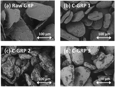 | ||
| Fig. 1 SEM images of (a) raw GRP, (b) C-GRP 1, (c) C-GRP 2, and (d) C-GRP 3 mixed by the high-shear mixing process. | ||
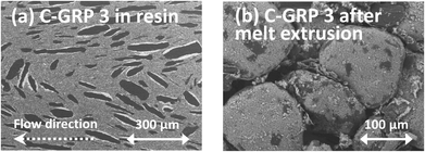 | ||
| Fig. 2 Cross-sectional SEM images of the (a) moulded resin plate containing C-GRP 3 and (b) the C-GRP 3 morphology after the removal of resin moiety by curing at 500 °C for 1 h in air. | ||
We evaluated the volume resistivity of each particle to clarify the coating effect. Fig. 3 shows the volume resistivity of raw GRP and the different C-GRP samples in the compressed particle form. The volume resistivity of C-GRP 1 increased from 6 to 15 Ω cm. This result suggests that the binder component contributes to EI on the surface of the GRP core. C-GRP 2 exhibited a volume resistivity of 103 Ω cm, which is hundred times higher than that of C-GRP 1. This improvement is attributed to the decrease in the content of GRP, from 91.3 vol% in C-GRP 1 to 72 vol% in C-GRP 2. The SEM image of C-GRP 2 indicates that the some talc particles are exposed to the surface of GRP, which is the morphologic effect on EI. The volume resistivity of C-GRP 3 was approximately 109 Ω cm. The SEM image of C-GRP 3 supports the notion that the coating layer plays an important role in preventing contact between the GRP cores. These results indicate that the two-step mechanical mixing process can be used to prepare well-coated particles with a high volume resistivity.
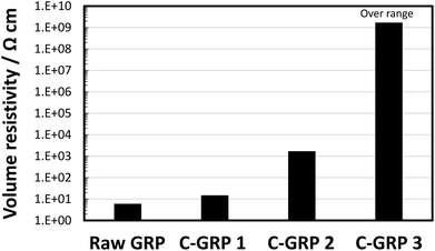 | ||
| Fig. 3 Volume resistivity of raw GRP, C-GRP 1, C-GRP 2, and C-GRP 3 prepared by the mechanofusion process. | ||
To clarify the effect of the composition of C-GRP on the volume resistivity, we varied the contents of the binder and the coating particle. The methylol melamine aqueous solution (concentration: 0.42 g mL–1) and talc HTP Ultra 5 (D50: 0.6 μm) particles were used as the binder and the coating particle, respectively. Fig. 4 shows the volume resistivity of C-GRP as a function of the talc content. At 4 vol% binder content, the volume resistivity is saturated at 8 vol% talc content, exhibiting a value of 106 Ω cm. On the other hand, the C-GRP containing 8 vol% binder exhibited a volume resistivity of approximately 109 Ω cm at 12 vol% talc content. This result indicates that the high volume resistivity of C-GRP is related to not only the amount of talc but also the existence of the binder. Considering the effect of coating, the increase in the volume resistivity is mainly attributed to the prevention of physical contact rather than quantum mechanical effect of electron tunneling via increase in the average distance between the GRP cores.40
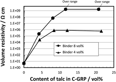 | ||
| Fig. 4 Volume resistivity of C-GRP prepared by the two-step mixing process as a function of talc content in C-GRP. | ||
The most attractive advantage of mechanical coating is the freedom of coating design; the selection of coating material is critical to both TC and EI properties. We coated GRP with various particles to investigate the effect of the types of coating particle on the high volume resistivity of C-GRPs. Fig. 5 shows the SEM images of GRP coated with typical inorganic particles, such as talc (D50: 2 μm), sericite (D50: 2 μm), mica (D50: 5 μm), boemite (D50: 3 μm), BN (D50: 4 μm), titanium dioxide (TiO2) (D50: 0.23 μm), and calcium difluoride (CaF2) (D50: 6 μm). The names of the samples coated with different coating particles are prefixed with C-GRP@, e.g., C-GRP@talc. The volume percentage of the coating particle was fixed at 21 (binder content: 7 vol%), which is higher than the threshold value for the highest volume resistivity in Fig. 4. This is because, a thicker shell enhances the breakage stress of the core shell particles.41 As shown in the image of C-GRP@talc (Fig. 5(a)), the micron-sized talc particles are coated uniformly, similar to the case of C-GRP 3 shown in Fig. 1(d). The other minerals such as sericite, mica, and boemite also covered the GRP surface; however, the adhesion of these particles to the surface was insufficient as evident from the surface roughness. Among the particles of simple compositions, the BN particle covered the GRP surface more uniformly compared with TiO2 and CaF2. This difference may be attributed to the affinity difference resulting from the crystal structures of GRP and the coated particle; the two dimensional crystal structure of talc and BN are similar to that of GRP.
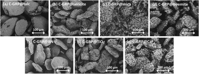 | ||
| Fig. 5 SEM images of GRP coated with (a) talc, (b) sericite, (c) mica, (d) boemite, (e) BN, (f) TiO2, and (g) CaF2 particles. | ||
Fig. 6 shows the volume resistivity of GRP coated with various particles as compressed forms. C-GRP@talc and C-GRP@BN exhibited the highest volume resistivity among all the C-GRPs, greater than approximately 109 Ω cm. Coating with sericite, mica, and boemite also resulted in a relatively high volume resistivity of the corresponding C-GRP, with values greater than 107 Ω cm. On the other hand, C-GRP@TiO2 and C-GRP@CaF2 exhibited the lowest volume resistivity, less than 103 Ω cm. The smooth coating surfaces of C-GRP@talc and C-GRP@BN are believed to have conduced to the high volume resistivity. The rough coating surfaces of the other C-GRPs possibly caused contact between the GRP cores in their pressed form during evaluation, thereby reducing the volume resistivity. An exception is the behaviour of C-GRP@TiO2. The average diameter of TiO2 is only 0.2 μm which can contribute to a better coating; however, the volume resistivity of C-GRP@TiO2 is less than 103 Ω cm. The round shape of the TiO2 particles appears to be unsuitable for the coating, because of the lesser contact area on the GRP surface when compared with platy particles. These results indicate that a better coating morphology leads to a higher volume resistivity.
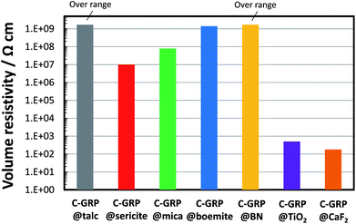 | ||
| Fig. 6 Volume resistivity of GRP coated with talc, sericite, mica, boemite, BN, TiO2, and CaF2 particles. | ||
The obtained C-GRP samples were compounded with a polyester polymer and moulded into a plate to measure the volume resistivity and the TC. The volume resistivities of the polymer composites were evaluated along the direction of the thickness, because the moulded parts are usually used for electrical safety along this direction. The platy C-GRP is oriented along the in-plane direction during injection moulding; therefore, the surface coverage of the GRP core is critical to achieve a high volume resistivity in terms of possibility of contact. The content of C-GRPs in the composites were fixed at 26 vol%, which is higher than the typical percolation threshold of approximately 11 vol%, for electrical conductivity.42 Table 2 shows the volume resistivity of each plate at 100, 250, 500, and 1000 V. The measurements were continued until the volume resistivity was out of range. The moulded plate containing raw GRP exhibited the lowest volume resistivity, <106 Ω cm at 100 V. On the other hand, the moulded plates of C-GRP@talc and C-GRP@BN exhibited the highest volume resistivity, >1014 Ω cm at 1000 V. These results indicate that the coating layers of talc and BN render effective EI even after the melt extrusion and the moulding processes. In other words, these C-GRP samples exhibit strong shear resistance to retain the particle morphology and its function. The lubrication properties of talc and BN particles may also contribute to the improved shear resistance of C-GRP compared to the other coating particles.43,44 The force of screws during the melt blending process also support the difference in the lubrication properties (Fig. S2, ESI†). The plates containing C-GRP@sericite or C-GRP@boemite exhibited moderate volume resistivity compared to that as particles. However, the plate containing C-GRP@mica was electrically conductive in spite of the relatively high volume resistivity of the compressed particle. The mismatch in the volume resistivity of different forms possibly results from delamination of the coating layer during the melt extrusion and the moulding processes. The plates containing C-GRP@TiO2 or C-GRP@CaF2 were electrically conductive even at 100 V, similar to the evaluation results for their compressed particle forms. These results for moulded plates suggest that the concept of coating with electrically insulating particles is effective not only in press moulding but also for melt extrusion and injection moulding processes, depending on the type of the coating particle.
| Volume resistivity/Ω cm | ||||
|---|---|---|---|---|
| 100 V | 250 V | 500 V | 1000 V | |
| Raw GRP | <106 | — | — | — |
| C-GRP@talc | >1012 | >1012 | >1013 | >1014 |
| C-GRP@sericite | >1012 | >1012 | <107 | — |
| C-GRP@mica | <106 | — | — | — |
| C-GRP@boemite | >1012 | <106 | — | — |
| C-GRP@BN | >1012 | >1012 | >1013 | >1014 |
| C-GRP@TiO2 | <106 | — | — | — |
| C-GRP@CaF2 | <106 | — | — | — |
Fig. 7 presents the relation between the TC of the plate containing C-GRPs and the volume resistivity of C-GRPs as particles. The TC properties were measured along the in-plane direction, because the moulded parts are frequently used as an in-plane heat spreader in practical applications. Each TC value was expressed as relative percentage versus the TC value of the plate containing raw GRP. The content of C-GRP was fixed at 26 vol% in all the polymer composite plates. The TC of the plate containing C-GRP 1 was moderate, because the content of GRP was decreased to 91.3 vol% in C-GRP 1. The TC of the methylol melamine binder is less than 0.3 W m−1 K−1; therefore, this could function as a thermal insulator in the particle. The cores of all the C-GRPs were composed of C-GRP 1 and affected by the binder (binder content: 7 vol% in C-GRPs except for C-GRP 1). Three types of C-GRP@talc (D50 of talc: 0.6 μm) were prepared at various GRP contents, and the TC values of their moulded polymer composite plates were evaluated. The different contents of raw GRP core in C-GRP@talc were 87, 81, and 72 vol%, with 7 vol% binder in each case. The TC value of the composite plate gradually decreases by up to 10% with increase in the volume resistivity by 104 Ω cm. This is attributed to the combined effect of increase in the raw GRP content and prevention of contact between the raw GRP cores. The moulded plate containing C-GRP@sericite, C-GRP@mica, and C-GRP@boemite retained their TC values at 53, 60, and 66% respectively. In the cases of C-GRP@TiO2 and C-GRP@CaF2, the retention percentages of TC value were 69 and 62%, respectively which are relatively high compared to that of others. The trend between the TC value and the volume resistivity indicates the difference in the contact of the GRP core in a polymer composite plate. To investigate the effect of particle diameter on TC of the polymer composites, three types of C-GRP namely, C-GRP@BN1, C-GRP@BN2, and C-GRP@BN3 were prepared. The average particle diameter (D50) of BN1, BN2, and BN3 were 4, 8, and 18 μm, respectively. The retention values of TC were 55, 64, and 64%, respectively in C-GRP@BN1, C-GRP@BN2, and C-GRP@BN3. Among them, C-GRP@BN2 exhibited the highest volume resistivity, greater than 109 Ω cm. On the whole, a weak trade-off relation is observed between the TC and the volume resistivity at the same content of raw GRP. This relation is mainly because of the prevention of GRP contact via a coating layer. This prevention causes a phonon scattering at the coating interface, resulting in a lower TC like in the case of nanocomposites.45 On the other hand, the retention of the TC value depends on the type of the coating layer in the range of high volume resistivity, above 109 Ω cm. It is reasonable that the TC difference of the coating layer affects the TC of the moulded plate. Especially, the TC of talc is only 2 W m−1 K−1, whereas that of BN is approximately 60 W m−1 K−1. This fact indicates that BN is a more suitable thermal conductor for C-GRP compared with talc.
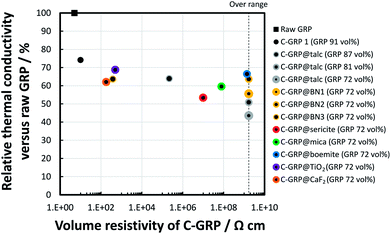 | ||
| Fig. 7 Relative thermal conductivity of the polymer composites containing C-GRPs at 26 vol% filler loading versus raw GRP as a function of the volume resistivity of the C-GRPs. | ||
Conclusions
We prepared electrically insulating GRPs coated with various particles via an efficient high-shear mixing process. The most promising mixing process comprised a two-step process: mixing of (i) GRPs with a small amount binder as a pre-filler and (ii) pre-filler with various electrically insulating particles. The obtained particles were sufficiently stiff to process the melt extrusion with a polymer. The cross-sectional images of the polymer composites exhibited that the coating layer was retained after the melt extrusion and the injection moulding processes. Especially, C-GRP@talc and C-GRP@BN exhibited a high volume resistivity, both in the form of compressed particles and polymer composites. The polymer composites had a weak tendency to show lower TC values at higher volume resistivity of C-GRP. The two-step synthesis process of C-GRP can be extended to the fabrication of unique hybrid fillers for melt extrusion with polymers. The obtained C-GRP is useful for thermally conductive and electrically insulating polymer composites for injection moulding.Conflicts of interest
There are no conflicts to declare.Acknowledgements
This work was partially supported by New Energy and Industrial Technology Development Organization (NEDO) based on the strategic program for innovative energy efficiency technology, 14102124-0.Notes and references
- C. P. Wong and R. S. Bollampally, J. Appl. Polym. Sci., 1999, 74, 3396 CrossRef CAS.
- E. M. C. Wong, IEEE Transactions on Consumer Electronics, 1994, 40, 28 CrossRef.
- S. P. Gurrum, D. R. Edwards, T. Marchand-Golder, J. Akiyama, S. Yokoya, J.-F. Drouard and F. Dahan, IEEE 62nd Electron. Compon. Technol. Conf., 2012, p. 1488 Search PubMed.
- N. Saba, P. M. Tahir and M. Jawaid, Polymers, 2014, 6, 2247 CrossRef.
- H. Chen, V. V. Ginzburg, J. Yang, Y. Yang, W. Liu, Y. Huang, L. Du and B. Chen, Prog. Polym. Sci., 2016, 59, 41 CrossRef CAS.
- Y. V. Trofimov, S. I. Lishik and P. P. Pershukevich, Semicond. Phys., Quantum Electron. Optoelectron., 2013, 16, 198 CrossRef CAS.
- M.-H. Chang, D. Das, P. V. Varde and M. Pecht, Microelectron. Reliab., 2012, 52, 762 CrossRef.
- X. Perpinñà, R. J. Werkhoven, M. Vellvehi, J. Jakovenko, X. Jordà, J. M. G. Kunen, P. Bancken and P. J. Bolt, IEEE Xplore: IEEE Transactions on Power Electronics, 2015, 30, 3876 CrossRef.
- I. Pleşa, P. V. Noţingher, S. Schlögl, C. Sumereder and M. Muhr, Polymers, 2016, 8, 173 CrossRef.
- M. A. Vadivelu, C. R. Kumar and G. M. Joshi, Compos. Interfaces, 2016, 23, 847 CrossRef CAS.
- S. M. Lebedev and O. S. Gefle, Appl. Therm. Eng., 2015, 91, 875 CrossRef CAS.
- C. Feng, H. Ni, J. Chen and W. Yang, ACS Appl. Mater. Interfaces, 2016, 8, 19732 CAS.
- M. Shtein, R. Nadiv, M. Buzaglo, K. Kahil and O. Regev, Chem. Mater., 2015, 27, 2100 CrossRef CAS.
- S. Zhang, X. Y. Cao, Y. M. Ma, Y. C. Ke, J. K. Zhang and F. S. Wang, eXPRESS Polym. Lett., 2011, 5, 581 CrossRef CAS.
- A. A. Wereszczak, T. G. Morrissey, C. N. Volante, P. J. Farris Jr., R. J. Groele, R. H. Wiles and H. Wang, IEEE Trans. Compon., Packag., Manuf. Technol., 2013, 3, 1994 CrossRef CAS.
- C. Yuan, B. Duan, L. Li, B. Xie, M. Huang and X. Luo, ACS Appl. Mater. Interfaces, 2015, 7, 13000 CAS.
- Z. Lin, A. Mcnamara, Y. Liu, K.-S. Moon and C.-P. Wong, Compos. Sci. Technol., 2014, 90, 123 CrossRef CAS.
- J. Li, M. Nakamura, T. Shirai, K. Matsumaru, C. Ishizki and K. Ishizaki, J. Am. Ceram. Soc., 2006, 89, 937 CrossRef CAS.
- G. P. Akishin, S. K. Turnaev, V. Y. Vaispapir, M. A. Gorbunova, Y. N. Makurin, V. S. Kiiko and A. L. Ivanovskii, Refract. Ind. Ceram., 2009, 50, 465 CrossRef CAS.
- X. Cai, Z. Jiang, X. Zhang, T. Gao, K. Yue and X. Zhang, RSC Adv., 2018, 8, 11367 RSC.
- J. Gu, C. Liang, X. Zhao, B. Gan, H. Qiu, Y. Guo, X. Yang, Q. Zhang and D.-Y. Wang, Compos. Sci. Technol., 2017, 139, 83 CrossRef CAS.
- A. K. Pandey, R. Kumar, V. S. Kachhavah and K. K. Kar, RSC Adv., 2016, 6, 50559 RSC.
- D. Kim, S. Ha, H. K. Choi, J. Yu and Y. A. Kim, RSC Adv., 2018, 8, 4426 RSC.
- X. Yang, L. Tang, Y. Guo, C. Liang, Q. Zhang, K. Kou and J. Gu, Composites, Part A, 2017, 101, 237 CrossRef CAS.
- T. Morishita and N. Takahashi, RSC Adv., 2017, 7, 36450 RSC.
- R. Qian, J. Yu, C. Wu, X. Zhai and P. Jiang, RSC Adv., 2013, 3, 17373 RSC.
- X. Pu, H.-B. Zhang, X. Li, C. Gui and Z.-Z. Yu, RSC Adv., 2014, 4, 15297 RSC.
- D. Tang, J. S. Q. Yang, M. Kong, Z. Zhao, Y. Huang, X. Liao and Y. Liu, RSC Adv., 2015, 5, 55170 RSC.
- S. Choi, Y. Kim, J. H. Yun, I. Kim and S. E. Shim, Mater. Lett., 2013, 90, 87 CrossRef CAS.
- S. Choi, K. Kim, J. Nam and S. E. Shim, Carbon, 2013, 60, 254 CrossRef CAS.
- Y. Kim, Y. Qian, M. Kim, J. Ju, S.-H. Baeck and S. E. Shim, RSC Adv., 2017, 7, 24242 RSC.
- Y. Noma, Y. Saga and N. Une, Carbon, 2014, 78, 204 CrossRef CAS.
- M. Alonso, M. Satoh and K. Miyanami, Powder Technol., 1989, 59, 45 CrossRef CAS.
- R. Pfeffer, R. N. Dave, D. Wei and M. Ramlakhan, Powder Technol., 2001, 117, 40 CrossRef CAS.
- C.-S. Chou, R.-Y. Yang, M.-H. Weng and C.-H. Yeh, Powder Technol., 2008, 187, 181 CrossRef CAS.
- A. Mujumdar, D. Wei, R. N. Dave, R. Pfeffer and C.-Y. Wu, Powder Technol., 2004, 140, 86 CrossRef CAS.
- A. E. D. Rio-Castillo, C. Merino, E. Díez-Barra and E. Vázquez, Nano Res., 2014, 7, 963 CrossRef CAS.
- M. Yi and Z. Shen, J. Mater. Chem. A, 2015, 3, 11700 CAS.
- M. Weber, A. Spettl, M. Dosta, S. Heinrich and V. Schmidt, Comput. Mater. Sci., 2017, 137, 100 CrossRef CAS.
- J.-F. Zou, Z.-Z. Yu, Y.-X. Pan, X.-P. Fang and Y.-C. Ou, J. Polym. Sci., Part B: Polym. Phys., 2002, 40, 954 CrossRef CAS.
- M. O'Sullivan, Z. Zhang and B. Vincent, Langmuir, 2009, 25, 7962 CrossRef PubMed.
- I. Krupa, I. Novák and I. Chodák, Synth. Met., 2004, 145, 245 CrossRef CAS.
- J. K. Katiyar, S. K. Sinha and A. Kumar, Wear, 2016, 362–363, 199 CrossRef CAS.
- Y. Kimura, T. Wakabayashi, K. Okada, T. Wada and H. Nishikawa, Wear, 1999, 232, 199 CrossRef CAS.
- W. Tian and R. Yang, Computer Modeling in Engineering and Sciences, 2008, 24, 123 Search PubMed.
Footnote |
| † Electronic supplementary information (ESI) available. See DOI: 10.1039/c8ra01946k |
| This journal is © The Royal Society of Chemistry 2018 |

