 Open Access Article
Enhancement of dielectric constant of polyimide by doping with modified silicon dioxide@titanium carbide nanoparticles
Tong Zhang ,
Bao-Jun Han,
Juan Yu,
Xiao-Dong Wang and
Pei Huang*
State Key Laboratory of Materials-Oriented Chemical Engineering, College of Chemical Engineering, Nanjing Tech University, Nanjing 210009, P. R. China. E-mail: phuang@njtech.edu.cn
First published on 8th May 2018
Abstract
Electrode materials used in supercapacitors must have a high dielectric constant and a low dielectric loss along with good mechanical properties. In this study, the dielectric constant of polyimide (PI) was improved by preparing a PI/SiO2@TiC composite. A homogeneous dispersion of SiO2@TiC nanoparticles was obtained by the hydrolyzation of tetraethyl orthosilicate, which resulted in the formation of a thin layer of SiO2 on TiC particles. Polyamic acid was doped with the modified SiO2@TiC nanoparticles by mechanical blending to synthesize the PI/SiO2@TiC composite, and its dielectric properties were investigated. Scanning electron microscopy studies confirmed that the SiO2@TiC particles were homogeneously dispersed in the PI matrix and did not exhibit agglomeration. An increase in the SiO2@TiC filler content increased the dielectric constant and the dielectric loss of the composite, but decreased its breakdown strength and deteriorated its mechanical properties. Thus, the addition of SiO2@TiC particles to PI is suitable for improving its dielectric properties while maintaining its flexibility.
Introduction
Owing to the rapid developments in the field of electronics, miniaturization of electronic devices as well as improving their speed has become essential. This has necessitated the development of electronic components based on high-dielectric-constant materials. High-dielectric-constant materials have been widely used in various fields such as supercapacitors, aerospace, communications and so on.3 The dielectric constant refers to the ability of shifting the charge. Conventional high-dielectric-constant materials include ferroelectric ceramics and polymeric materials.1–5 When the ceramic content in a material is ≥ 50%, it has an apparent decline in another aspect of mechanical properties even though ceramic materials exhibit high dielectric constant. Compared to ceramic materials, polymeric materials are more versatile owing to their lower processing temperature, smaller dielectric loss, higher flexibility, while being environmentally or chemically resistant. In recent years, polyimide as one of the most promising materials, polymer-based composite materials with high dielectric constants have been studied extensively for use as functional materials.6 Numerous work has been reported to tap the potential of composite materials.Over the past several years, high-dielectric-constant polymer composites based on electric conductors, such as metallics, graphene and carbide have achieved great attention because of the low filler concentration and great possibility to integrate the performance advantages of polymer. Although, polymer composites based on conductor with super high-dielectric-constant have been achieved, the high dielectric loss caused by the leakage current is still an enormous challenge,7 which limits their applications. Therefore, the key issue is to prevent direct contact between conductive fillers to improve the dielectric constant and suppress dielectric loss of the polymer-based composites. Plenty of efforts have been made to fulfill the above purpose including surface modification of conductors, construction of multi-layered structure with conductor and insulator.
Polyimide (PI) exhibits several advantages, such as a high dielectric constant, good overall performance,8 desirable mechanical properties,9 and good thermal stability, for using as a component in high-performance dielectric materials.10–12 Titanium carbide (TiC) is a typical metal carbide with unique properties, such as high electrical conductivity, high melting point, and high thermal conductivity. These properties arise because of the unique structure of TiC, which contains ionic, covalent, and metallic bonds in the same crystal structure. The dielectric properties and thermal stability of polymeric composites can be effectively improved by doping them with TiC. Furthermore, TiC powders usually contain spherical particles, which can remove the anisotropy of composite materials. In this study, fillers which was core–shell structure were prepared by sol–gel method, deposition of SiO2 on the surface of TiC, prevented direct contact between conducting particle. To further improve the dielectric performance of polymer composites such as the high dielectric constant and low dielectric loss, PI/SiO2@TiC composites were prepared by in situ polymerization and characterized using scanning electron microscopy (SEM) and X-ray diffraction (XRD) techniques. In addition, the thermal stabilities, tensile strengths, elastic moduli, and dielectric constants of the PI/SiO2@TiC composites were evaluated.
Experimental
Fabrication of SiO2@TiC powder
TiC was dispersed in 95% ethanol, and tetraethyl orthosilicate (TEOS) was added to the mixed solution under ultrasonic stirring for 3 h. A gel solution was obtained by adding ammonia solution dropwise till the pH was 5–6.13 Subsequently, distilled water was added to the gel, which was then sealed and left to stand for approximately 24 h. Next, the gel was placed in a tube furnace and calcined at 600 °C for approximately 4 h. SiO2@TiC powder was obtained by grinding the resultant product.Fabrication of PI/SiO2@TiC composite films
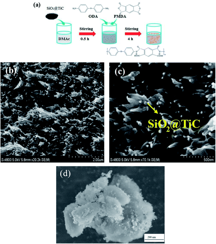
As shown in Fig. 1(a), the SiO2@TiC powder was dissolved in N,N-dimethylacetamide (DMAc) under ultrasonic stirring for 0.5 h. Subsequently, 4,4′-diaminodiphenyl ether (ODA) was added to the mixture at 25 °C, followed by an equimolar amount of pyromellitic dianhydride (PMDA), once the diamine had dissolved completely. A polyamic acid (PAA)/SiO2@TiC mixed solution was obtained by mechanical stirring for approximately 4 h. The mixed solution was coated on a glass sheet, which was used as the substrate for the composite film. Finally, the PAA/SiO2@TiC composite film was placed in an oven which was heated using the following temperature profile: 100 °C for 1 h, 200 °C for 1 h, and 280 °C for 1 h.14–19 The final PI/SiO2@TiC composite film was obtained after dehydration and cyclization. Four different PI/SiO2@TiC composite films were prepared by varying the weight percentage of the SiO2@TiC powder used (3, 5, 10, and 15 wt%). The 10 wt.%-SiO2@TiC-modified PI composite film was characterized by SEM and powder XRD techniques.Results and discussion
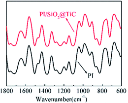
SEM was used to describe the micromorphology of fillers and composite films. The SEM images of the PI/SiO2@TiC composite film prepared using 10 wt% SiO2@TiC powder are shown in Fig. 1(b) and (c). The freeze-fractured cross-section of the PI/SiO2@TiC composite film shows that the SiO2@TiC particles are dispersed homogeneously in the PI matrix, with no significant aggregation of the particles. Particles which was added into the polymer matrix integrated well with the polyimide. The particles exhibit a microballoon-like morphology, indicating that TEOS was successfully hydrolyzed into microspheres of SiO2. From the images, fillers were uniform and the mean grain size of the SiO2@TiC particles was about 200 nm. In addition, the TiC particles are covered with a layer of SiO2, which impedes the flow of electrons and lowers the dielectric loss effectively. Fig. 1(d) showed the morphology features of the SiO2@TiC fillers. SiO2 as a coat covered the TiC's surface. It can be seen from the picture that the size from the hydrolyzation of TEOS is homogeneous and diminutive.Fourier transform infrared spectroscopy (FT-IR) analysis was performed to elucidate the effect of the structure of the composites on their properties. The FT-IR spectra of the PI/SiO2@TiC (10 wt%) composite and pure PI are shown in Fig. 2. In the case of pure PI, characteristic peaks related to the imide carbonyl asymmetrical and symmetrical stretches (C![[double bond, length as m-dash]](https://www.rsc.org/images/entities/char_e001.gif) O) are observed at 1715 cm−1 and 1776 cm−1. On the other hand, the peak at 1380 cm−1 corresponding to the stretching of the C–N bond and that at 720 cm−1 related to the imide ring are absent, in contrast to the case of the precursor. The disappearance of amide characteristic absorption peaks indicated a virtually complete conversion of diamine monomer into polyimide.20–23 Further, the similarity between the spectra of pure PI and PI/SiO2@TiC suggests that the addition of SiO2@TiC had no effect on the imidization of PI,24,25 so that the composite films can keep well flexibility.
O) are observed at 1715 cm−1 and 1776 cm−1. On the other hand, the peak at 1380 cm−1 corresponding to the stretching of the C–N bond and that at 720 cm−1 related to the imide ring are absent, in contrast to the case of the precursor. The disappearance of amide characteristic absorption peaks indicated a virtually complete conversion of diamine monomer into polyimide.20–23 Further, the similarity between the spectra of pure PI and PI/SiO2@TiC suggests that the addition of SiO2@TiC had no effect on the imidization of PI,24,25 so that the composite films can keep well flexibility.
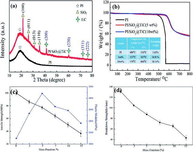
The XRD patterns of the unmodified PI film and the PI/SiO2@TiC composite film (10 wt%) are shown in Fig. 4(a). It was used to analyze the structure and component of the composite films. A very broad peak is observed in the low-angle region at a 2θ value of approximately 20°; this is the characteristic band of PI. In the spectrum of the PI/SiO2@TiC composite, additional peaks are observed at 21.873, 26.749, 31, and 36.265°; these are assigned to the (100), (011), (013), and (110) crystal planes, respectively, of SiO2 (PDF No. 47-0717). In addition, the peaks at 41.710, 60.517, 72.369, and 76.139° are related to the (200), (220), (311), and (222) crystal planes, respectively, of TiC (PDF No. 32-1383).26 These peaks proved the presences of SiO2 and TiC. SiO2 deriveded from the hydrolyzation to TEOS.
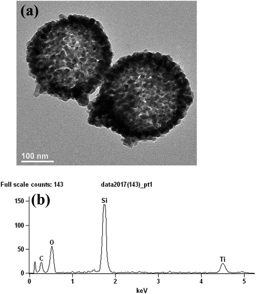
TEM and EDS can characterize the structure of the SiO2@TiC particle. As is shown in the Fig. 3(a), SiO2 was the shell of particle. TiC was the core of the particle. SiO2 was microspheric and attached to the surface of TiC. The auxiliary instructions of the structure is the Fig. 3(b)—EDS of the particle. Fig. 3(b) shows that the particle was composed of Ti, C, Si and O.
The thermal stabilities of the PI/SiO2@TiC composite films were investigated by thermogravimetric analysis (TGA). The TGA curves of the pure PI film and the PI/SiO2@TiC composite films in Fig. 4(b) indicated clearly that the thermal stabilities of the composite films are significantly higher than that of the pure PI film. The 5% and 10% weight loss temperatures of both the 5 wt% PI/SiO2@TiC and the 10 wt% PI/SiO2@TiC films were higher than those of the PI film. This is attributed to the addition of SiO2, which has a high thermal stability. In addition, the higher residual weights of the PI/SiO2@TiC composite films than that of the pure PI film are due to the presence of SiO2, which is beneficial as an inorganic filler to improve the thermal stability of composite materials.27,28 The melting point for SiO2 is 1650 °C, and for TiC is 3140 °C, the core–shell structure could improve thermal decomposition temperature of the films. In addition, the large specific surface area of the composite, because of the good dispersion of the filler in the matrix, effectively hinders the escape of small molecules.
Fig. 4(c) shows the tensile strengths and the elastic moduli of the PI/SiO2@TiC composites. The elastic modulus of the composite film first increases and then decreases with an increase in the mass fraction of SiO2@TiC. When a small amount of the rigid SiO2 particles is added to the PI matrix, the elastic modulus increases; however, when the SiO2 content is increased beyond a certain limit, the particles aggregate and cause defects between the inorganic and the organic phases, leading to a decrease in the tensile strength of the composite and its eventual breakage. The breakdown strengths of the various PI/SiO2@TiC composites are shown in Fig. 4(d). The introduction of the SiO2@TiC powder creates numerous charge-concentration points in the polymer, leading to the accumulation of charges and its partial discharge. The surfaces of the SiO2@TiC particles have high activity owing to the presence of electron vacancies and other active sites, which tend to absorb a large number of carriers to maintain their energy level balance. As these carriers accumulate, channels for partial discharge are formed, which eventually destroy the polymer matrix and cause breakdown of the material.29,30
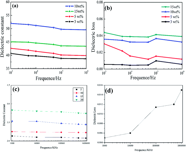
The frequency dependence of the dielectric constants of pure PI and the PI/SiO2@TiC composites is displayed in Fig. 5(a). The dielectric constant of a material can be calculated using the following equation.
The capacitances (Cp) of the composite films were measured using an LCR digital electric bridge, while the thicknesses of the films (d) were measured using a thickness gauge. Furthermore, A is the testing area of the sample and ε0 is the dielectric constant of vacuum (ε0 = 8.85 × 10¹² F m−1).31 When the mass fraction of the SiO2@TiC powder is 10%, the dielectric constant of the corresponding PI/SiO2@TiC composite film is 52 (103 Hz), its dielectric loss is 0.036. For the dielectric constant of SiO2 is 3, the dielectric constant of SiO2@TiC/PI is much higher than the dielectric constant of SiO2/PI composites which is showed in the Fig. 5(c) is 3–4. TiC as the conductive filler, the addition could increase the dielectric constant by a wide margin. As is shown in the Fig. 6(a), the dielectric constant of TiC/PI could increase to 142 when the mass fraction is 15%. The breakdown strength of PI/SiO2@TiC is 103.6 kV mm−1. The dielectric constant of pure PI film is 3.8–4.0 (1000 Hz). The dielectric constant of the composite film had improved significantly. For all the samples, the dielectric constant (εr) decreases with an increase in the frequency, because the dielectric constant of the filler is different from that of the PI film and is affected by the polarization of the PI/SiO2@TiC interface.10
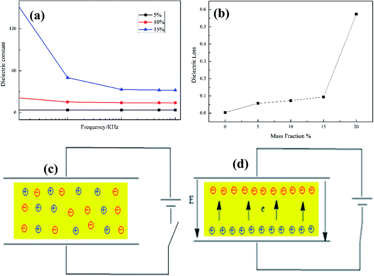 | ||
| Fig. 6 (a) Dielectric constants and (b) dielectric loss of SiO2/PI composites as functions of the measurement frequency, (c) and (d) models of interfacial polarization. | ||
The frequency dependence of the dielectric loss values of the PI/SiO2@TiC composites is shown in Fig. 5(b). When the test frequency is low (less than 10 kHz), the dielectric loss increases slowly, because dielectric polarization occurs in the low-frequency electric field and the dipole readily adjusts to the changes in the electric field. However, when the frequency of the alternating electric field is high, the dipole is affected by the frictional resistance arising from the internal viscous effects of the medium. Thus, the dipole is unable to adjust quickly to the change in the electric field, and the dielectric loss increases.
Fig. 5(d) and Fig. 6(b) referred to the dielectric loss of TiC/PI and SiO2/PI composites. Though the dielectric constant of TiC/PI is highest, the dielectric loss exceeded others a lot.
The PI/SiO2@TiC interface within the composite film has a large number of defects,33,34 such as hanging bonds, vacancy groups, and voids, which cause charge distribution at the interface. Under the force of an electric field, the positive and the negative charges move toward their respective poles, and the result is an aggregation of charges at the interface defects. This leads to the formation of an interfacial double layer—this phenomenon is also called interfacial charge polarization. The models of interfacial polarization, shown in Fig. 6(c) and (d), suggest that this phenomenon is responsible for the increased dielectric constants of the composite films.32
Conclusions
PI-based composite films doped with SiO2@TiC particles were fabricated by in situ dispersive polymerization. The results showed that TEOS was hydrolyzed into microspheres, which were coated on the TiC surface. The dielectric constant of the PI/SiO2@TiC (10 wt%) composite film increased from 3.8 to 52 with the addition of the high-dielectric-constant SiO2@TiC particles, while its dielectric loss and breakdown strength were 0.036 and 103.6 kV mm−1, respectively. The TGA results indicated that the thermal stability of the composites was significantly higher than that of pure PI. Thus, the results of the present study confirm that the addition of modified TiC to PI effectively improves its dielectric constant. To establish the principles to design and prepare polymer-based composites with high dielectric constant and low dielectric loss, the effects of functional fillers and the interaction on the dielectric properties of the composites. In this paper, the particle SiO2@TiC enhanced the dielectric constant of the composites, the adding of SiO2@TiC keep the dielectric loss remains in a very low level.Conflicts of interest
There are no conflicts to declare.References
- Y. Feng, C. H. Wang and S. X. Liu, Mater. Lett., 2016, 185, 491 CrossRef CAS.
- J. Yu, T. Zhang, L. Xu and P. Huang, Chin. J. Chem., 2017, 35, 1586 CrossRef CAS.
- H. Wang, D. Zhu, W. Zhou and F. Luo, J. Alloys Compd., 2015, 648, 313–319 CrossRef CAS.
- X. Li, G. Wang, L. Huang, X. Kang, F. Cheng, W. Zhao and H. Li, Mater. Lett., 2015, 148, 22 CrossRef CAS.
- X. Peng, Q. Wu, S. Jiang, M. Hanif, S. Chen and H. Hou, Mater. Lett., 2014, 133, 240 CrossRef CAS.
- S. Kou, S. Yu, R. Sun and C. Wong, IEEE, 2013, 86, 7 Search PubMed.
- M. W. Cole, E. Ngo and C. Hubbard, J. Appl. Phys., 2013, 114(16), 1323–1328 CrossRef.
- L. Liu, Y. Zhang, F. Lv, W. Tong, L. Ding, K. Paul and P. Chu Li, RSC Adv., 2016, 90, 86817 RSC.
- L. Z. Liu, X. H. Gao, L. Weng, H. Shi and C. Wang, IEEE, 2012, 10, 67–70 Search PubMed.
- X. D. Lv, N. Lv, J. F. Gao, J. Xu. and C. L. Lv, Adv. Mater. Res., 2007, 56, 601 Search PubMed.
- Y. He, C. Y. Tong, L. Geng, L. D. Liu and C. L. Lu, J. Membr. Sci., 2014, 458, 36 CrossRef CAS.
- Y. Yuan, B. P. Lin, X. Q. Zhang, L. W. Wu and Y. Zhan, Appl. Polym. Sci., 2008, 110, 1515 CrossRef CAS.
- B. K. Zhu, S. H. Xie, Y. X. You and X. Z. Kang, J. Funct. Biomater., 2005, 59, 2403 Search PubMed.
- X. Fang, X. Liu, Z. K. Cui, J. Qian, J. Pan, X. Li and Q. Zhuang, J. Mater. Chem. A, 2015, 3, 10005 CAS.
- Y. Y. Yu, A. H. Jiang and W. Y. Lee, Nanoscale Res. Lett., 2016, 11, 488 CrossRef PubMed.
- C. Y. Ho, C. C. Chang and J. Y. Lee, J. Appl. Polym. Sci., 2010, 117, 3454 CAS.
- L. Tan, S. Liu, F. Zeng, S. Zhang, J. Zhao and Y. Yu, Adv. Technol., 2011, 22, 209 CrossRef CAS.
- C. Hamciuc, E. Hamciuc, M. Olariub and R. Ciobanub, Polym. Int., 2010, 59, 668 CAS.
- J. H. Kang, C. E. Park and Y. H. Jeong, Europhys. Lett., 2007, 74, 903 CrossRef.
- Y. Huang, X. Huang, L. S. Schadler, J. He and P. Jiang, ACS Appl. Mater. Interfaces, 2016, 8, 25496 CAS.
- C. Liu, X. Pei, X. Huang, C. Wei and X. Sun, Chin. J. Chem., 2015, 33(2), 277 CrossRef CAS.
- D. H. Lee, J. H. Lee, D. W. Kim, B. K. Kim and H. J. Je, J. Ceram. Soc. Jpn., 2010, 118, 62 CrossRef CAS.
- R. Janssen, A. A. Gusev, T. A. Tervoort and C. Bastiaansen, Phys. Rev. A, 1999, 2, 2388 Search PubMed.
- H. X. Hu, Z. A. Hu, X. Y. Ren, Y. Y. Yang, R. B. Qiang, N. An and H. Y. Wu, Chin. J. Chem., 2015, 33, 199 CrossRef CAS.
- S. P. Lim, N. M. Huang and H. N. Lim, Ceram. Int., 2013, 39, 6647 CrossRef CAS.
- C. Zheng, X. F. Zhou, H. L. Cao, G. H. Wang and Z. P. Liu, Power Sources, 2014, 258, 290 CrossRef CAS.
- F. Y. Zeng, Y. F. Kuang, N. S. Zhang, Z. Y. Huang, Y. Pan, Z. H. Hou, H. H. Zhou, C. L. Yan and O. G. Schmidt, Power Sources, 2014, 247, 396 CrossRef CAS.
- X. J. Lu, H. Dou, B. Gao, C. Z. Yuan, S. D. Yang, L. Hao, L. F. Shen and X. G. Zhang, Electrochim. Acta, 2011, 56, 5115 CrossRef CAS.
- C. Kim, Y. O. Choi, W. J. Lee and K. S. Yang, Electrochim. Acta, 2004, 50, 883 CrossRef CAS.
- Z. P. Zhou and X. F. Wu, Power Sources, 2013, 222, 410 CrossRef CAS.
- M. Narkis, G. Lidor, A. Vaxman and L. Zuri, Polym. Int., 1999, 47, 201 CAS.
- X. D. Lv, N. Lv, J. F. Gao, J. Xu . and C. L. Lv, Polym. Int., 2007, 56, 601 CrossRef.
- Y. He, C. Y. Tong, L. Geng, L. D. Liu and C. L. Lu, J. Membr. Sci., 2014, 458, 36 CrossRef CAS.
- T. G. Kim, J. G. Lee, C. W. Park, H. S. Jo, M. Kim, M. Hest, D. Cho, Y. Chung and S. Yoon, J. Alloys Compd., 2018, 739, 653–659 CrossRef CAS.
| This journal is © The Royal Society of Chemistry 2018 |

