 Open Access Article
Effect of cobalt addition on the corrosion behavior of near equiatomic NiTi shape memory alloy in normal saline solution: electrochemical and XPS studies†
Nawal D. Alqarnia,
Joanna Wysocka b,
Nader El-Bagouryac,
Jacek Ryl
 b,
Mohammed A. Amin
 *ad and
Rabah Boukherroub
 e
e
aMaterials Science and Engineering Group, Department of Chemistry, Faculty of Science, Taif University, 888 Hawiya, Saudi Arabia. E-mail: maaismail@yahoo.com
bDepartment of Electrochemistry, Corrosion and Materials Engineering, Chemical Faculty, Gdansk University of Technology, Narutowicza 11/12, 80-233 Gdansk, Poland
cCentral Metallurgical Research and Development Institute (CMRDI), P. O. Box: 87 Helwan, Cairo, Egypt
dDepartment of Chemistry, Faculty of Science, Ain Shams University, 11566 Abbassia, Cairo, Egypt
eUniv. Lille, CNRS, Centrale Lille, ISEN, Univ. Valenciennes, UMR 8520 – IEMN, F-59000 Lille, France
First published on 24th May 2018
Abstract
The electrochemical and corrosion (uniform and localized) behavior of a binary Ni52Ti48 shape memory alloy (SMA) and two ternary Ni52Ti48−xCox (x = 1.5 and 4.0 wt%) SMAs were studied. Measurements were conducted in 0.9% NaCl solution at 37 °C employing various electrochemical methods. These include: linear polarization resistance (LPR), linear sweep voltammetry (LSV), chronoamperometry and dynamic electrochemical impedance spectroscopy (DEIS). Such measurements were complemented with scanning electron microscopy (SEM) and X-ray photoelectron spectroscopy (XPS) analysis. Results revealed that the addition of alloyed Co to NiTi significantly reduced the uniform corrosion rate of the studied SMA and greatly enhanced its pitting corrosion resistance. XPS measurements evidenced high stability of the passive layer and limited adsorption of chloride ions. Additionally, it was found that the passive layer remained primarily composed of titanium oxides. Microstructure changes accompanying the addition of Co were also used to account for its role in improving the corrosion resistance of these materials.
1. Introduction
Shape Memory Alloys (SMAs) represent a unique class of materials exhibiting peculiar properties like the shape memory effect, the superelasticity associated with damping capabilities, high corrosion and extraordinary fatigue resistance.1–5 Due to their potential use in an expanding variety of technological applications,6–9 an increasing interest in the study of the SMAs has been witnessed in the research community during the previous decades.SMAs are a distinguished category of shape memory materials with the ability to recover their shape when the temperature is increased even under high applied loads, resulting in high actuation energy densities. In addition, under specific conditions, SMAs can absorb and dissipate mechanical energy by undergoing a reversible hysteretic shape change when subjected to mechanical cyclic loading.10–14 These unique characteristics of SMAs have made them popular for sensing and actuation, impact absorption and vibration damping applications. SMAs do, however, exhibit low frequency response. Higher actuation frequencies are achievable for a class of SMAs called magnetic shape memory alloys, which have recently been investigated. The application of SMAs spans a wide variety of industrial sectors such as aerospace, automotive, biomedical, and oil exploration. Over the past few decades, several key works have explored the microstructural mechanisms, engineering effects, and applications of shape memory alloys.4,15,16
Two important sets of characteristics, namely biofunctionality and biocompatibility control the performance of any biomedical material.17,18 The former characteristic refers to the material ability to implement the required function, whereas the later determines material's compatibility with the body. For metallic biomaterials that are typically used in orthopedic implants, the functional requirements are high mechanical properties. These include yield strength, ductility, fatigue strength, and fracture toughness. The susceptibility of the material to corrosion and the effect the corrosion has on the tissue are the central aspects of biocompatibility.17,18
Shape memory alloys (SMAs), particularly NiTi SMA, have provided new insights into biomedical area for cardiovascular, orthopedic and dental applications, and for making advanced surgical instruments, as they meet the requirements for orthopedic implantation, namely high biofunctionality and superior biocompatibility. Therefore, it is worth to highlight the orthopedic applications of this material.19,20 In this regard, literature revealed numerous articles dealing with corrosion behavior of NiTi SMAs in various physiological environments.21–23 For instance, Khalil-Allafi et al.24 investigated the corrosion behavior of Ni50.7Ti49.3 SMA in two physiological environments, namely Ringer and NaCl (0.9%) solutions. Their topographical investigations demonstrated that the corrosion products are nearly same in the two solutions, even though the breakdown potential of the tested SMA in NaCl 0.9% solution was nobler than that measured in Ringer solution, revealing higher corrosion resistance, and hence lower toxicity, in the former solution.
Figueira et al.25 studied the corrosion behavior of NiTi alloy (Ni 50.2 at%–Ti) in Hanks' solution at 37 °C, employing various electrochemical methods. They also considered other orthopedic implants, namely Ti–6Al–4V alloy and 316L stainless steel for comparison. It was found that the corrosion behavior of NiTi was almost similar to Ti than to Ni, as the chemical composition and protective characteristics of the passive oxide film formed on NiTi was similar to that formed on Ti. Based on these findings, the tested materials were ranked according to their corrosion resistance as: 316L stainless steel < NiTi < Ti–6Al–4V.25
Application of NiTi alloys in medical device is a result of their high corrosion resistance and biocompatibility in combination with increased modulus and high stiffness, as already highlighted.26 Furthermore, Fasching et al.27 investigated NiTi alloys containing 1–2% of cobalt and revealed that in comparison to NiTi alloys, NiTiCo has approximately 30% higher modulus, loading plateau and unloading plateau with similar biocompatibility and no reactivity in both investigated tests, namely: cytotoxicity and hemolysis. The yield strength improvement was also confirmed for NiTi alloys containing 2–10% Co addition.28 To some extent, these results can be explained with two-step transformation, since martensitic transformation temperature is induced by Co addition separating it from R phase transformation. Alloys containing up to 10% of cobalt were also studied for material removal rate, microstructure and hardness with wire electro discharge machining technique.29
In order for these alloys to be successfully used, the effect of cobalt on the corrosion resistance properties must be well defined. Huang et al.26 investigated the corrosion properties of these alloys in PBS solution, claiming similar behavior to cobalt-less NiTi alloys and no effect of galvanic corrosion within stent. These studies however were carried out in mild environment, where pitting or crevice corrosion is not to be expected.
Since Co-based alloys are generally much more resistant to localized corrosion effects, it is expected that sufficient Co additive into the alloy structure will increase its resistance to this form of damage, unless fretting or other mechanical damage occurs to the surface oxide.30 Recently, we have investigated the electrochemical and corrosion behavior of Co-based magnetic shape memory alloys (MSMAs) in 0.5 M NaCl to reveal significant corrosion resistance of the studied MSMAs, evidenced through electrochemical and XPS studies, together with SEM/EDX examinations.31
However, the number of papers published so far is insufficient to adequately cover the bio-corrosion behavior of NiTi SMAs, particularly ternary NiTi-based SMAs,32,33 and is not commensurate with the medical importance of these materials. In addition, literature revealed limited number of articles concerning the effect of Co addition on the corrosion behavior of NiTi SMAs.31,34 Thus, the objective of this work was to investigate the passivation influence of alloyed Co during the uniform and pitting corrosion processes of Ni52Ti48−xCox (x = 0, 1.5 and 4%) ternary SMAs in 0.9% NaCl solution at 37 °C using various electrochemical techniques, complemented with SEM/EDX and full XPS studies. The passivation impact of alloyed Co is translated into an obvious enhancement in the corrosion resistance of these materials.
2. Experimental
2.1. Materials
The working electrodes employed in this work were made of NiTiCo SMAs of chemical composition Ni52Ti48−xCox (x = 0, 1.5, and 4.0 Co at%). These alloys were fabricated by melting Ni, Ti and Co elements of purity higher than 99.99% in induction vacuum furnace, as fully described elsewhere.34 Rods of these alloys were used for electrochemical measurements. Such rods were mounted in a polyester resin leaving an exposed area of ∼0.2 cm2. Before each run, the working electrodes were wet ground using a silicon carbide paper (600-grit), washed in distilled water, and finally rinsed with absolute ethanol.2.2. Electrochemical setup and solutions
Electrochemical measurements were performed in a standard jacketed three-electrode cell, with a saturated calomel electrode (SCE) and a Pt mesh electrode serving respectively as reference electrode and auxiliary electrode. This standard electrochemical cell was linked to a PC-connected potentiostat/galvanostat AUTOLAB (PGSTAT30) to run and record the various electrochemical techniques employed in this work. Measurements were conducted in a normal saline solution, namely 0.9% NaCl, freshly prepared using water purified by a Millipore Milli-Q system (18.2 MΩ cm). The used salt was analytical grade purchased from Sigma-Aldrich. Solution temperature was maintained constant at (37 ± 0.2 °C) using a temperature-controlled water bath, FP40-MA Refrigerated/Heating Circulator, with its water being circulating through the outer cell jacket.2.3. Electrochemical measurements
The reproducibility was ensured via repeating each run at least three times. Arithmetic mean and standard deviation of the various electrochemical parameters were calculated and reported.
2.4. Surface characterizations
Prior to microscopic and spectroscopic investigations, the SMA samples undergone mechanical pretreatment by means of grinding (waterproof abrasive papers SiC 240, 600, 1200 and 2500) and polished (diamond suspension 6 and 1 μm, with a finish on 0.05 μm silica). Both of these processes were carried out using Digiprep 251 (Metkon, Turkey).Microstructural analysis was carried out using scanning electron microscopy (SEM), S-3400N (Hitachi, Japan) with a tungsten electron source. Back-scatter electron (BSE) mode was utilized, operating at an accelerating voltage of 20 kV, for better contrast of metallic phases. The SEM images of polished surface of various investigated SMA alloys were analyzed using the program for data visualization and analysis (Gwyddion, 2.40, Czech Republic).35
X-ray photoelectron spectroscopy (XPS) was used for the evaluation of the long term exposure effect of the as-prepared Ni52Ti48−xCox alloys (x = 0, 1.5 and 4.0%). The measurements were performed for as-polished sample and after 7 days immersion in 0.9% NaCl solution at 37 °C. After this treatment, the samples were cleaned in deionized water (2× 10 min) and dried. No other treatment was implemented in order not to compromise the subtle chemical changes on the surface. Analysis was performed for titanium, nickel, cobalt, chlorine and oxygen.
3. Results and discussion
3.1. Uniform corrosion studies
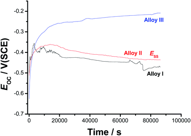 | ||
| Fig. 1 Open-circuit potential (EOC) vs. time (up to 24 h) responses of the three tested SMAs recorded in 0.9% NaCl solutions at 37 °C. | ||
For all tested alloys, within the first moments of immersion, EOC shifts towards nobler values, denoting passivation. This passivation behavior is most probably due to the high reactivity of the alloying elements (Ni, Ti, and Co), which induced an initial formation and growth of a passive oxide film. After its initial rise, EOC decays, referring to depassivation (oxide thinning/dissolution) induced by Cl− anions in solution, to a reasonably steady value (Ess). This behaviour indicates the occurrence of two opposite processes (passivation and destabilization of the passive layer) competing each other. The former, when predominates, impedes Cl− adsorption and oxide dissolution is subsequently delayed, drifting EOC to nobler values. The later process (passivity destabilization as a result of the aggressive attack of Cl− anions) activates the alloy surface thus, dragging EOC back toward active values. The competition between these two counter-acting processes may explain the appearance of potential fluctuations and a hump in the EOC – t curves of Alloy I and Alloy II, respectively. The ennoblement of both the hump's height and Ess upon the addition of alloyed Co may refer to improved passivation. These findings demonstrate, under these experimental conditions, that the addition of 1.5% alloyed Co to Alloy I can improve its corrosion resistance, but not enough to ensure efficient passivation. Further increase in the Co content (up to 4 at% in this study, Alloy III) has resulted in an efficient passivation during the period of that operation (24 h); the passivation of Alloy III continues till the end of the operation, where Ess is attained.
In spite of its tendency to passivate in these solutions, passivity of the Co-free SMA (i.e., Alloy I) turns to be weak and unstable compared with that of Alloy II and Alloy III, as indicated by current oscillations and the obvious decay in EOC till Ess. Its Ess value is always more negative than those measured for Alloys II and III. This means that the surface of Alloy I is more susceptible to corrosion in 0.9% NaCl than the surfaces of Alloys II and III. These results highlight the influence of the alloyed Co on the sample passivation.
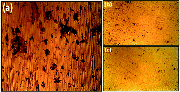
After 7 days of free corrosion in 0.9% NaCl solution at 37 °C, optical microscopy examination (Fig. 2) revealed that, in all cases, the corrosion pits (formed as a result of the aggressive attack of Cl− anions) are surrounded on all sides by regions covered with a protective oxide layer (passivity). Obviously, in presence of the alloyed Co, areas of passivity significantly increase at the expense of those of pits. This means that the pit area density (i.e., the ratio of pit area to total surface area) diminishes with alloyed Co content, suggesting better passivation impact of the alloyed Co and subsequent increase in the corrosion resistance.
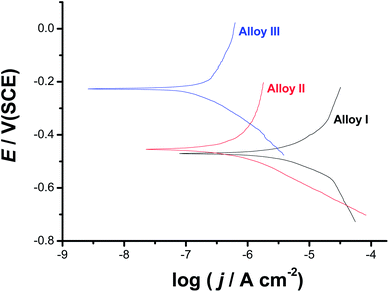 | ||
| Fig. 3 Cathodic and anodic polarization curves recorded for the three tested SMAs in 0.9% NaCl solution at a scan rate of 1.0 mV s−1 at 37 °C. | ||
The obvious decrease in jcorr with increase in Co content is a strong evidence for the influence of alloyed Co on the surface passivation. This is clear from Table 1, where Alloy III (the SMA with the highest content of alloyed Co, 4.0 at%) recorded the least jcorr value (0.26 μA cm−2) among the other tested alloys (jcorr: 14.1 and 0.62 μA cm−2 for Alloy I and Alloy II, respectively). In addition, the corrosion potential (Ecorr) drifts towards nobler values with increase in Co content, confirming passivation induced by alloyed Co. In order to gain more insight on the passivation influence of alloyed Co, polarization curves shown in Fig. 3 were analyzed using Tafel extrapolation method (ESI, Fig. S1†). The obtained data are listed in Table 1. A clear curvature, due to passivation induced by the alloyed Co, can be seen over the complete applied potential range of the anodic polarization curves, making calculation of the anodic Tafel slopes inaccurate.38–42 Therefore, McCafferty approach was applied here in order to estimate the anodic Tafel line under passivation conditions, see ESI† file for details (Section I).37 The high values recorded for βa (380–716 mV dec−1), which refer to delay in the rate of alloy dissolution due to passivation, may also be considered as another evidence for the influence of the alloyed Co on the surface passivation.
| Tested alloy | Tafel extrapolation | LPR | ||
|---|---|---|---|---|
| Ecorr/mV(SCE) | jcorr/μA cm−2 | Rp/Ω cm2 | jcorr/μA cm−2 | |
| Alloy I (0.0% Co) | −470(6) | 14.1(0.2) | 8954.2(35) | 13.4(0.2) |
| Alloy II (1.5% Co) | −455(4) | 0.62(0.1) | 52![[thin space (1/6-em)]](https://www.rsc.org/images/entities/char_2009.gif) 129.2(125) 129.2(125) |
0.75(0.14) |
| Alloy III (4.0% Co) | −227(3) | 0.26(0.05) | 203325(227) | 0.33(0.08) |
Linear polarization resistance (LPR) measurements were also performed to gain more insight on the influence of alloyed Co on the uniform corrosion behavior of the tested SMAs. Such measurements were carried out in 0.9% NaCl solution at 37 °C. The potential was scanned around Ecorr (E = Ecorr ± 20 mV) at a scan rate of 0.2 mV s−1 (Fig. 4). Polarization resistance (Rp = (dE/dj)E=Ecorr) values derived from the slopes of the LPR plots were inserted in the Stern–Geary equation43 for accurate evaluation of jcorr.
| jcorr = B/Rp = {βaβc/2.303 (βa + βc)}/Rp | (1) |
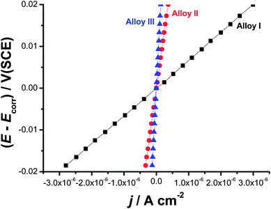 | ||
| Fig. 4 Linear polarization resistance plots measured for the three tested SMAs in 0.9% NaCl solution at a scan rate of 0.2 mV s−1 at 37 °C. | ||
As can be seen, there is a good agreement between jcorr values obtained from the two polarization methods, namely Tafel extrapolation and LPR (Table 1). Thus, LPR method confirms the validity of Tafel extrapolation method in evaluating the uniform corrosion rates (expressed here as jcorr values).44 Here again, Alloy III recorded the highest Rp value (203![[thin space (1/6-em)]](https://www.rsc.org/images/entities/char_2009.gif) 325 Ω cm2), and hence exhibits the highest corrosion resistance, among the tested alloys. This Rp value of Alloy III is 34 and 7 times greater than those measured for Alloy I (8954 Ω cm2), and Alloy II (52
325 Ω cm2), and hence exhibits the highest corrosion resistance, among the tested alloys. This Rp value of Alloy III is 34 and 7 times greater than those measured for Alloy I (8954 Ω cm2), and Alloy II (52![[thin space (1/6-em)]](https://www.rsc.org/images/entities/char_2009.gif) 129 Ω cm2), respectively.
129 Ω cm2), respectively.
 | ||
| Fig. 5 Nyquist impedance plots vs. exposure time for each investigated SMA alloy in 0.9% NaCl under 37 °C. | ||
To fully address the changes of electric parameters of investigated samples and in particular the behavior of the passive layer, data should be analyzed with electric equivalent circuit (EEC). The structure of TiO2 passive layer is composed of the inner, barrier layer and outer, porous layer of low resistivity.44,45 For this reason, two time-constant electric equivalent circuits (EEC) are often used for fitting of impedance data.46,47 However, due to the porous nature of the outer layer both of the time constants overlap on the impedance spectra, revealing capacitance dispersion. In these cases, the constant phase element (CPE) is often used, as it is capable to appropriately express normal time constant distribution from both the outer and the inner layer. CPE takes into account dispersion of capacitance behaviour, which originates from multiple factors, such as multiple layers, adsorption and diffusion processes, surface geometry and presence of intermetallic phases.48–50 This type of model simplification is often used during impedance monitoring in order to obtain continuous trend of changes over time of exposure, which is required for proper representation of investigated system.51–53 The effective capacitance can be further estimated on the base of CPE using estimation proposed by Hirschorn et al.54,55
While authors tested numerous EEC's, the best trend of changes together with the best fit (measured as Chi2 parameter) was observed for R(QR) circuit (ESI, Fig. S3(d)†). Following equivalent circuit is commonly found to describe NiTi alloys exposed to electrolyte containing chloride ions.56–60 Rsol stands for electrolyte resistance and Rct for charge transfer resistance through metal/electrolyte interface. Constant phase element (CPE) represents the capacitance of both the inner and the outer passive layer, while the smallest capacitance dominates CPE value. Admittance of CPE is given by equation 1/Z = QCPE(jω)n. It is worth noting that for n = 1, CPE describes a capacitor. The key contributing component is the breakdown of passive layer and initiation of pitting corrosion, leading to surface heterogeneities of the electrode properties. In the case of NiTi alloys, the passive layer consists mainly of titanium oxides, which has been confirmed by XPS analysis (see later).
Fig. S3(a), ESI,† displays the changes of quasi-capacitance Q with time of exposure in NaCl solution. The behavior is similar for each investigated alloy. Initially Q decreases and after 2–3 days it remains constant throughout the rest of experiment. Since the capacitance value is in reverse proportion to layer thickness, results prove the formation and stabilization of the passive layer. Fig. S3(c), ESI,† exhibits the charge transfer resistance changes during the experiment. It is important to state that each investigated alloy was characterized by very high value of this parameter, ranging from 0.5 up to even 10 MΩ cm2. The highest increase of Rct was observed for Alloy III, typically occurring after day 3. This effect corroborates with TiO2 passive layer formation and testifies increase of corrosion resistance of investigated alloys.61 On the other hand, gradual decrease of Rct for Alloy I might correspond to deterioration of its protective properties and presence of pitting corrosion, as confirmed by other studies (SEM and XPS). Similar behavior was observed for other metals under pitting corrosion conditions.61,62
3.2. Anodic behavior (kinetics of passive layer growth and its breakdown)
Fig. 6 exhibits the potentiodynamic anodic polarization curves recorded for the studied alloys in 0.9% NaCl solution at a scan rate of 1.0 mV s−1 at 37 °C. Obviously, there is no active dissolution near the corrosion potential (Ecorr), as the studied alloys tend to passivate in such solutions (revisit Fig. 1). Passivity of these materials was also evidenced from XPS analysis (see later). Passivity of Alloys II and III persists over a wide range of potential. It extends with a very low passive current (jpass) up to the pitting potential, Epit. Alloy I's passivity seems much weaker than that of Alloys II and III, as its jpass is higher and enhances with potential (clearly seen the inset of Fig. 6). Once Epit is reached, remarkable changes in the passive region have occurred. The passive current increased steadily with no sign for oxygen evolution, denoting passivity breakdown and initiation of pitting attack caused by Cl− anions. Once initiated, pits are stabilized by the delocalized development of severe conditions originated from metal cation hydrolysis and migration of the aggressive Cl− anions.63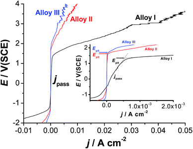 | ||
| Fig. 6 Linear polarization curves recorded for the three tested SMAs in 0.9% NaCl solution at a scan rate of 1.0 mV s−1 at 37 °C. | ||
The lower jpass values of Alloys II and III, in addition to the remarkable positive (noble) shift in their Epit values which resulted in an obvious increase in the pitting corrosion resistance Rpit, Rpit = |Ecorr − Epit|63 as compared with Alloy I, confirm uniform corrosion studies (revisit Section 3.1), and adds another evidence for the passivation influence of alloyed Co.
Chronoamperometry (current (j)/time (t) transients) measurements were also recorded to gain more insight on the effect of Co addition on the kinetics of passive layer growth and passivity breakdown (Fig. 7). Measurements were recorded in 0.9% NaCl solutions at 37 °C at two applied anodic potentials, Ea, namely 0.5 and 1.5 V vs. SCE. The location of the former Ea value, namely 0.5 V vs. SCE is far below the Epit value of any of the studied alloys, while that of the later (1.5 V vs. SCE) is beyond (Epit)Alloy I (1.25 V vs. SCE) and very close to (Epit)Alloy II (1.65 V vs. SCE) and (Epit)Alloy III (1.75 V vs. SCE), clearly seen in the inset of Fig. 6. The features vary according to the location of Ea with respect to Epit and the chemical composition of the studied alloy.
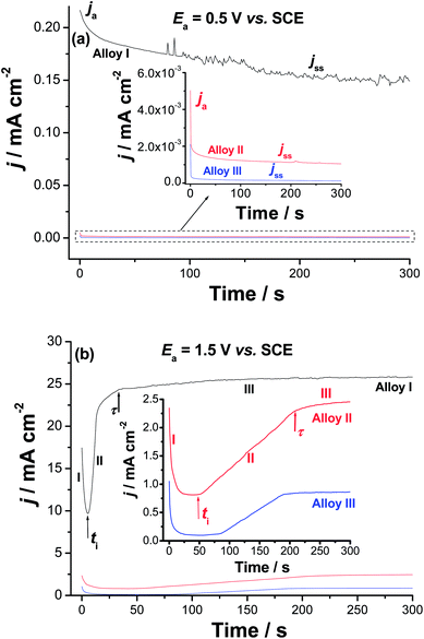 | ||
| Fig. 7 Chronoamperometry (current vs. time) measurements recorded for the studied alloys in 0.9% NaCl solution at 37 °C at (a) Ea = 0.5 V vs. SCE and (b) Ea = 1.5 V vs. SCE. | ||
When Ea is far from Epit (Fig. 7a), for all samples, the j/t curves exhibit two stages for the passive layer growth. The anodic current (ja) decreases with time during the first stage, denoting passive layer formation and growth. This decay in current is followed by a steady-state, the current passing through the passive film, jss (or jpass), referring to a passive film of constant thickness. This constancy of the passive film thickness is most probably due to a balance between the rates of the passive layer growth and dissolution. The balance between such two counter-acting processes makes the oxide film hardly grows.63–65
On the other hand, as Ea approaches Epit, the three studied alloys exhibit j–t curves with three distinct stages (Fig. 7b). The first stage is the passivation stage, as its current falls with time. The second stage involves passivity breakdown and subsequent pit formation and growth. Stage II started when the current of the first stage reached its minimum value. This has occurred at a certain time called the incubation time (ti); the time the aggressive Cl− anions need to remove the passive film locally and reach the base metal.66–70 The current associated with this stage is termed as the pit growth current, jpit. Stage II ends at another time (τ), denoting the onset of the last steady-state stage (stage III), during which the products of the pitting corrosion process are expected to precipitate inside the pits thus, hindering current flow through such blocked pits. In the same time, the current tends to grow as a result of metal dissolution due to pitting. Steady-state of the last stage is attained when the current rise due to metal dissolution (pit formation) is balanced by current decay caused by pitting corrosion products' blockade of the formed pits.
It follows from Fig. 7 that the rate of ja decay (i.e., rate of passivation) of Alloys II and III (see the inset of Fig. 7a) is much higher than that of Alloy I. In addition, jss diminishes significantly from Alloy I to Alloys II and III. The lower passivation rate and higher jss values of Alloy I, together with the obvious oscillations in its jss (see Fig. 7a) are strong evidences for its weak passivity compared with Alloys II and III. The weak passivity of Alloy I compared to Alloys II and III is also evident from Fig. 7b. This is clear from its shorter ti and higher jpit values (i.e., higher susceptibility toward pitting corrosion) as compared with those measured for Alloys II and III. Thus, Alloys II and III tend to passivate in these solutions much more effectively than Alloy I. These results provide another proof for the passivation impact of alloyed Co, which strengthens alloy's passivity making it more resistant to passivity breakdown and subsequent pitting attack.
3.3. Role of alloyed Co
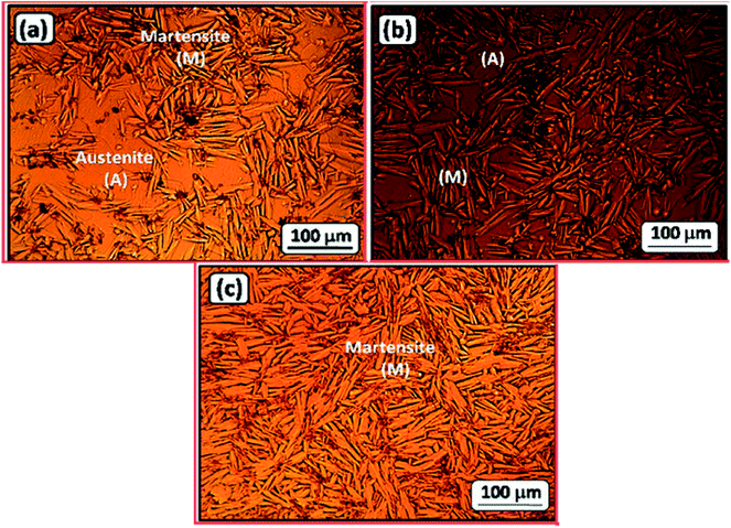
To further assess the effect of alloyed Co on the microstructure of the NiTi SMA, the samples were polished and imaged by SEM (Fig. S5, ESI†). These images have further undergone processing using Gwyddion software for evaluation of the average grain size and coverage of the Ti2Ni phase, here colored red. The results of these analyses (ESI, Fig. S6†) revealed that the grain size of Ti2Ni particles and Vf decrease with increasing Co content. These findings are in accordance with the previous results reported by El-Bagoury.71–73 Furthermore, the TiNi–1.5%Co sample (Alloy II) shows an unexpected pattern of intermetallic phase (supposedly Ti2Ni), that is longitudinal, thin and often appears to be curled. More insight into the microstructure of this sample is discussed in Fig. S7 (ESI†).
The multi-phase microstructure of the studied alloys helps to form micro-galvanic cells, and hence favors corrosion. Such galvanic cells are expected to form between Ti2Ni precipitates, which function as anodes, and the other phases serving as cathodes. The variation in the chemical composition among the different phases in the microstructure may explain the obvious variation of the rates of corrosion of the studied SMAs. The presence of Co as an alloying element in such alloys decreased, as evidenced from the above electrochemical measurements, their rates of corrosion proportionally to its amount included in the alloy's matrix.
The obvious increase in the percentage of surface covered by the matrix (the passive region), (ESI, Fig. S8†), at the expense of the average grain area of the Ti2Ni intermetallic phase (anodic regions, the corroded areas), with Co content may account for the improved corrosion resistance of the Co-containing NiTi alloys (Alloys II and III). Another important reason behind the increased corrosion resistance of these alloys with increasing the Co content is the passivation influence of the alloyed Co. XPS examinations were performed to confirm the passivation impact of alloyed Co, vide infra.
| Tim | TiO2 | Ti2O3 | Nim | Ni(OH)2 | Com | Co3O4 | Cl | O | |
|---|---|---|---|---|---|---|---|---|---|
| BE [eV] | 454.2 | 458.6 | 455.5 | 852.7 | 856.0 | 777.9 | 779.9 | 198.3 | 530.1 |
| As-polished | |||||||||
| Alloy I | 10.1 | 16.6 | 8.4 | 19.3 | 7.4 | — | — | — | 38.2 |
| Alloy II | 10.0 | 15.1 | 7.0 | 18.5 | 5.9 | 4.3 | 1.2 | — | 38.0 |
| Alloy III | 10.1 | 16.3 | 7.3 | 19.4 | 6.2 | 3.7 | 1.0 | — | 36.0 |
![[thin space (1/6-em)]](https://www.rsc.org/images/entities/char_2009.gif) |
|||||||||
| After exposure | |||||||||
| Alloy I | 3.7 | 24.6 | 2.6 | 4.5 | 2.8 | — | — | 2.5 | 59.3 |
| Alloy II | 2.8 | 25.4 | 2.2 | 4.4 | 1.7 | — | 0.9 | 1.2 | 61.4 |
| Alloy III | 6.5 | 25.0 | 1.9 | 2.8 | 1.7 | — | 1.2 | — | 60.9 |
| O-Me | OH/CO | H2O | Ratio | ||
|---|---|---|---|---|---|
| BE/eV | 529.8 | 531.1 | 533.1 | OH![[thin space (1/6-em)]](https://www.rsc.org/images/entities/char_2009.gif) : :![[thin space (1/6-em)]](https://www.rsc.org/images/entities/char_2009.gif) O2− O2− |
H2O![[thin space (1/6-em)]](https://www.rsc.org/images/entities/char_2009.gif) : :![[thin space (1/6-em)]](https://www.rsc.org/images/entities/char_2009.gif) OH OH |
| As-polished | |||||
| Alloy I | 13.2 | 67.3 | 19.5 | 5.1![[thin space (1/6-em)]](https://www.rsc.org/images/entities/char_2009.gif) : :![[thin space (1/6-em)]](https://www.rsc.org/images/entities/char_2009.gif) 1 1 |
0.29![[thin space (1/6-em)]](https://www.rsc.org/images/entities/char_2009.gif) : :![[thin space (1/6-em)]](https://www.rsc.org/images/entities/char_2009.gif) 1 1 |
| Alloy II | 18.3 | 72.4 | 9.3 | 4.0![[thin space (1/6-em)]](https://www.rsc.org/images/entities/char_2009.gif) : :![[thin space (1/6-em)]](https://www.rsc.org/images/entities/char_2009.gif) 1 1 |
0.13![[thin space (1/6-em)]](https://www.rsc.org/images/entities/char_2009.gif) : :![[thin space (1/6-em)]](https://www.rsc.org/images/entities/char_2009.gif) 1 1 |
| Alloy III | 19.8 | 69.8 | 10.4 | 3.5![[thin space (1/6-em)]](https://www.rsc.org/images/entities/char_2009.gif) : :![[thin space (1/6-em)]](https://www.rsc.org/images/entities/char_2009.gif) 1 1 |
0.15![[thin space (1/6-em)]](https://www.rsc.org/images/entities/char_2009.gif) : :![[thin space (1/6-em)]](https://www.rsc.org/images/entities/char_2009.gif) 1 1 |
![[thin space (1/6-em)]](https://www.rsc.org/images/entities/char_2009.gif) |
|||||
| After exposure | |||||
| Alloy I | 51.5 | 39.3 | 9.2 | 0.8![[thin space (1/6-em)]](https://www.rsc.org/images/entities/char_2009.gif) : :![[thin space (1/6-em)]](https://www.rsc.org/images/entities/char_2009.gif) 1 1 |
0.23![[thin space (1/6-em)]](https://www.rsc.org/images/entities/char_2009.gif) : :![[thin space (1/6-em)]](https://www.rsc.org/images/entities/char_2009.gif) 1 1 |
| Alloy II | 49.0 | 40.8 | 10.2 | 0.8![[thin space (1/6-em)]](https://www.rsc.org/images/entities/char_2009.gif) : :![[thin space (1/6-em)]](https://www.rsc.org/images/entities/char_2009.gif) 1 1 |
0.25![[thin space (1/6-em)]](https://www.rsc.org/images/entities/char_2009.gif) : :![[thin space (1/6-em)]](https://www.rsc.org/images/entities/char_2009.gif) 1 1 |
| Alloy III | 36.1 | 53.5 | 10.4 | 1.5![[thin space (1/6-em)]](https://www.rsc.org/images/entities/char_2009.gif) : :![[thin space (1/6-em)]](https://www.rsc.org/images/entities/char_2009.gif) 1 1 |
0.19![[thin space (1/6-em)]](https://www.rsc.org/images/entities/char_2009.gif) : :![[thin space (1/6-em)]](https://www.rsc.org/images/entities/char_2009.gif) 1 1 |
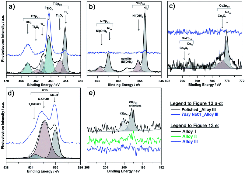
The chemical composition of the passive layer was similar for each investigated alloy prior to immersion in 0.9% NaCl aqueous solution. The presence of metallic component for each alloying element suggests low film thickness, not exceeding 12 nm, taking into consideration depth of XPS analysis. Both Ti and Ni spectra differ significantly as a result of immersion in NaCl solution. Primarily, the exposition influenced the passive state by formation of TiO2, and to a lesser extent Ti2O3. A decrease of the amount of metallic Ti and Ni suggests an increased passivation layer thickness, while amount of Com is on the level of the spectrometer threshold. Due to exposure and growth of the passive layer the cobalt peaks are barely distinguishable, even for Alloy III containing the highest Co content. It is important to note, that the surface of the passivated samples is mostly composed of titanium oxides, since the free energy for its formation is almost four times higher than that for nickel oxides.59 Similarly, the amount of cobalt is barely distinguishable suggesting its absence in the outer passive layer.
The explanation for better corrosion resistance of alloy with higher cobalt content (Alloy III) can be made based on the amount of detected chlorine in the form of chlorides. As can be seen on Fig. 9e and Table 3, the highest amount of chlorides (as high as 2.5 at%) was found for Alloy I (0% Co). These results corroborate with poor behavior of Alloy I under electrochemical examination and correspond well with theory of breakdown of the passive layer and initiation of pitting corrosion. On the other hand, the amount of chlorides for Alloy III (4% Co) was below the analysis threshold, proving much higher corrosion resistance. Furthermore, there is a significant pattern observable between contribution from Tim component and amount of alloyed Co. Alloy I has much lower Tim in analyzed spectra, which can be speculatively related to thicker, yet less compact passive layer. This conclusion corroborates with the information drawn on the base of changes in the chemistry of O1s spectra. It was revealed that for each investigated alloy, the as-polished sample is composed primarily of oxygen bound in hydroxyl groups (and oxygen due to air contamination), while as a result of the exposure to the corrosive medium (0.9% NaCl solution), the OH![[thin space (1/6-em)]](https://www.rsc.org/images/entities/char_2009.gif) :
:![[thin space (1/6-em)]](https://www.rsc.org/images/entities/char_2009.gif) Me-O ratio drops significantly indicating passivation, primarily in the form of TiO2. It should be noted that the chemistry of Alloy III is proved to be chemically stable and affected the least among investigated samples. At the same time, the passive film on the surface of Alloy III is to the smallest extent composed of chemisorbed water species, a feature characteristic for passive films possessing high corrosion resistance (see Table 3).79–82
Me-O ratio drops significantly indicating passivation, primarily in the form of TiO2. It should be noted that the chemistry of Alloy III is proved to be chemically stable and affected the least among investigated samples. At the same time, the passive film on the surface of Alloy III is to the smallest extent composed of chemisorbed water species, a feature characteristic for passive films possessing high corrosion resistance (see Table 3).79–82
3.4. SEM studies
The SEM images of SMA alloys after 7 days exposure in 0.9% NaCl at 37 °C are summarized in Fig. S9 (ESI†). These micrographs corroborate the results of both electrochemical and XPS studies about the positive influence of alloying cobalt on the corrosion resistance of SMAs. The lowest rate of failure has been recognized for Alloy III sample, where corrosion was only observed in the form of partial selective dissolution of anodic precipitates Ti2Ni. For Alloys I and II, much larger damage was observed, revealing initiation of corrosion failure on microstructure. Both size and number of corrosion pits are increasing with decreasing the cobalt content. Initiation of pitting corrosion by such micro-galvanic cells is often found in literature.56 Eventually, large pits of several hundred microns can be traced on the surface of Alloy I. The failure of material under exposure to chloride ions was further confirmed by XPS examination.4. Conclusion
Cobalt addition influences the microstructure of the tested SMAs through lowering the average size of Ti2Ni intermetallic phases as well as the overall area covered by these phases. It is highly possible, that one of the ways for cobalt to affect the corrosion resistance is through homogenization of surface electrochemical properties and decreased activity of micro-galvanic cells. The amount of chloride ions adsorbed onto the passive layer covering the investigated SMAs greatly diminishes with the addition of alloyed Co, thus proving the stability of the passive layer and explaining enhanced resistance to uniform and pitting corrosion processes. Nevertheless, the chemistry of passive layer does not dramatically change, being primarily composed of titanium oxide TiO2. The very high corrosion resistance of the investigated alloys was confirmed by impedance studies, where the charge transfer resistance through Co-enriched Alloy III sample was the highest and even improved during the exposition to corrosive environment.Conflicts of interest
There are no conflicts to declare.Acknowledgements
The authors acknowledge the financial aid received from Taif University, Saudi Arabia (Project Number 5486-438-1).References
- L. Kovarik, F. Yang, A. Garg, D. Diercks, M. Kaufman, R. D. Nobe and M. J. Mills, Acta Mater., 2010, 58, 4660–4673 CrossRef.
- S. U. Rehman, M. Khan, A. Nusair Khan, L. Ali, S. Zaman, M. Waseem and S. H. I. Jaffery, Mater. Sci. Eng., A, 2014, 619, 171–179 CrossRef.
- S. H. Hong, J. T. Kim, H. J. Park, Y. S. Kim, J. Y. Suh, Y. S. Na, K. R. Lim, C. H. Shim, J. M. Park and K. B. Kim, J. Alloys Compd., 2017, 692, 77–85 CrossRef.
- X. L. Meng, H. Li, W. Cai, S. J. Hao and L. S. Cui, Scr. Mater., 2015, 103, 30–33 CrossRef.
- D. Jiang, C. M. Landis and S. Kyriakides, Int. J. Solids Struct., 2016, 100–101, 41–53 CrossRef.
- C. Elibol and M. F. X. Wagner, Mater. Sci. Eng., A, 2015, 621, 76–81 CrossRef.
- A. N. Bucsek, G. A. Hudish, G. S. Bigelow, R. D. Noebe and A. P. Stebner, Shape Memory and Superelasticity, 2016, vol. 2, pp. 62–79 Search PubMed.
- O. Benafan, R. D. Noebe, S. A. Padulall, D. J. Gaydosh, B. A. Lerch, A. Garg, G. S. Bigelow, K. An and R. Vaidyanathan, Scr. Mater., 2013, 68, 571–574 CrossRef.
- N. A. Zarkevich and D. D. Johnson, Phys. Rev. Lett., 2014, 113, 265701 CrossRef PubMed.
- P. Chowdhury, L. Patriarca, G. Ren and H. Sehitoglu, Int. J. Plast., 2016, 81, 152–167 CrossRef.
- C. Chluba, W. Ge, R. Lima de Miranda, J. Strobel, L. Kienle, E. Quandt and M. Wutting, Science, 2015, 348, 1004–1007 CrossRef PubMed.
- P. Chowdhury and H. Sehitoglu, Fatigue Fract. Eng. Mater. Struct., 2016, 39, 652–674 CrossRef.
- P. Chowdhury, H. Sehitoglu and R. Rateick, Curr. Opin. Solid State Mater. Sci., 2016, 20, 140–150 CrossRef.
- R. Basu, M. Eskandari, L. Upadhayay, M. A. Mohtadi-Bonab and J. A. Szpunar, J. Alloys Compd., 2015, 645, 213–222 CrossRef.
- H. E. Karaca, E. Acar, G. S. Ded, S. M. Saghaian, B. Basaran, H. Tobe, M. Kok, H. J. Maier, R. D. Noebe and Y. I. Chumlyakov, Mater. Sci. Eng., A, 2015, 627, 82–94 CrossRef.
- M. Schmidt, J. Ullrich, A. Wieczorek, J. Frenzel, A. Schütze, G. Eggeler and S. Seelecke, Shape Memory and Superelasticity, 2015, 1, 132–141 CrossRef.
- I. Gotman, J. Endourol., 1997, 11, 383–389 CrossRef PubMed.
- M. Navarro, A. Michiardi, O. Castano and J. A. Planell, J. R. Soc., Interface, 2008, 5, 1137–1158 CrossRef PubMed.
- T. Sawaguchi, T. Maruyama, H. Otsuka, A. Kushibe, Y. Inoue and K. Tsuzaki, Mater. Trans., 2016, 57, 283–293 CrossRef.
- S. Alkan, P. Chowdhury, H. Sehitoglu, R. G. Rateick and H. J. Maier, Int. J. Fatigue, 2016, 84, 28–39 CrossRef.
- N. S. Manam, W. S. W. Harun, D. N. A. Shri, S. A. C. Ghani, T. Kurniawan, M. H. Ismail and M. H. I. Ibrahim, J. Alloys Compd., 2017, 701, 698–715 CrossRef.
- J. M. Jani, M. Leary, A. Subic and M. A. Gibson, Mater. Des., 2014, 56, 1078–1113 CrossRef.
- R. I. M. Asri, W. S. W. Harun, M. Samykano, N. A. C. Lah, S. A. C. Ghani, F. Tarlochan and M. R. Raza, Mater. Sci. Eng., C, 2017, 77, 1261–1274 CrossRef PubMed.
- J. Khalil-Allafi, B. Amin-Ahmadi and M. Zare, Mater. Sci. Eng., C, 2010, 30, 1112–1117 CrossRef.
- N. Figueira, T. M. Silva, M. J. Carmezim and J. C. S. Fernandes, Electrochim. Acta, 2009, 54, 921–926 CrossRef.
- X. Huang, D. W. Norwich and M. Ehrlinspiel, J. Mater. Eng. Perform., 2014, 23, 2630–2634 CrossRef.
- A. Fasching, D. Norwich, T. Geiser and G. W. Paul, J. Mater. Eng. Perform., 2011, 20, 641–645 CrossRef.
- R.-r. Jing and F.-s. Liu, Chin. J. Aeronaut., 2007, 20, 153–156 CrossRef.
- H. Soni, N. Sannayellappa and R. M. Rangarasaiah, J. Mater. Res., 2017, 32, 3100–3108 CrossRef.
- B. G. Pound, Corros. Rev., 2014, 32, 21–41 Search PubMed.
- M. A. Amin, N. El-Bagoury, M. H. H. Mahmoud, M. M. Hessien, S. S. Abd El-Rehim, J. Wysocka and J. Ryl, RSC Adv., 2017, 7, 3635–3649 RSC.
- E. Kassab, L. Neelakantan, M. Frotscher, S. Swaminathan, B. Maaß, M. Rohwerder, J. Gomes and G. Eggeler, Mater. Corros., 2014, 65, 18–22 CrossRef.
- A. Phukaoluan, A. Khantachawana, S. Dechkunakorn, N. Anuwongnukroh, P. Santiwong and J. Kajornchaiyakul, Adv. Mater. Res., 2012, 378–379, 650–654 Search PubMed.
- N. El-Bagoury, M. A. Amin and H. Shokry, Int. J. Electrochem. Sci., 2013, 8, 1246–1261 Search PubMed.
- D. Neĉas and P. Klapetek, Cent. Eur. J. Phys., 2012, 10, 181–188 Search PubMed.
- A. M. Shams El Din, R. A. Mohammed and H. H. Haggag, Desalination, 1997, 114, 85–95 CrossRef.
- E. McCafferty, Corros. Sci., 2005, 47, 3202–3215 CrossRef.
- H. J. Flitt and D. P. Schweinsberg, Corros. Sci., 2005, 47, 2125–2156 CrossRef.
- H. J. Flitt and D. P. Schweinsberg, Corros. Sci., 2005, 47, 3034–3052 CrossRef.
- F. Mansfeld, Corros. Sci., 2005, 47, 3178–3186 CrossRef.
- B. Rosborg, J. Pan and C. Leygraf, Corros. Sci., 2005, 47, 3267–3279 CrossRef.
- M. A. Amin, K. F. Khaled and S. A. Fadl-Allah, Corros. Sci., 2010, 52, 140–151 CrossRef.
- M. Stern and A. L. Geary, J. Electrochem. Soc., 1957, 104, 56–63 CrossRef.
- M. A. Amin, K. F. Khaled and S. A. Fadl-Allah, Corros. Sci., 2010, 52, 140–151 CrossRef.
- R. M. Souto, M. M. Laz and R. L. Reis, Biomaterials, 2003, 24, 4213–4221 CrossRef PubMed.
- B. Schneider Gugelmin, L. Sopchenski Santos, H. de Araújo Ponte and C. E. Bruno Marino, Mater. Res., 2015, 18, 602–607 CrossRef.
- M. A. Amin, H. Shokry and E. M. Mabrouk, Corrosion, 2012, 68, 699–712 CrossRef.
- A. Norlin, J. Pan and C. Leygraf, J. Electrochem. Soc., 2006, 153, B225–B230 CrossRef.
- B. Sapoval, J. N. Chazalviel and J. Peyrière, Phys. Rev. A, 1988, 38, 5867–5887 CrossRef.
- T. Hu, Y. C. Xin, S. L. Wu, C. L. Chu, J. Lu, L. Guan, H. M. Chen, T. F. Hung, K. W. K. Yeung and P. K. Chu, Mater. Chem. Phys., 2011, 126, 102–107 CrossRef.
- J. Ryl, L. Gawel, M. Cieslik, H. Gerengi, G. Lentka and P. Slepski, Int. J. Electrochem. Sci., 2017, 12, 6908–6919 CrossRef.
- J. Ryl, J. Wysocka, M. Jarzynka, A. Zielinski, J. Orlikowski and K. Darowicki, Corros. Sci., 2014, 87, 150–155 CrossRef.
- J. N. van der Meer, A. Pampel, E. J. W. Van Someren, J. R. Ramautar, Y. D. van der Werf, G. Gomez-Herrero, J. Lepsien, L. Hellrung, H. Hinrichs, H. E. Möller and M. Walter, NeuroImage, 2016, 125, 880–894 CrossRef PubMed.
- B. Hirschorn, M. E. Orazem, B. Tribollet, V. Vivier, I. Frateur and M. Musiani, J. Electrochem. Soc., 2010, 157, C458–C463 CrossRef.
- B. Hirschorn, M. E. Orazem, B. Tribollet, V. Vivier, I. Frateur and M. Musiani, Electrochim. Acta, 2010, 55, 6218–6227 CrossRef.
- C. Liu, P. K. Chu, G. Lin and D. Yang, Corros. Sci., 2007, 49, 3783–3796 CrossRef.
- X. L. Zhang, Z. H. Jiang, Z. P. Yao, Y. Song and Z. D. Wu, Corros. Sci., 2009, 51, 581–587 CrossRef.
- M. M. Verdian, K. Raeissi and M. Salehi, Corros. Sci., 2010, 52, 1052–1059 CrossRef.
- M. Chembath, J. N. Balaraju and M. Sujata, Mater. Sci. Eng., C, 2015, 56, 417–425 CrossRef PubMed.
- B. G. Pound, J. Biomed. Mater. Res., Part A, 2014, 102, 1595–1604 CrossRef PubMed.
- J. Orlikowski, J. Ryl, M. Jarzynka, S. Krakowiak and K. Darowicki, Corrosion, 2015, 71, 828–838 CrossRef.
- S. Krakowiak, K. Darowicki and P. Ślepski, J. Electroanal. Chem., 2005, 575, 33–38 CrossRef.
- D. D. Macdonald, J. Electrochem. Soc., 1992, 139, 3434–3449 CrossRef.
- M. A. Amin, S. S. Abd El-Rehim, F. D. A. Aarão Reis and I. S. Cole, Ionics, 2014, 20, 127–136 CrossRef.
- M. A. Amin, S. S. Abd El Rehim and A. S. El-Lithy, Corros. Sci., 2010, 52, 3099–3108 CrossRef.
- S. Szklarska-Smialowska, Pitting corrosion of metals, D. 296, NACE, Houston, TX, 1986 Search PubMed.
- Z. A. Foroulis and M. J. Thubrikar, J. Electrochem. Soc., 1975, 122, 1296–1301 CrossRef.
- R. T. Foley and T. H. Nguyen, J. Electrochem. Soc., 1982, 129, 464–467 CrossRef.
- T. P. Hoar, Corros. Sci., 1967, 7, 341–355 CrossRef.
- M. A. Amin, H. H. Hassan and S. S. Abd El Rehim, Electrochim. Acta, 2008, 53, 2600–2609 CrossRef.
- N. El-Bagoury, Mater. High Temp., 2015, 32, 390–398 CrossRef.
- N. El-Bagoury, Met. Mater. Int., 2016, 22, 468–473 CrossRef.
- N. El-Bagoury, Mater. Sci. Technol., 2014, 30, 1795–1800 CrossRef.
- K. Siuzdak, M. Szkoda, J. Karczewski, J. Ryl and A. Lisowska-Oleksiak, Electrochim. Acta, 2016, 222, 1281–1292 CrossRef.
- K. Siuzdak, M. Szkoda, A. Lisowska-Oleksiak, J. Karczewski and J. Ryl, RSC Adv., 2016, 6, 33101–33110 RSC.
- D. Briggs, in XPS: basic principles, spectral features and qualitative analysis, in surface analysis by Auger and X-ray photoelectron spectroscopy, ed. D. Briggs and J. T. Grant, IM Publications, Chichester, 2003, p. 31 Search PubMed.
- R. M. Wang, C. L. Chu, T. Hua, Y. S. Dong, C. Guo, X. B. Sheng, P. H. Lin, C. Y. Chung and P. K. Chu, Appl. Surf. Sci., 2007, 253, 8507–8512 CrossRef.
- N. Ohtsu, K. Sakamoto, Y. Hirano and M. Yamane, Surf. Interface Anal., 2016, 48, 488–492 CrossRef.
- J. Wysocka, S. Krakowiak and J. Ryl, Electrochim. Acta, 2017, 258, 1463–1475 CrossRef.
- M. A. Amin, M. Saracoglu, N. El-Bagoury, T. Sharshar, M. M. Ibrahim, J. Wysocka, S. Krakowiak and J. Ryl, Int. J. Electrochem. Sci., 2016, 11, 10029–10052 CrossRef.
- E. McCaferty and J. P. Wightman, Surf. Interface Anal., 1998, 26, 549–564 CrossRef.
- Q. Liu, X. Tong and G. Zhou, Langmuir, 2015, 31, 13117–13126 CrossRef PubMed.
Footnote |
| † Electronic supplementary information (ESI) available. See DOI: 10.1039/c8ra02031k |
| This journal is © The Royal Society of Chemistry 2018 |

