 Open Access Article
Crumpled graphene-encapsulated sulfur for lithium–sulfur batteries†
Xianfei Hu ab,
Kaitong Lengab,
Cuijuan Zhang
 *ab and
Jiayan Luo
 *ab
*ab
aKey Laboratory for Green Chemical Technology of Ministry of Education, School of Chemical Engineering and Technology, Tianjin University, Tianjin 300350, P. R. China
bCollaborative Innovation Center of Chemical Science and Engineering (Tianjin), Tianjin 300350, P. R. China. E-mail: cjzhang@tju.edu.cn; jluo@tju.edu.cn
First published on 22nd May 2018
Abstract
Lithium–sulfur batteries are promising technology in electrical vehicles and large-scale energy storage systems. However, their market penetration is seriously impeded by great challenges such as the low electrical conduction of sulfur and lithium sulfides, and lithium polysulfides' shuttling effect. This work shows that such challenges can be partly resolved by encapsulating sulfur in crumpled reduced graphene oxide (S@crGO), which was synthesized by a facile and scalable one-step in situ method. The strong interaction between sulfur and the graphene host, micro- and meso-pore structures, and rich surface functional groups contribute to the high performance of the S@crGO cathode for lithium–sulfur batteries.
Introduction
Lithium–sulfur batteries, characterized by the excellent properties of sulfur in terms of extremely high theoretical specific capacity (1675 mA h g−1) and energy density (2600 W h kg−1 and 2800 W h L−1 based on the complete reduction from elemental S to Li2S), cost-effective, and environmental friendliness,1,2 have attracted increasing attention from both the academic and industrial fields for their possible applications in electrical vehicles and large-scale energy storage systems.3,4 However, their market penetration is seriously impeded by the great challenges facing this promising technology.1,2 First, the highly insulating nature of sulfur and the discharged products Li2S2 and Li2S seriously impairs their energy and rate capability and also reduces the utilization rate of sulfur. Second, 80% volume change accompanied with S and Li2S transformation exposes serious challenges to the long-term performance stability. Third, the notorious shuttling effect originating from the charged products, lithium polysulfides, results in fast capacity fading and declined coulombic efficiency. The polysulfides dissolve in the organic electrolyte and migrate to the Li anode, reacting with Li to generate lower-order lithium polysulfides, followed by diffusing back to the S cathode and regenerating higher-order polysulfides. Fourth, high sulfur loading is still a challenge to meet the demand of practical applications.To address these issues, various strategies have been explored through engineering all the battery components ranging from anode,5 cathode,6 electrolyte,7 to separator.8 Because major obstacles originate in the S cathode, numerous efforts have been devoted to improving the electrical conduction properties and suppressing the shuttling effect of the cathode by tailoring the properties of various carbon-based skeletons.6,9–11 The work from the Nazar group12 found that the highly ordered mesoporous carbon (CMK-3) can not only constrain S within its channels and generate the essential electrical contact to S, but also sequester the polysulfides. Later work from the same group13 revealed that a highly ordered mesoporous carbon with bimodal pore structure (2.0 and 5.6 nm) yielded improved performance. The 50% S loaded sample gave an initial capacity of 995 mA h g−1 and remained 550 mA h g−1 after 100 cycles at the rate of 1C. Such performance is ascribed to the advanced bimodal pore microstructures. The small pores of 2.0 nm serve as micro-containers for the polysulfides and thus mitigate the shuttling effect, whilst the large interconnected pores favor the rapid transport of Li+ ions during cycling.14–16 In addition, functionalization of carbon materials can further improve the electrochemical performance.12,13,17–19 Both N-doped mesoporous carbon18–20 and graphene oxide17 show better cycling stability owing to the existence of surface functional groups, which strongly adsorb S atoms, thus effectively prevent the dissolution of lithium polysulfides in the electrolyte during cycling. Besides those, novel approaches have been explored to synthesize the cathode materials.21–23 Recently, 3-dimensional porous graphitic carbon composites containing S nanoparticles were prepared by a facile in situ method.21 The derived materials exhibit excellent performance in terms of high S utilization, high specific capacity (1115 mA h g−1 at 2C), long cycling life (decay of 0.039% per cycle over 1000 cycles at 2C) and impressive rate capability, which are largely ascribed to the homogeneous distribution of S nanoparticles and the covalently bonding to the carbon host.
Graphene has been the hot-spot due to its interesting properties and thus various applications,24 including in Li–S batteries.25–27 However, its 2-dimensional nature renders graphene easy to aggregate and restacking due to the strong van der Waals attraction. Such dilemma can be well resolved by constructing crumpled graphene balls,28 in which the locally folded π–π stacked ridges stabilize the structure of crumpled graphene. The crumpled graphene balls are stable and aggregation-resistant in general processing steps. Highly crumpled graphene film and balls have been reported as host for S cathode to show good electrochemical performance in Li–S batteries.29,30 However, the two-step method of synthesizing crumpled graphene followed by infusing S into the host, is tedious. Herein, a one-step in situ strategy is developed to prepare the crumpled graphene-encapsulated sulfur (S@crGO). Owing to the strong interaction between sulfur and the crumpled graphene host, the surface functional groups, and the pore microstructures, the crumpled-graphene encapsulated sulfur exhibits high rate capability and stable long-term cycling performance as cathode for lithium–sulfur batteries.
Experimental
Preparation of S@crGO
The crumpled graphene oxide-encapsulated sulfur (S@crGO) was prepared by an aerosol method as shown in our previous work.28,31 In a typical experiment, GO was prepared by a modified Hummers' method as reported earlier.32 0.4 g GO was dispersed in 200 mL water to get a GO colloidal suspension, then 4.8 g Na2S2O3 (98%, Aladdin) was added into GO suspension with vigorous stirring to get a homogeneous mixture. After that, the mixture was nebulized by an ultrasonic atomizer (Yuwell) to form droplets, which were carried by Ar gas (99.99%, Zhenhao) at 1.5 L min−1 to flow through a horizontal tube furnace preheated at 400 °C; afterwards, the carrier gas arrived at a H2SO4 (98%, Yuanli) collecting solution (2 M), where the Na2S2O3 reacted with H2SO4 to generate sulfur according to Na2S2O3 + H2SO4 = Na2SO4 + H2O + SO2↑ + S↓. After the removal of H2SO4 by filtration, the S@crGO was collected. The pure crumpled graphene was prepared with the same procedure except the addition of Na2S2O3. Three sample series were prepared with different sulfur contents by changing the mass ratio of GO to Na2S2O3, i.e., 1![[thin space (1/6-em)]](https://www.rsc.org/images/entities/char_2009.gif) :
:![[thin space (1/6-em)]](https://www.rsc.org/images/entities/char_2009.gif) 10, 1
10, 1![[thin space (1/6-em)]](https://www.rsc.org/images/entities/char_2009.gif) :
:![[thin space (1/6-em)]](https://www.rsc.org/images/entities/char_2009.gif) 12, and 1
12, and 1![[thin space (1/6-em)]](https://www.rsc.org/images/entities/char_2009.gif) :
:![[thin space (1/6-em)]](https://www.rsc.org/images/entities/char_2009.gif) 15. Based on our initial results, to balance the S-loading and electrochemical performance, only the samples with 1
15. Based on our initial results, to balance the S-loading and electrochemical performance, only the samples with 1![[thin space (1/6-em)]](https://www.rsc.org/images/entities/char_2009.gif) :
:![[thin space (1/6-em)]](https://www.rsc.org/images/entities/char_2009.gif) 12 ratio (marked as S@crGO) was investigated in detail in terms of structural characteristics and electrochemical performance.
12 ratio (marked as S@crGO) was investigated in detail in terms of structural characteristics and electrochemical performance.
Electrochemical characterization
The electrode was prepared by mixing the S@crGO, commercial conductive carbon nanotube, and polyvinylidene difluoride (PVDF) with a weight ratio of 8![[thin space (1/6-em)]](https://www.rsc.org/images/entities/char_2009.gif) :
:![[thin space (1/6-em)]](https://www.rsc.org/images/entities/char_2009.gif) 1
1![[thin space (1/6-em)]](https://www.rsc.org/images/entities/char_2009.gif) :
:![[thin space (1/6-em)]](https://www.rsc.org/images/entities/char_2009.gif) 1 in N-methyl pyrrolidone (NMP) solvent to form a slurry. Then the slurry was casted on a carbon-coated aluminum foil using a doctor blade and dried at 60 °C under vacuum for 12 h. The mixed solvent of 1,3-dioxolane (DOL) and dimethyl ether (DME) (1
1 in N-methyl pyrrolidone (NMP) solvent to form a slurry. Then the slurry was casted on a carbon-coated aluminum foil using a doctor blade and dried at 60 °C under vacuum for 12 h. The mixed solvent of 1,3-dioxolane (DOL) and dimethyl ether (DME) (1![[thin space (1/6-em)]](https://www.rsc.org/images/entities/char_2009.gif) :
:![[thin space (1/6-em)]](https://www.rsc.org/images/entities/char_2009.gif) 1 volume ratio) with 1.0 mol L−1 lithium bis(trifluoromethanesulfonyl)imide (LiTFSI) was selected as the electrolyte. 1% LiNO3 was added considering its protection of Li anode from reacting with soluble polysulfides.33 The areal mass loading of sulfur is ∼0.5 mg cm−2. The electrolyte/sulfur ratio in the coin cells is ∼20 μL
1 volume ratio) with 1.0 mol L−1 lithium bis(trifluoromethanesulfonyl)imide (LiTFSI) was selected as the electrolyte. 1% LiNO3 was added considering its protection of Li anode from reacting with soluble polysulfides.33 The areal mass loading of sulfur is ∼0.5 mg cm−2. The electrolyte/sulfur ratio in the coin cells is ∼20 μL![[thin space (1/6-em)]](https://www.rsc.org/images/entities/char_2009.gif) :
:![[thin space (1/6-em)]](https://www.rsc.org/images/entities/char_2009.gif) 0.5 mg. Lithium foil and the Celgard 2400 polypropylene membrane were anode and separator, respectively. Cyclic voltammetry (CV) tests were conducted on CHI 760E (CHI, Shanghai, China). Galvanostatic charge–discharge test were carried out on Land-CT2001A.
0.5 mg. Lithium foil and the Celgard 2400 polypropylene membrane were anode and separator, respectively. Cyclic voltammetry (CV) tests were conducted on CHI 760E (CHI, Shanghai, China). Galvanostatic charge–discharge test were carried out on Land-CT2001A.
Other characterization
Scanning electron microscopy (SEM) and transmission electron microscopy (TEM) were performed on Hitachi S-4800 (Hitachi, Japan) operated at 5 kV and JEM 2100F (JEOL, Japan) operated at 200 kV equipped with the energy dispersive spectroscopy (EDS), respectively. X-ray photoelectron spectroscopy (XPS) analyses were performed on a Physical Electronics PHI5802 instrument using a magnesium anode (mono-chromatic Kα X-rays at 1253.6 eV) as the source. The binding energy in the XPS spectra was calibrated with carbon signal (C1s at 284.8 eV). Thermogravimetry analyzer (TGA, Rigaku, Japan) was operated in N2 with a heating rate of 5 °C min−1 up to 500 °C. Nitrogen adsorption curves were measured by a BEL max-instrument at 77 K, and the samples were pretreated at 200 °C for 12 h before measurement. The specific surface area was calculated by the Brunauer–Emmett–Teller (BET) equation and the pore size distribution was calculated based on adsorption branch by the density functional theory (DFT). X-ray diffraction (XRD) patterns were recorded by DX-27 mini (Dandong, China).Results and discussion
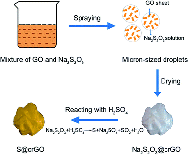
S@crGO in this work was prepared by a spray drying approach as depicted in Fig. 1. At the heating area in the furnace, Na2S2O3 precipitates out with the evaporation of water and was encapsulated by GO sheets. The GO sheets were crumpled by capillary compression constantly until the droplets dried completely. Meanwhile, the GO sheets were partially thermally reduced. S@crGO was acquired by filtration. TGA result (Fig. S1†) reveals that the S content in the composite cathode with GO to Na2S2O3 ratio of 1![[thin space (1/6-em)]](https://www.rsc.org/images/entities/char_2009.gif) :
:![[thin space (1/6-em)]](https://www.rsc.org/images/entities/char_2009.gif) 10, 1
10, 1![[thin space (1/6-em)]](https://www.rsc.org/images/entities/char_2009.gif) :
:![[thin space (1/6-em)]](https://www.rsc.org/images/entities/char_2009.gif) 12, and 1
12, and 1![[thin space (1/6-em)]](https://www.rsc.org/images/entities/char_2009.gif) :
:![[thin space (1/6-em)]](https://www.rsc.org/images/entities/char_2009.gif) 15 is ca. 55.6%, 66.0%, and 72.4%, respectively. Similar with that shown in our previous work,28,31 the pure graphene obtained by spray drying is paper-ball like with rich folds and wrinkles as evidenced by SEM observation (Fig. S2†). The paper-ball shapes were well maintained in the composite S@crGO (Fig. 2a and b) with an average particle size of ca. 500 nm. The size of the paper-ball can be readily regulated by tuning the preparation parameters.28 The folds and wrinkles can work as a buffer to accommodate the volume changes during charge/discharge cycling.31 Based upon the TEM results (Fig. 2c), the sulfur species are encapsulated by the graphene sheets. EDS elemental mapping (Fig. 2d) shows that C, S and O are rather homogeneously distributed but with less S concentration at the edge of particles, further proving that sulfur is encapsulated by GO sheets. The existence of O is due to the low drying temperature of 400 °C, which is not high enough to reduce GO completely. XRD result (Fig. S3†) shows characteristic diffraction peaks of sulfur along with the amorphous graphene host, similar with the reported results.21,34,35
15 is ca. 55.6%, 66.0%, and 72.4%, respectively. Similar with that shown in our previous work,28,31 the pure graphene obtained by spray drying is paper-ball like with rich folds and wrinkles as evidenced by SEM observation (Fig. S2†). The paper-ball shapes were well maintained in the composite S@crGO (Fig. 2a and b) with an average particle size of ca. 500 nm. The size of the paper-ball can be readily regulated by tuning the preparation parameters.28 The folds and wrinkles can work as a buffer to accommodate the volume changes during charge/discharge cycling.31 Based upon the TEM results (Fig. 2c), the sulfur species are encapsulated by the graphene sheets. EDS elemental mapping (Fig. 2d) shows that C, S and O are rather homogeneously distributed but with less S concentration at the edge of particles, further proving that sulfur is encapsulated by GO sheets. The existence of O is due to the low drying temperature of 400 °C, which is not high enough to reduce GO completely. XRD result (Fig. S3†) shows characteristic diffraction peaks of sulfur along with the amorphous graphene host, similar with the reported results.21,34,35
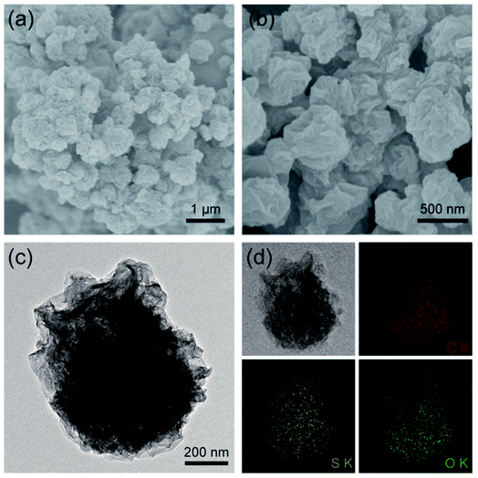 | ||
| Fig. 2 (a and b) SEM images at low and high magnifications, and (c) TEM image of S@crGO, (d) elemental mapping of C, S, and O in S@crGO. | ||
Since the S@crGO in this work was prepared by the in situ method with homogeneous mixture solution of GO and Na2S2O3 at 400 °C, the possible interaction between the S derived from Na2S2O3 and crumpled graphene host is examined by XPS. The corresponding survey spectrum (Fig. 3a) reveals the existence of C, S, and O, in agreement with the EDS results (Fig. 2d). High resolution C1s spectrum (Fig. 3b) shows that compared with the crumpled graphene host (Fig. S4†), S@crGO has an additional peak at 285.5 eV, corresponding to the C–S bond,21,36 which suggests the interaction between S and the crumpled graphene. The peaks at 284.8, 286.4, 287.2, and 288.9 eV are assigned to the sp2 hybridized carbon, C–O, C![[double bond, length as m-dash]](https://www.rsc.org/images/entities/char_e001.gif) O, and O–C
O, and O–C![[double bond, length as m-dash]](https://www.rsc.org/images/entities/char_e001.gif) O, respectively.36 The binding energy of 163.0 and 165.0 eV, ascribed to the S 2p3/2 and S 2p1/2 doublet with an energy separation of 1.2 eV,36 is slightly lower than that of elemental sulfur (164.0 and 165.2 eV), which reconfirms the presence of C–S bonding. The peak at 168.6 eV is owing to the presence of sulfate36 possibly formed by the oxidation of sulfur in air. The O 1s spectrum analysis reveals the existence of O-related surface functional groups, such as O
O, respectively.36 The binding energy of 163.0 and 165.0 eV, ascribed to the S 2p3/2 and S 2p1/2 doublet with an energy separation of 1.2 eV,36 is slightly lower than that of elemental sulfur (164.0 and 165.2 eV), which reconfirms the presence of C–S bonding. The peak at 168.6 eV is owing to the presence of sulfate36 possibly formed by the oxidation of sulfur in air. The O 1s spectrum analysis reveals the existence of O-related surface functional groups, such as O![[double bond, length as m-dash]](https://www.rsc.org/images/entities/char_e001.gif) C, O–S, and C–OH/C–O–C.36 Those polar surface functional groups are expected to immobilize the lithium polysulfides during cycling test and thus restrain the shuttling effect.
C, O–S, and C–OH/C–O–C.36 Those polar surface functional groups are expected to immobilize the lithium polysulfides during cycling test and thus restrain the shuttling effect.
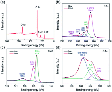 | ||
| Fig. 3 (a) Survey XPS spectrum of S@crGO, and corresponding high resolution spectra of (b) C, (c) S, and (d) O. | ||
To investigate the pore structure of the crumpled graphene host in the composite, the S@crGO samples were annealed at 400 °C for 1 h in N2 to evaporate the S species. The desulfurized crumpled graphene host and S@crGO were subjected to N2 gas sorption test. The isotherm sorption curve of graphene host (Fig. 4a) demonstrates the type IV curve, characteristics of mesopores. The BET surface area is 494.9 m2 g−1 and pore volume is 0.75 cm3 g−1. It shows mixed pore size distribution, with micropores (1–2 nm) and mesopores (2–5 nm). Compared with the pure crumpled graphene (Fig. S5†) prepared with the same procedure, the graphene host in S@crGO shows much higher surface area (494.9 vs. 121 m2 g−1) and pore volume (0.75 vs. 0.20 cm3 g−1), which is owing to the fact that the Na2S2O3 encapsulated in the graphene sheets suppress the further aggregation by capillary tension during drying. The high surface area and pore volume of crumpled graphene host make it possible for high S loading. Both the BET surface area and pore volume of S@crGO was dramatically lower than the crumpled graphene host, 19.4 m2 g−1 and 0.06 cm3 g−1, respectively, only 3.9% and 7.9% of the crumpled graphene host. Such significant decrease has been widely reported,13,34,35 which is due to the occupation of pores by S. The pore properties of crumpled graphene host and S@crGO are listed in Table 1. Further analysis reveals that the decline in the mesopore is larger than that of micropore, which is quite different from the conventional cathodes prepared by melt-diffusion, where micropore was preferentially occupied by S due to capillary force effect.13,34,35 The mesopores are generated mainly by the precipitation of Na2S2O3.
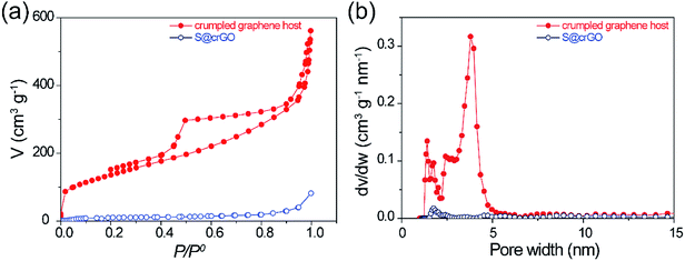 | ||
| Fig. 4 (a) N2 isothermal sorption curves of crumpled graphene host and S@crGO, (b) corresponding pore size distribution calculated by using the adsorption branch. | ||
| Sample | SBET (m2 g−1) | V (cm3 g−1) | ||||
|---|---|---|---|---|---|---|
| St | Smic | Smeso | Vt | Vmic | Vmeso | |
| Crumpled graphene host | 495 | 74.4 | 420.5 | 0.75 | 0.06 | 0.69 |
| S@crGO | 19.4 | 5.5 | 13.9 | 0.06 | 0.005 | 0.054 |
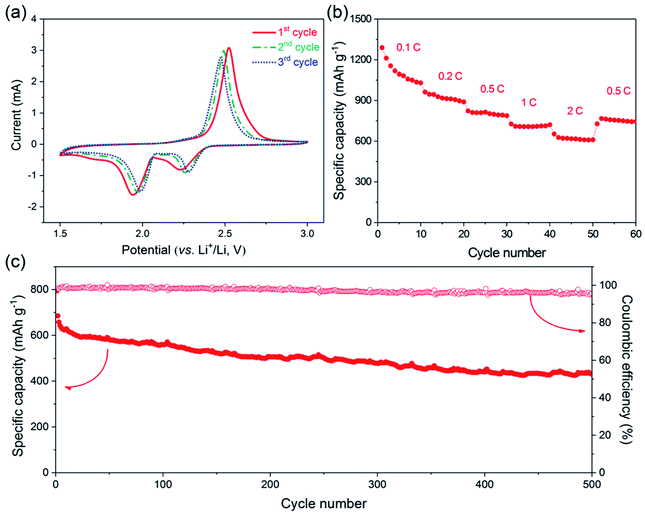
The electrochemical performance of the one-step prepared S@crGO as the cathode for Li–S batteries was tested in coin cells. The first three CV profiles at a scan rate of 0.5 mV s−1 in the potential range of 1.5–3.0 V vs. Li+/Li, are presented in Fig. 5a. The CV curves show two reduction peaks around 2.25 and 2.0 V, corresponding to the reduction of elemental sulfur to lithium polysulfides Li2Sx (2 < x ≤ 8) and further reduction to Li2S2 and Li2S. The oxidation peak around 2.5 V is assigned to the oxidation of Li2S2 and Li2S to S.1,37,38 The redox peaks shift with cycling, i.e., the reduction peaks shift to higher potentials whilst the oxidation peaks to lower potentials, which indicates that the reversibility is enhanced with cycling, at least the first three cycling.
The galvanostatic cycling performance of S@crGO at various current densities (0.1–2C, 1C = 1675 mA g−1) was then tested (Fig. S6†). Two reduction plateaus and single oxidation plateau are observed in the discharge/charge process, which are the typical characteristics of S–C cathodes.13,14,19,21,38 At the rate of 0.1C, the specific capacity is 1289 mA h g−1, 77% of the theoretical capacity (1675 mA h g−1). It should be noted that all the capacity was calculated based on the mass of S. The capacity declines to 962 mA h g−1 when the rate is doubled (0.2C). The rate capability was further evaluated with 10 cycles (Fig. 5b). The capacity decreases gradually with increasing C-rates. Nevertheless, an average capacity of 1112 mA h g−1 at 0.1C and 620 mA h g−1 at 2C was achieved. When the rate was reduced back to 0.5C, most of the capacity was recovered (751 vs. 803 mA h g−1). Such rate capability is better than some results reported.17,39 The long-term cycling performance of S@crGO as cathode for Li–S batteries was evaluated at a rate of 0.5C (Fig. 5c). It exhibits an initial discharge capacity of 794 mA h g−1 and remains a reversible capacity of 432 mA h g−1 after 500 cycles with capacity retention of 54.4%. The corresponding efficiency is higher than 95% over the whole cycle life. The cycling profiles of samples with 55.6% (1![[thin space (1/6-em)]](https://www.rsc.org/images/entities/char_2009.gif) :
:![[thin space (1/6-em)]](https://www.rsc.org/images/entities/char_2009.gif) 10) and 72.4% (1
10) and 72.4% (1![[thin space (1/6-em)]](https://www.rsc.org/images/entities/char_2009.gif) :
:![[thin space (1/6-em)]](https://www.rsc.org/images/entities/char_2009.gif) 15) S-loading at 0.5C was presented in Fig. S7.† Higher S-loading resulted in poor cycling performance, whilst lower S-loaded samples show comparable performance with its 66.0% counterpart.
15) S-loading at 0.5C was presented in Fig. S7.† Higher S-loading resulted in poor cycling performance, whilst lower S-loaded samples show comparable performance with its 66.0% counterpart.
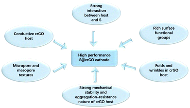
The high electrochemical performance of the present S@crGO cathode can be ascribed to several factors (Scheme 1). First, XPS results indicate strong interaction between the graphene host and sulfur, and also existence of rich oxygen-related surface functional groups. Keep in mind the graphene host in S@crGO is partially reduced graphene oxide and thus high electrical conductivity.28 Such strong interaction not only facilitates the electron transport at the interface of graphene and sulfur and thus fast rate capability, but also slows down the dissolution of lithium polysulfides into the electrolyte and thus better cycling stability.17–19,27 Second, as aforementioned, the crumpled graphene host shows micropore and mesopore textures. Pores of such size (micropore, 1–2 nm and mesopore, 2–5 nm) have been widely recognized to be very effective in immobilizing the lithium polysulfides and thus mitigate the shuttling effect, leading to enhanced cycling stability.12–14 In addition, the mesopores are easily accessible to the electrolyte and provide the fast channels for lithium ion transport, resulting in better rate capability.13,14,21,35 Finally, the folds and wrinkles in the crumpled graphene host can accommodate the volume changes accompanying S–Li2S transformation;31 meanwhile, the strong mechanical stability and aggregation-resist nature of crumpled graphene help maintain the stability of microstructure during cycling.38 Both contribute to improved cycling stability. It should be noted that although the shuttling effect can be suppressed by the present S@crGO, it cannot be completely eliminated as evidenced by the decay of the capacity with cycling (Fig. 5c). In addition, great room still remains to improve the utilization of sulfur at high discharge rates (0.5C, Fig. 5c), e.g., by optimization the pore properties and sulfur loading.34
Conclusions
Crumpled reduced graphene oxide-encapsulated sulfur was synthesized by a facile and scalable one-step in situ method. The resultant materials show good rate capability and decent cycling stability, which is derived from the advanced micro- and meso-pore textures, strong interaction between the crumpled graphene host and S, and rich surface oxygen functional groups. The Li–S battery with S@crGO cathode delivers specific capacity of 1112 and 620 mA h g−1 at respective 0.1 and 2C, and 432 mA h g−1 after 500 cycles at 0.5C. The synthesis protocols demonstrated here can be applied to prepare other crumpled graphene-based composites.Conflicts of interest
There are no conflicts to declare.Acknowledgements
This work was funded by the National Natural Science Foundation of China (Grant No. 51502197), Natural Science Foundation of Tianjin, China (Grant 15JCYBJC53100).References
- S. S. Zhang, J. Power Sources, 2013, 231, 153–162 CrossRef
.
- A. Manthiram, Y. Fu, S.-H. Chung, C. Zu and Y.-S. Su, Chem. Rev., 2014, 114, 11751–11787 CrossRef PubMed
.
- P. G. Bruce, S. A. Freunberger, L. J. Hardwick and J.-M. Tarascon, Nat. Mater., 2011, 11, 19 CrossRef PubMed
.
- B. Dunn, H. Kamath and J.-M. Tarascon, Science, 2011, 334, 928–935 CrossRef PubMed
.
- X. Liang, Z. Wen, Y. Liu, M. Wu, J. Jin, H. Zhang and X. Wu, J. Power Sources, 2011, 196, 9839–9843 CrossRef
.
- Y. Yang, G. Zheng and Y. Cui, Chem. Soc. Rev., 2013, 42, 3018–3032 RSC
.
- S. Zhang, K. Ueno, K. Dokko and M. Watanabe, Adv. Energy Mater., 2015, 5, 1500117 CrossRef
.
- J.-Q. Huang, Q. Zhang and F. Wei, Energy Storage Materials, 2015, 1, 127–145 CrossRef
.
- C. Xu, Y. Wu, X. Zhao, X. Wang, G. Du, J. Zhang and J. Tu, J. Power Sources, 2015, 275, 22–25 CrossRef
.
- J. Zhang, Z. Dong, X. Wang, X. Zhao, J. Tu, Q. Su and G. Du, J. Power Sources, 2014, 270, 1–8 CrossRef
.
- J. Zhang, J. Xiang, Z. Dong, Y. Liu, Y. Wu, C. Xu and G. Du, Electrochim. Acta, 2014, 116, 146–151 CrossRef
.
- X. Ji, K. T. Lee and L. F. Nazar, Nat. Mater., 2009, 8, 500 CrossRef PubMed
.
- G. He, X. Ji and L. Nazar, Energy Environ. Sci., 2011, 4, 2878–2883 Search PubMed
.
- C. Liang, N. J. Dudney and J. Y. Howe, Chem. Mater., 2009, 21, 4724–4730 CrossRef
.
- J. Guo, J. Zhang, F. Jiang, S. Zhao, Q. Su and G. Du, Electrochim. Acta, 2015, 176, 853–860 CrossRef
.
- J. Zhang, H. Huang, J. Bae, S.-H. Chung, W. Zhang, A. Manthiram and G. Yu, Small Methods, 2018, 2, 1700279 CrossRef
.
- L. Ji, M. Rao, H. Zheng, L. Zhang, Y. Li, W. Duan, J. Guo, E. J. Cairns and Y. Zhang, J. Am. Chem. Soc., 2011, 133, 18522–18525 CrossRef PubMed
.
- J. Song, T. Xu, M. L. Gordin, P. Zhu, D. Lv, Y.-B. Jiang, Y. Chen, Y. Duan and D. Wang, Adv. Funct. Mater., 2014, 24, 1243–1250 CrossRef
.
- Y. Qiu, W. Li, W. Zhao, G. Li, Y. Hou, M. Liu, L. Zhou, F. Ye, H. Li, Z. Wei, S. Yang, W. Duan, Y. Ye, J. Guo and Y. Zhang, Nano Lett., 2014, 14, 4821–4827 CrossRef PubMed
.
- J. Zhang, Y. Shi, Y. Ding, L. Peng, W. Zhang and G. Yu, Adv. Energy Mater., 2017, 7, 1602876 CrossRef
.
- G. Li, J. Sun, W. Hou, S. Jiang, Y. Huang and J. Geng, Nat. Commun., 2016, 7, 10601 CrossRef PubMed
.
- N. Jayaprakash, J. Shen, S. S. Moganty, A. Corona and L. A. Archer, Angew. Chem., 2011, 123, 6026–6030 CrossRef
.
- J. Zhang, Y. Shi, Y. Ding, W. Zhang and G. Yu, Nano Lett., 2016, 16, 7276–7281 CrossRef PubMed
.
- A. K. Geim and K. S. Novoselov, Nat. Mater., 2007, 6, 183 CrossRef PubMed
.
- H. Wang, Y. Yang, Y. Liang, J. T. Robinson, Y. Li, A. Jackson, Y. Cui and H. Dai, Nano Lett., 2011, 11, 2644–2647 CrossRef PubMed
.
- H. Al Salem, G. Babu, C. V. Rao and L. M. R. Arava, J. Am. Chem. Soc., 2015, 137, 11542–11545 CrossRef PubMed
.
- G. Zhou, L.-C. Yin, D.-W. Wang, L. Li, S. Pei, I. R. Gentle, F. Li and H.-M. Cheng, ACS Nano, 2013, 7, 5367–5375 CrossRef PubMed
.
- J. Luo, H. D. Jang, T. Sun, L. Xiao, Z. He, A. P. Katsoulidis, M. G. Kanatzidis, J. M. Gibson and J. Huang, ACS Nano, 2011, 5, 8943–8949 CrossRef PubMed
.
- H. Chen, C. Chen, Y. Liu, X. Zhao, N. Ananth, B. Zheng, L. Peng, T. Huang, W. Gao and C. Gao, Adv. Energy Mater., 2017, 7, 1700051 CrossRef
.
- J. Song, Z. Yu, M. L. Gordin and D. Wang, Nano Lett., 2016, 16, 864–870 CrossRef PubMed
.
- J. Luo, X. Zhao, J. Wu, H. D. Jang, H. H. Kung and J. Huang, J. Phys. Chem. Lett., 2012, 3, 1824–1829 CrossRef PubMed
.
- W. S. Hummers and R. E. Offeman, J. Am. Chem. Soc., 1958, 80, 1339 CrossRef
.
- Y. V. Mikhaylik, US Pat., US8828610B2, 2008
.
- X. Li, Y. Cao, W. Qi, L. V. Saraf, J. Xiao, Z. Nie, J. Mietek, J.-G. Zhang, B. Schwenzer and J. Liu, J. Mater. Chem., 2011, 21, 16603–16610 RSC
.
- S.-R. Chen, Y.-P. Zhai, G.-L. Xu, Y.-X. Jiang, D.-Y. Zhao, J.-T. Li, L. Huang and S.-G. Sun, Electrochim. Acta, 2011, 56, 9549–9555 CrossRef
.
- J. Moulder, W. Stickle, P. Sobol and K. Bomben, Handbook of X-Ray Photoelectron Spectroscopy, Perkin-Elmer Corporation, USA, 1992 Search PubMed
.
- S.-E. Cheon, K.-S. Ko, J.-H. Cho, S.-W. Kim, E.-Y. Chin and H.-T. Kim, J. Electrochem. Soc., 2003, 150, A796–A799 CrossRef
.
- S.-E. Cheon, K.-S. Ko, J.-H. Cho, S.-W. Kim, E.-Y. Chin and H.-T. Kim, J. Electrochem. Soc., 2003, 150, A800–A805 CrossRef
.
- C. Zhang, H. B. Wu, C. Yuan, Z. Guo and X. W. Lou, Angew. Chem., 2012, 124, 9730–9733 CrossRef
.
Footnote |
| † Electronic supplementary information (ESI) available: TG plot, XRD pattern and charge–discharge profile of S@crGO, SEM image and BET curve of crGO, and XPS spectra of crumpled graphene host. See DOI: 10.1039/c8ra03255f |
| This journal is © The Royal Society of Chemistry 2018 |

