DOI:
10.1039/C8RA03290D
(Paper)
RSC Adv., 2018,
8, 20877-20883
Reciprocating sliding wear of hybrid PTFE/Kevlar fabric composites along different orientations
Received
17th April 2018
, Accepted 23rd May 2018
First published on 7th June 2018
Abstract
The dry reciprocating sliding properties of two weaves, reinforced twill 2/2 (RT) and basket weave 3/3 (BW), of hybrid PTFE/Kevlar fabric composites were investigated using a pin-on-flat configuration along the selected orientations of 0°, 30°, 45°, 60° and 90° which were the reciprocating sliding directions of pin to weft yarn (PTFE). The morphologies of the worn surfaces of the composites were analyzed by means of Scanning Electron Microscopy (SEM). The PTFE transfer film and F element on the counterface were observed and analyzed respectively by SEM and Energy Dispersive X-ray Spectroscopy (EDS). The results showed that the orientations and weaves played an important role in the friction reduction and antiwear properties of PTFE/Kevlar fabric composites. Contrasting to BW PTFE/Kevlar fabric composites, RT PTFE/Kevlar fabric composites showed significant advantages in the antiwear performance along all the selected orientations. The main damage forms of PTFE/Kevlar fabric composites include fatigue wear and adhesive wear of the polymer matrix, and lifted, wrinkled and breakage of the fibers.
1. Introduction
Fabric reinforced polymer matrix composites are used frequently in many engineering applications, such as aviation, automotive and civil engineering by virtue of their good self-lubricating abilities, light weight, excellent antiwear performances, and dimensional stability.1–3 The tribological properties of fabric reinforced polymer matrix composites are determined by a number of parameters such as materials (amount and type of fibers, resins, fillers and so on), textile structures of fabrics (plain, twill, satin and so on), processing techniques (curing, bonding, fiber surface treatment and so on), and working conditions (load, sliding velocity, environment temperature and so on).4 Thus, the friction and wear mechanisms are extremely complex and influenced by a numerous factors which occurred in the contact interface of the friction pair.5 For fabric reinforced polymer matrix composites, the reinforcing fabrics play a crucial role in maintaining the strength and tribological behaviors. By the integration of the low friction of PTFE fibers and the high strength and good wear-resistant of Kevlar fibers, hybrid PTFE/Kevlar fabric composites have better anti-friction and wear-resistant performances and been drawing more attentions of the researchers in recent years, especially in the bearing applications.
In order to develop a good tribo-composite, the tribological performances of hybrid PTFE/Kevlar fabric composites reinforced with different types and scales of particles have already been investigated.6 Yin et al.7 filled hybrid PTFE/Kevlar fabric composites with nano-Si3N4 and submicron WS2, and found that the wear rate and friction coefficient of 7.5 wt% WS2 + 12.5 wt% Si3N4 filled hybrid PTFE/Kevlar fabric composites were much less than those of the unfilled composites. Comparing with graphite and grapheme,8 the antiwear property and load carrying capacity of the 2 wt% graphene oxide filled hybrid PTFE/Nomex fabric composite were improved obviously. Zhang et al.9 studied the sliding wear performances of hybrid PTFE/Kevlar fabric/phenolic composites filled with TiO2 and SiO2 nanoparticles. The results indicated that 5 wt% TiO2 nanoparticles were effective in reducing wear of hybrid PTFE/Kevlar fabric/phenolic composite at elevated temperatures while SiO2 nanoparticles increased wear. In other studies, the bonding strengths of the fibers and resin interfaces were proved to be important factors in the antiwear performance of fabric composites.10 Various surface treatment methods such as plasma treatment11,12 and strong HNO3 oxidation13 were applied to modify the surface of the fibers. Surface modification could change the surface morphology and reactivity of the fibers. And a quantity of the functional groups were introduced into the surfaces of the fibers, which leaded to an improvement in the bonding strength between the fibers and the resin matrix. Thus the tribological properties of fabric composites were improved.14,15 The effect of textile structures on the tribological properties of hybrid PTFE/Kevlar fabric/phenolic composites also have been studied.16,17 Qi et al.18 investigated the role of the weft densities in the tribological properties of hybrid PTFE/Kevlar fabric composites. And they found that the broken twill weave with the weft densities range in 300 and 350 roots per 10 cm showed the better anti-friction and wear-resistant performances. Li et al.19 reported that the reducing of the weave densities of hybrid PTFE/Kevlar fabric composites could reduce the wear rate but increase the friction coefficient.
Although the friction coefficients and wear rates of fabric composites were affected by the fabric orientations relative to the sliding directions,20–22 the significances of the fabric orientations in the tribological characteristics of hybrid PTFE/Kevlar fabric composites are not much explored. Hence, in this paper, an attempt has been made to investigate the dry friction and wear behaviors and mechanisms of two weaves of hybrid PTFE/Kevlar fabric composites reciprocating sliding along different orientations.
2. Experimental
2.1. Materials and specimen preparation
The hybrid PTFE/Kevlar fabrics were weaved out of PTFE fibers and Kevlar-49 fibers (Du Pont, USA). The warp yarn was Kevlar and the weft yarn was PTFE. Two types of weaves, reinforced twill 2/2 (RT) and basket weave 3/3 (BW) were used as a comparison. Simulations of three dimensional (3D) structures and plane sketches of the two weaves of PTFE/Kevlar fabrics are shown in Fig. 1. The properties of the 204 phenolic adhesive resins (Shanghai Xinguang Chemical Plant, China) are listed in Table 1.
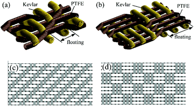 |
| | Fig. 1 Schematics of 3D structures and weaves of PTFE/Kevlar fabrics. (a) 3D of RT, (b) 3D of BW, (c) RT and (d) BW. | |
Table 1 Physical properties and used conditions of the 204 phenolic resin
| Curing temperature |
Operating temperature |
Shear strength |
Curing pressure |
Curing time |
| 180 °C |
−70 to 200 °C |
≥15 MPa |
0.2 MPa |
2 h |
The manufacturing process of hybrid PTFE/Kevlar fabric composite is shown in Fig. 2. The hybrid PTFE/Kevlar fabrics were dipped and cleaned in the acetone for 12 h, boiled 20 min in the distilled water, and dried in the oven at 80 °C for 1 h. Then, the hybrid PTFE/Kevlar fabrics were immersed in the phenolic resin and treated by the ultrasonic oscillation for 3 h. A glass rod was used to roll on the PTFE/Kevlar fabric and to ensure that no bubbles were presented on the fabric surface to make the resin fully and uniformly saturate the fabric. Subsequently, the fabric was once again dried in the drying oven at 110 °C for 1 h. A series of test specimens of hybrid PTFE/Kevlar composites were fabricated by the preparation method. Fig. 3 shows the unwear images of RT and BW hybrid PTFE/Kevlar fabric composites. The relative mass fractions of the resins to RT and BD PTFE/Kevlar composites are about 16 ± 5% and 17 ± 3% respectively. The thicknesses of RT and BD PTFE/Kevlar composites are 0.37 ± 0.02 mm and 0.51 ± 0.04 mm respectively.
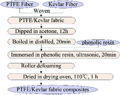 |
| | Fig. 2 Manufacturing process of hybrid PTFE/Kevlar fabric composites. | |
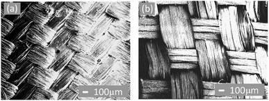 |
| | Fig. 3 (a) RT and (b) BW hybrid PTFE/Kevlar fabric composites. | |
2.2 Friction and wear test
The friction and wear behaviors of hybrid PTFE/Kevlar fabric composites were performed on a pin-on-flat reciprocating sliding tribometer (CETR UMT Multi-Specimen Test System, USA) under dry friction and ambient temperature conditions. Fig. 4(a) shows the schematic of the pin-on-flat configuration. A cylindrical pin (AISI 304 stainless steel), with the diameter of 3 mm, was used to slid against a square flat (AISI 304 stainless steel), with the size of 43 mm × 43 mm, on which hybrid PTFE/Kevlar fabric composite (40 mm × 40 mm) was bonded as the friction face. The pre-treatment approaches of the pin and flat were listed as follows. The flat was polished with the 150# and 400# water sandpapers. The pin was polished with the 600#, 800# and 1200# water sandpapers (surface roughness Ra is about 0.15 μm). Both the pin and flat were cleaned for 15 min in the alcohol using an ultrasonic cleaner. Hybrid PTFE/Kevlar fabric composite was bonded to the surface of the flat with a small amount of the phenolic adhesive resin. Then, the fabric composite was cured at 180 °C for 2 h under the contact pressure 0.2 MPa. The pin was kept stationary and hybrid PTFE/Kevlar fabric composite reciprocated sliding with the flat under a prescribed set of working condition. The reciprocating frequency and stroke length were fixed to 5 Hz and 10 mm, respectively. The normal load was 8 MPa (56.5 N) and the total number of reciprocating were 27![[thin space (1/6-em)]](https://www.rsc.org/images/entities/char_2009.gif) 000 cycles (sliding distance 540 m). Fig. 4(b) shows the selected orientations of 0°, 30°, 45°, 60° and 90° which are defined as the reciprocating sliding direction to the weft yarn (PTFE). The reciprocating sliding test of each orientation was repeated three times to evaluate statistical repeatability. At the end of each test, the hybrid PTFE/Kevlar fabric composite was placed on a moving horizontally platform and the wear depth was measured by a micrometer (digital display, diameter of the measuring head 1 mm, resolution 0.001 mm) fixed by a fixture with 7 different points of the reciprocating stroke length. The wear performance was expressed by the specific wear rate calculated by the following equation ω = ΔV/(FL), where ω is the specific wear rate in m3 (N m)−1, ΔV is the volume loss in m3, F is the applied normal load in N, L is the total sliding distance in m. The worn surfaces of the pins and hybrid PTFE/Kevlar fabric composites were examined by Scanning Electron Microscopy (SEM). In addition, Energy Dispersive X-ray Spectroscopy (EDS) was used for the determination of the elemental distribution of the PTFE transfer film on the surface of the pin.
000 cycles (sliding distance 540 m). Fig. 4(b) shows the selected orientations of 0°, 30°, 45°, 60° and 90° which are defined as the reciprocating sliding direction to the weft yarn (PTFE). The reciprocating sliding test of each orientation was repeated three times to evaluate statistical repeatability. At the end of each test, the hybrid PTFE/Kevlar fabric composite was placed on a moving horizontally platform and the wear depth was measured by a micrometer (digital display, diameter of the measuring head 1 mm, resolution 0.001 mm) fixed by a fixture with 7 different points of the reciprocating stroke length. The wear performance was expressed by the specific wear rate calculated by the following equation ω = ΔV/(FL), where ω is the specific wear rate in m3 (N m)−1, ΔV is the volume loss in m3, F is the applied normal load in N, L is the total sliding distance in m. The worn surfaces of the pins and hybrid PTFE/Kevlar fabric composites were examined by Scanning Electron Microscopy (SEM). In addition, Energy Dispersive X-ray Spectroscopy (EDS) was used for the determination of the elemental distribution of the PTFE transfer film on the surface of the pin.
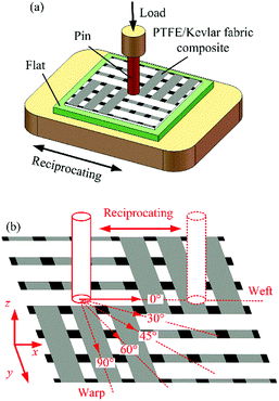 |
| | Fig. 4 Schematic of (a) pin-on-flat configuration, (b) orientations of sliding directions to weft yarn of PTFE/Kevlar fabric composites. | |
3. Results and discussion
The representative variations of the friction coefficient as a function of the sliding time of RT and BW PTFE/Kevlar fabric composites during the reciprocating sliding test, respectively, along orientations of 0° and 90° are shown in Fig. 5. In general, the friction coefficients of RT and BW PTFE/Kevlar fabric composites along orientations of 0° and 90° achieve a relatively stable state after a short running-in period. And then the friction coefficients increase slowly and stably with the sliding time. Due to the influence of the textile structures (as shown in Fig. 1 and 4), the distribution of the material components on the surface under different orientations and along the thickness direction of RT and BW PTFE/Kevlar fabric composites are uneven.17,23 The contact geometry changes with the wear depth during the reciprocating sliding. The slow increasing of the friction coefficients could be caused by the variation of the material component distribution for the change of the contact geometry.
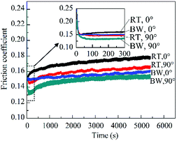 |
| | Fig. 5 Variations of friction coefficient with sliding time for RT and BW along orientations of 0° and 90° (load 8 MPa, reciprocating frequency 5 Hz). | |
The average friction coefficients in the steady-state (calculated by the average of the last 4400 s) for RT and BW PTFE/Kevlar fabric composites under different orientations of 0°, 30°, 45°, 60° and 90° are summarized in Fig. 6 as histograms. In Fig. 6, for RT PTFE/Kevlar fabric composites, the average friction coefficients are different along different orientations. The maximum value of the average friction coefficient is about 0.18 appearing in the 0° orientation and the minimum is about 0.15 in the 30° orientation. But for BW PTFE/Kevlar fabric composites, the average friction coefficient along the 45° orientation is the lowest about 0.15. While there are slight differences of the average friction coefficients along the orientations of 0°, 30°, 60°, and 90°. In addition, the average friction coefficients of RT and BW in each orientation are different, but in fact the differences are not obvious along the orientations of 30°, 45°, 60° and 90° except for that along the orientation of 0°.
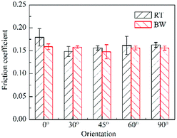 |
| | Fig. 6 The average friction coefficients of RT and BW PTFE/Kevlar fabric composites with different orientations. | |
Overall, the lowest friction coefficients of both RT and BW PTFE/Kevlar fabric composites are about 0.15 which are not ideal results as a kind of self-lubricating materials. The working conditions and the formation of the transfer film on the pin surface are considered to be the main reasons. The friction coefficients of pure PTFE and its composites decrease with the increase of the load and velocity.24–26 When the loads increase from 5 MPa to 30 MPa (all under 13 Hz), the steady-state friction coefficients of plain weave PTFE/Kevlar fabric composites were reduced from 0.10–0.11 to 0.06–0.07.16 The load and frequency used in this experiment are relatively low comparing with ref. 16. Thus, the friction coefficient is relatively high. In addition, a uniform and thick PTFE transfer film on the counterface plays an important role in the reduction of the friction coefficients of PTFE composites.27–30 So the distribution of the PTFE transfer film on the counterface was analyzed. Fig. 7 and 8 give SEM micrographs and EDS images of the pin surfaces, respectively, of RT PTFE/Kevlar fabric composites sliding along the orientation of 30° and of BW PTFE/Kevlar fabric composites sliding along the orientation of 45° after the tests. As shown in Fig. 7(b) and 8(b), the distributions of F element (from PTFE) on the pin surface are uniform, but the PTFE transfer films are difficult to be observed from SEM micrographs (Fig. 7(a) and 8(a)), indicating the PTFE transfer films are rare and very thin. This is also regarded as the cause for the high friction coefficient of RT and BW PTFE/Kevlar fabric composites in these tests.
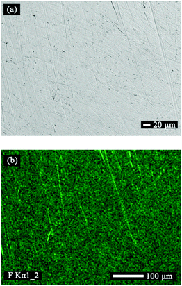 |
| | Fig. 7 (a) SEM image and (b) EDS mapping of F element distribution for the pin surface after tribo-testing with RT PTFE/Kevlar fabric composite along the orientation of 30°. | |
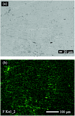 |
| | Fig. 8 (a) SEM image and (b) EDS mapping of F element distribution for the pin surface after tribo-testing with BW PTFE/Kevlar fabric composite along the orientation of 45°. | |
Fig. 9 shows the wear depths and wear rates of RT and BW PTFE/Kevlar fabric composites with different orientations. As seen in Fig. 9, the wear rates of RT PTFE/Kevlar fabric composites along all the orientations are in the range of (1.1–1.6) × 10−14 m3 (N m)−1. RT PTFE/Kevlar fabric composites show the better wear resistance when sliding along the orientations of 60° and 90° and the worse wear resistance along 0° and 45°. The wear resistance performance of RT PTFE/Kevlar fabric composite is moderate when sliding along the orientation of 30°, which is slightly inferior to the orientations of 60° and 90°. In the case of BW PTFE/Kevlar fabric composites, the wear rates increase dramatically comparing with RT and are about 2–2.5 times of RT along each orientation. The lowest wear rate appears in the orientation of 60° and the highest wear rate in 90°. It is shown that the wear resistance performances of PTFE/Kevlar fabric composites are not only influenced by the orientations but also largely affected by the weaves of fabrics.4,16 As seen in Fig. 1, for RT, the warp yarns (Kevlar) and weft yarns (PTFE) are interlaced once every two yarns, but for BW the warp yarns and weft yarns are interlaced once every three yarns. In other words, the floatings (defined as the length of the warp or weft yarn between two adjacent interlaced points) of the warp yarn and weft yarn of RT are shorter than that of BW. In the textile, the more of the interlaced points and the shorter of the floatings for the warp and weft yarns will make the fabric stiff, flat and wear-resisting. This is considered to be the reason why the wear-resisting performance of BW PTFE/Kevlar fabric composite is worse than that of RT. Moreover, no matter for RT or BW PTFE/Kevlar fabric composites, the variation of the material component distribution due to the change of the contact geometry is also considered to be a major factor for the difference of the wear rates along different orientations. For RT PTFE/Kevlar fabric composite, as seen in Fig. 1(c), the distribution of PTFE is almost continuous along the orientation of 45° and the proportion of PTFE is also higher, comparing with other orientations. Thus the friction coefficient along the orientation of 45° is lower than that along the orientations of 0°, 60° and 90°, and the antiwear performance is worse than that along the orientations of 30°, 60° and 90°.
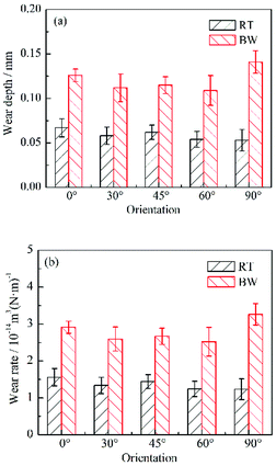 |
| | Fig. 9 (a) The wear depths and (b) wear rates of RT and BW PTFE/Kevlar fabric composites with different orientations. | |
SEM images of the worn surfaces of fabric composites were done to understand the wear mechanisms. Fig. 10 and 11 show the morphologies of the worn surfaces of RT and BW PTFE/Kevlar fabric composites, respectively, along different orientations. In all the images, the sliding direction of the pin is horizontal. It can be seen that the worn surfaces of RT PTFE/Kevlar fabric composites along the orientations of 30°, 60° and 90° are quite smooth. Severe degradation of the resin matrix and fibers' breakage occurred on the worn surface of RT PTFE/Kevlar fabric composites along the orientations of 0° and 45°. As shown in Fig. 10(a) and (c), a small amount of fibers were cut off accompanying with the resin matrix being peeled off. And masses of cracks are observed (also in Fig. 10(d) and (e)) indicating severe fatigue wear occurred on the worn surface. Fig. 11(a) shows the worn surface of BW PTFE/Kevlar fabric composite along the orientation of 0°. It is observed from Fig. 11(a) that bundles of fibers are exposed on the worn surface and severely damaged. The most serious damage for BW PTFE/Kevlar fabric composites occurred on the worn surface that along the orientation of 90°, which fibers were micro-cut, lifted and wrinkled (as seen in Fig. 11(e)) corresponding to its poor wear-resistance in Fig. 9(b). Comparing with the orientations of 0° and 90°, the worn surfaces of BW PTFE/Kevlar fabric composites along the orientations of 30°, 45° and 60° are not severely destroyed. And the irregular peeling edge of the resin matrix and wear debris (as seen in Fig. 11(d) and (e)) indicated that adhesive wear and the extrusion effect of normal force are also the main damage form of the resin matrix.
 |
| | Fig. 10 SEM images of the worn surfaces of RT PTFE/Kevlar fabric composites along orientations of (a) 0°, (b) 30°, (c) 45°, (d) 60° and (e) 90°. | |
 |
| | Fig. 11 SEM images of the worn surfaces of BW PTFE/Kevlar fabric composites along orientations of (a) 0°, (b) 30°, (c) 45°, (d) 60° and (e) 90°. | |
4. Conclusions
During the dry reciprocating sliding test against 304 stainless steel pin, the friction coefficients of RT and BW PTFE/Kevlar fabric composites achieved a relatively stable state after a short running-in period. The friction coefficients along different orientations were ranked as, 30° < 45° < 60° ≈ 90° < 0° for RT PTFE/Kevlar fabric composites and 45° < 0° ≈ 30° ≈ 60° ≈ 90° for BW. The lowest friction coefficients of RT and BW PTFE/Kevlar fabric composites are similar about 0.15, caused by the rare and thin PTFE transfer film on the counterface. The order of the wear rates along different orientations are listed as follows, 60° ≈ 90° < 30° < 45° < 0° for RT PTFE/Kevlar fabric composite and 60° < 30° < 45° < 0° < 90° for BW. The weave also has a significant effect on the wear properties of PTFE/Kevlar fabric composites and the wear rates of BW are about 2–2.5 times to RT along each orientation. The main damage forms of PTFE/Kevlar fabric composites include fatigue wear and adhesive wear of the polymer matrix, and lifted, wrinkled and breakage of the fibers.
Conflicts of interest
There are no conflicts.
Acknowledgements
This work was supported by National Natural Science Foundation of China (Grant No. 51405422), Natural Science Foundation of Hebei Province (Grant No. E2015203113, E2016203103), Youth Projects of Department of Education of Hebei Province (Grant No. QN2017148).
Notes and references
- K. Kato, Wear, 2000, 241, 151–157 CrossRef.
- W. R. Jones Jr and M. J. Jansen, Proc. Inst. Mech. Eng., Part J, 2008, 222, 997–1004 CrossRef.
- G. Ren, Z. Zhang, Y. Song, X. Li, J. Yan, Y. Wang and X. Zhu, Compos. Sci. Technol., 2017, 146, 155–160 CrossRef.
- J. Bijwe and R. Rattan, Wear, 2007, 263, 984–991 CrossRef.
- J. A. Williams, Tribol. Int., 2005, 38, 863–870 CrossRef.
- M. Yang, Z. Zhang, J. Yuan, F. Guo, X. Men and W. Liu, RSC Adv., 2016, 6, 110070–110076 RSC.
- H. L. Li, Z. W. Yin, D. Jiang, J. H. Ya and Y. Q. Cui, Tribol. Int., 2014, 80, 172–178 CrossRef.
- G. N. Ren, Z. Z. Zhang, X. T. Zhu, X. H. Men and W. M. Liu, J. Mater. Sci., 2014, 49, 3716–3724 CrossRef.
- H. J. Zhang, Z. Z. Zhang and F. Guo, Tribol. Trans., 2010, 53, 678–683 CrossRef.
- S. Tiwari, J. Bijwe and S. Panier, Tribol. Int., 2011, 44, 782–788 CrossRef.
- H. J. Zhang, Z. Z. Zhang and F. Guo, J. Appl. Polym. Sci., 2009, 114, 3980–3986 CrossRef.
- F. H. Su, Z. Z. Zhang, F. Guo, X. H. Men and W. M. Liu, Compos. Sci. Technol., 2007, 67, 981–988 CrossRef.
- X. R. Zhang, X. Q. Pei, Q. Jia and Q. H. Wang, Appl. Phys. A, 2009, 95, 793–799 CrossRef.
- H. J. Zhang, Z. Z. Zhang, F. Guo and W. M. Liu, Polym. Compos., 2009, 30, 1523–1531 CrossRef.
- M. M. Yang, J. Y. Yuan, F. Guo, K. Wang, Z. Z. Zhang, X. H. Men and W. M. Liu, Eur. Polym. J., 2016, 78, 163–172 CrossRef.
- D. P. Gu, Y. L. Yang, X. W. Qi, W. Deng and L. Shi, Chin. J. Mech. Eng., 2012, 25, 1044–1051 CrossRef.
- D. P. Gu, Y. L. Yang, S. W. Chen and W. W. Su, Autex Res. J., 2014, 14, 168–173 Search PubMed.
- X. W. Qi, J. Ma, Z. N. Jia, Y. L. Yang and H. B. Gao, Wear, 2014, 318, 124–129 CrossRef.
- H. L. Li, Z. W. Yin, D. Jiang and Y. J. Li, Ind. Lubr. Tribol., 2016, 68, 278–286 CrossRef.
- J. Bijwe, S. Awtade and A. Ghosh, Wear, 2006, 260, 401–411 CrossRef.
- P. Samyn, J. Compos. Mater., 2017, 51, 221–240 CrossRef.
- M. Sharma, I. M. Rao and J. Bijwe, Wear, 2009, 267, 839–845 CrossRef.
- N. G. Koltysheva, S. V. Lomov and N. N. Truevtzev, Autex Res. J., 2004, 4, 182–186 Search PubMed.
- D. P. Gu, C. S. Duan, B. L. Fan, S. W. Chen and Y. L. Yang, Tribol. Int., 2016, 103, 423–431 CrossRef.
- D. M. Nuruzzaman, M. A. Chowdhury and M.
L. Rahaman, Ind. Lubr. Tribol., 2011, 63, 320–326 CrossRef.
- H. Unal, A. Mimaroglu, U. Kadıoglu and H. Ekiz, Mater. Des., 2004, 25, 239–245 CrossRef.
- Y. X. Wang and F. Y. Yan, Wear, 2006, 261, 1359–1366 CrossRef.
- J. Ye, H. S. Khare and D. L. Burris, Wear, 2013, 297, 1095–1102 CrossRef.
- E. Padenko, L. J. van Rooyen and J. Karger-Kocsis, Tribol. Lett., 2017, 65, 36 CrossRef.
- M. H. Cho, Journal of Mechanical Science and Technology, 2009, 23, 2291–2298 CrossRef.
|
| This journal is © The Royal Society of Chemistry 2018 |
Click here to see how this site uses Cookies. View our privacy policy here.  Open Access Article
 *ab,
Longxiao Zhanga,
Suwen Chen
 *c,
Kefeng Songa and
Shouyao Liua

![[thin space (1/6-em)]](https://www.rsc.org/images/entities/char_2009.gif) 000 cycles (sliding distance 540 m). Fig. 4(b) shows the selected orientations of 0°, 30°, 45°, 60° and 90° which are defined as the reciprocating sliding direction to the weft yarn (PTFE). The reciprocating sliding test of each orientation was repeated three times to evaluate statistical repeatability. At the end of each test, the hybrid PTFE/Kevlar fabric composite was placed on a moving horizontally platform and the wear depth was measured by a micrometer (digital display, diameter of the measuring head 1 mm, resolution 0.001 mm) fixed by a fixture with 7 different points of the reciprocating stroke length. The wear performance was expressed by the specific wear rate calculated by the following equation ω = ΔV/(FL), where ω is the specific wear rate in m3 (N m)−1, ΔV is the volume loss in m3, F is the applied normal load in N, L is the total sliding distance in m. The worn surfaces of the pins and hybrid PTFE/Kevlar fabric composites were examined by Scanning Electron Microscopy (SEM). In addition, Energy Dispersive X-ray Spectroscopy (EDS) was used for the determination of the elemental distribution of the PTFE transfer film on the surface of the pin.
000 cycles (sliding distance 540 m). Fig. 4(b) shows the selected orientations of 0°, 30°, 45°, 60° and 90° which are defined as the reciprocating sliding direction to the weft yarn (PTFE). The reciprocating sliding test of each orientation was repeated three times to evaluate statistical repeatability. At the end of each test, the hybrid PTFE/Kevlar fabric composite was placed on a moving horizontally platform and the wear depth was measured by a micrometer (digital display, diameter of the measuring head 1 mm, resolution 0.001 mm) fixed by a fixture with 7 different points of the reciprocating stroke length. The wear performance was expressed by the specific wear rate calculated by the following equation ω = ΔV/(FL), where ω is the specific wear rate in m3 (N m)−1, ΔV is the volume loss in m3, F is the applied normal load in N, L is the total sliding distance in m. The worn surfaces of the pins and hybrid PTFE/Kevlar fabric composites were examined by Scanning Electron Microscopy (SEM). In addition, Energy Dispersive X-ray Spectroscopy (EDS) was used for the determination of the elemental distribution of the PTFE transfer film on the surface of the pin.


