 Open Access Article
One-step fabrication of polyamide 6 hollow fibre membrane using non-toxic diluents for organic solvent nanofiltration†
Sungil Jeon*a,
Atsushi Nishitania,
Liang Chenga,
Li-Feng Fanga,
Noriaki Katoa,
Takuji Shintanib and
Hideto Matsuyama *a
*a
aCenter for Membrane and Film Technology, Department of Chemical Science and Engineering, Kobe University, 1-1 Rokkodai-cho, Nada-ku, Kobe, Hyogo 657-8501, Japan. E-mail: sungil.jeon@people.kobe-u.ac.jp; matuyama@kobe-u.ac.jp
bCenter for Membrane and Film Technology, Graduate School of Science, Technology and Innovation, Kobe University, 1-1 Rokkodai-cho, Nada-ku, Kobe, Hyogo 657-8501, Japan
First published on 30th May 2018
Abstract
We developed new polyamide 6 hollow fibre membranes using a green process to fabricate cutting-edge “organic solvent nanofiltration” membranes by one-step spinning process for organic solvent separation. This economic and sustainable membrane showed good rejection and durability performance in various organic solvents.
Organic solvent nanofiltration (OSN) process is one of the emerging separation technologies used extensively in various industries such as petrochemical, pharmaceutical, chemical, and food for the purification or separation of organic solvents.1,2 The OSN process has low energy consumption and low operation costs compared with conventional separation processes such as evaporation, distillation, and adsorption.1,3 Despite these benefits, however, OSN membranes are rarely applied in many chemical processes, because unlike the membranes used in water or wastewater treatment, the durability and permeability of OSN membranes have to be reliably assured in a variety of strong organic solvents such as ethanol, methanol, toluene, acetone, dimethylacetamide (DMAc), and dimethyl sulfoxide (DMSO).4 One method to overcome this problem is a cross-linking method.5 Use of cross-linkage is the most representative method to obtain OSN membranes with better stability.6–9 However, additional step for the cross-linking is necessary in the membrane preparation.8 And this method involves the use of expensive polymeric materials such as polyimide (PI) and polybenzimidazole (PBI) as the support membrane to ensure the durability of the membranes in the presence of strong solvents.1,10–12 Recently, OSN membranes have been commercialized using these polymers for organic solvent separation or purification.
Ironically, among the various processes used for the separation of organic solvents, the OSN membrane technology that is attracting interest as an eco-friendly and efficient process consumes a large amount of organic solvents and toxic solvents in the membrane production process.2,13 It is difficult to modify conventional methods such as non-solvent-induced phase separation (NIPS) to reduce the consumption of solvents because the polymer must be dissolved in an organic solvent for membrane preparation. In addition, the membrane prepared by NIPS method gets dissolved in the organic solvent used for the membrane preparation, which means such membranes do not have a high tolerance for organic solvents.3,14
In the thermally induced phase separation (TIPS) method for membrane fabrication, a polymer mixed with a diluent at a high temperature is rapidly introduced in a quenching medium, while in the NIPS method, the phase separation of a polymer is carried out by dissolving the polymer first in a solvent and then in a non-solvent.15 Thus, when a suitable diluent for a polymer is used, in the TIPS process, membranes can be fabricated using thermoplastics such as polyethylene (PE) and polypropylene (PP) that are insoluble in solvents.15,16
Herein, for the first time, we propose new polymer and a new fabrication method by TIPS for OSN through a conceptual change in membrane technology. Polyamide 6 is a highly hydrophilic and very strong (both chemically and physically) polymer. It is also very cheap. In addition, polyamide 6 has great chemical resistance to diverse organic solvents such as methanol, ethanol, acetone, N-methylpyrrolidone (NMP), dimethylformamide (DMF), and tetrahydrofuran (THF).17 Thus, the polyamide 6 membrane was fabricated by modifying the fixed idea that a membrane for application in molecular sieving such as a nanofiltration (NF) membrane cannot be fabricated by the TIPS method.15 The selective layer for molecular sieving was formed at the interface by interaction between a green solvent (PEG300, PEG400, and PEG600 as the bore solution) and dope solution (polymer, dimethyl sulfone (DMSO2), and sulfolane as non-toxic diluents).17
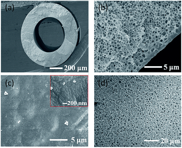
Typical hollow fibre membranes collapse or burst at high pressures, which have a lower pressure resistance than that of flat sheet membranes.8 Application of OSN requires high pressure; therefore, hollow fibre membranes with a high polymer concentration were fabricated with a sponge structure through liquid–liquid phase separation (Fig. 1(a) and (b)) (more details about the fabrication method of polyamide 6 hollow fibre membrane can be found in the Fig S1 and Table S1, ESI†). The hollow fibre membranes for OSN were fabricated with 30 wt% polymer and 70 wt% mixed diluent (DMSO2 and sulfolane). The sulfolane content in the diluent was fixed at 26 wt%. The content of sulfolane in the diluent also plays an important role in forming the skin layer of the membrane.17 When only DMSO2 is used as a diluent without any sulfolane, the resulting membrane is brittle because of the characteristics of DMSO2. DMSO2 cannot be extracted from hollow fibre membrane while spinning and winder process because the melting point of DMSO2 is around 109 °C which is solid state at room temperature as well as solubility is low in water.17 Therefore, sulfolane, which shows good solubility with polymers at high temperatures, was used as the second diluent. However, when the sulfolane content in the diluent is increased, pores are formed on the surface because the compatibility between sulfolane and PEG400 as the bore solution is higher than that between DMSO2 and PEG400. This phenomenon has been well explained in our previous paper.17 When polymer dope solution (polymer A/diluent B) (Fig. S2, ESI†) contacts with solution C (bore solution or quenching bath) in the TIPS process, two factors such as compatibility between polymer A and solution C, and compatibility between diluent B and solution C are important. As shown in Fig. S2,† when the compatibility between polymer A and solution C is higher than that of between diluent B and solution C, polymer is more likely to contact with solution C at the interface and thus dense polymer layer is formed at this interface. On the other hand, the compatibility between diluent B and solution C is higher, more diluent contacts with solution C and the polymer concentration decreases at the interface, which results in the porous structure formation.17
When PEG400 was used as a bore solution, the inner surface of the fabricated hollow fibre membrane was defect free and dense (Fig. 1(b) and (c)). As described above, when the compatibility between the polymer and bore solution is high and that between the diluent and bore solution is low, the polymer becomes close with bore solution and a dense skin layer is formed at the interface.17 In order to reduce the membrane resistance (Rm) of the membrane, out-layers of the membranes were formed as the porous surface (Fig. 1(d)). This porous structure formation is owing to the use of propylene glycol (PG)/water mixture as the quenching bath solution.
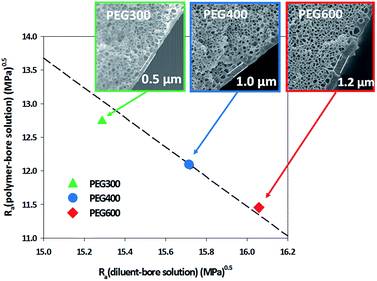
PEG300, PEG400, and PEG600 were used as the bore solution to control the thickness of the skin layer. As shown in Fig. 2, in the bulk of all membranes, interconnected and bicontinuous pore structures were formed. The bulk structure of all membranes did not significantly change when the bore solutions are changed. This is because the bulk structure is determined by the L–L phase separation during cooling. When PEG300 was used as a bore solution, the thickness of the skin layer was about 0.5 μm, and when PEG400 and PEG600 were used, the thickness increased to about 1 and 1.2 μm, respectively. This phenomenon can be explained from the solubility parameter ‘distance’ (Ra) based on the Hansen solubility parameter (Table S2 and Fig. 2, ESI†).17 The Ra value between PEG600 and the polymer is 11.45 MPa0.5, while those between PEG400 and polymer, between PEG300 and polymer were 12.09 MPa0.5 and 12.74 MPa0.5, respectively. On the other hand, the Ra value between PEG600 and the diluent is 16.06 MPa0.5, and those between PEG400 and the diluent, between PEG300 and diluent were 15.72 MPa0.5 and 15.29 MPa0.5, respectively (Table S2, ESI†). This means that the interaction between PEG600 and the polymer is larger than those of PEG400/polymer, PEG300/polymer and the interaction between PEG600 and the diluent is smaller than those of PEG400/diluent and PEG300/diluent. This implies that the polymer is more firmly in contact with PEG600 as a bore solution compared with PEG400 and PEG300 (ESI).17 Therefore, the skin layer of the membrane obtained using PEG600 was thicker than those fabricated using PEG400 and PEG300.
The hollow fibre membranes fabricated were examined for methanol permeance and cobalamin (vitamin B12, VB12) rejection for applicability in OSN (Fig. 3). Methanol is used in this study as the organic solvents because methanol has been used extensively for solvent extraction and organic compound synthesis in pharmaceutical and petroleum industries.1,18–20 In general, dye solutions with different molecular weights, such as rose bengal, brilliant blue, and safranin O, are used for investigating rejection performance. However, structure of most dyes are not spherical, which makes it difficult to determine the pore size.1 In this study, we used VB12 as a marker. VB12 is a metabolism substance required in the human body and is widely used in pharmaceutical industry. Its molecular weight is approximately 1355 g mol−1 and it has a spherical structure and is a neutral molecule. Its Stokes diameter in water is approximately 1.68 nm and is useful for estimating the nanopores of membrane (Fig. S3, ESI†).
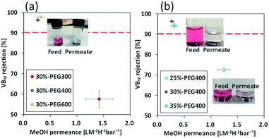
The membrane fabricated using PEG300 showed permeance of 1.42 L m−2 h−1 bar−1 for methanol, while those prepared using PEG400 and PEG600 showed permeances of 0.27 and 0.32 L m−2 h−1 bar−1, respectively (Fig. 3(a)). VB12 rejection shows the opposite relationship to permeance. VB12 rejection of the membrane fabricated using PEG300 was 57.6% in methanol, whereas those of the membrane fabricated using PEG400 and 600 were 96.3% and 97.7%, respectively (Fig. 3(a)). This is because selective skin layer of the membrane fabricated using PEG300 has a thinner layer than those of the membrane fabricated using PEG400 and PEG600 (Fig. 2). From this results, the membrane fabricated using PEG600 showed highest performances in term of methanol permeance and VB12 rejection. However, when the hollow fibre membrane was fabricated using 35 wt% polymer concentration and PEG600 as a bore solution, the methanol was not penetrated from the membrane at 3 bar. Thus, to comparative analysis on the effect of polymer concentration and bore solution, PEG400 was used as a control parameter in this study.
One of the easiest ways to increase the selectivity of a membrane prepared by a one-step process is to increase the polymer concentration.15 To investigate the effect of polymer concentration, polyamide 6 hollow fibre membranes were fabricated using 25, 30 and 35 wt% polyamide 6 dope solution and PEG400 as the bore solution. The methanol permeance of the hollow fibre membrane fabricated using 25 wt% polymer solution was 1.24 L m−2 h−1 bar−1, while those fabricated using 30 and 35 wt% polymer solutions were approximately 0.27 and 0.31 L m−2 h−1 bar−1, respectively. VB12 rejection of the membrane fabricated using 25 wt% polymer solution was 72.7% in methanol, whereas those of the membrane fabricated using 30 and 35 wt% dope solution were 96.3% and 94.2%, respectively (Fig. 3(b)). The thickness of the skin layer on the inner surface is not changed significantly during the increase of the polymer concentration (Fig. S4†). However, when the polymer concentration increased from 25 to 30 wt%, the permeance and VB12 rejection were changed greatly. It can be hypothesized that the skin layer became denser by polymer entanglement at high polymer concentration. Therefore, for the separation of the delicate fine molecular, the skin layer of the polyamide 6 hollow fibre membrane should be controlled by changing the interaction between the dope solution and the bore solution without any post-treatment such as the thin film composite (TFC) or dip-coating method.
Polyamide 6 is very stable to strong aprotic solvents, and was thus fabricated as a membrane by a one-step process without any additional process. The fabricated hollow fibre membranes were observed in a strong organic solvent such as ethanol, DMSO, NMP, DMF, and DMAc for evaluating their durability, and weight loss, tensile strength, and elongation characteristics were evaluated for four months (Fig. S5, ESI†) (more details about the evaluation method for the chemical stability of polyamide 6 hollow fibre membranes can be found in the ESI). As shown in Fig. S5(a),† the weight loss of the membranes immersed in each solvent for four months reduced by only 3.7%, indicating that the polyamide 6 membrane was very stable in all solvents. The physical change of the membranes is also a very important issue for chemical and pharmaceutical industries, in which many organic solvents; in other words, membrane durability is very important in OSN are typically used.4,18,20,21 When a physical change in the membrane such as weight loss occurs in the presence of a kind of solvent, the permeation increases while the selectivity decreases sharply. Eventually, it will lose its function as a membrane. The fabricated polyamide 6 membranes are highly stable in various organic solvents due to that of nature without cross-linking.17
Hollow fibre membranes without any supporter must be able to withstand high pressures by themselves.8,22 Tensile strength and elongation tests were performed to investigate these mechanical properties (Fig. S5(b) and (c)†). The pristine membranes showed a tensile strength of about 9.8 MPa before immersion in the solvents. No significant change was observed in the tensile strength and the elongation after four months.
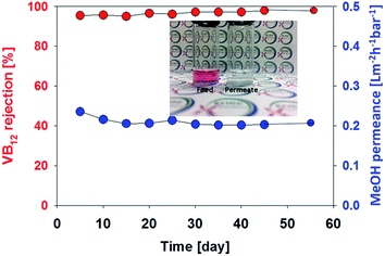
In order to evaluate the hollow fibre membrane (membrane fabricated using PEG400, 30 wt% polymer) durability, long term stability test was conducted using a VB12 methanol solution of 100 ppm at 3 bar over a period of 55 days (Fig. 4). The membrane shows a stable permeance (0.21 L m−2 h−1 bar−1) and very high rejection (>98%) without any decline. This reveals that membrane compaction and degradation were not occurred under the pressure and organic solvent during long term test.
 | ||
| Fig. 4 Long term stability of polyamide 6 hollow fibre membrane in methanol. Test was carried out using a VB12 methanol solution of 100 ppm at 3 bar over a period of 55 days. | ||
In summary, we fabricated OSN hollow fibre membranes through new methods that are different from conventional complex processes such as cross-linking or TFC. The membrane fabricated using PEG300 showed high permeance for methanol, while those prepared using PEG400 and PEG600 showed low permeances by the different interaction at the interfacial layer. In term of effect of polymer concentration, the hollow fibre membrane fabricated using 25 wt% polymer solution showed high permeance, while those fabricated using 30 and 35 wt% polymer solutions showed low permeances. The fabricated membranes showed sufficient permeability and rejection performance for application to OSN. Also, because the fabrication of the newly proposed membrane using the TIPS method involved a green solvent and diluent, we anticipate that it will become a promising technology that will attract the attention of both the industry and researchers in the future.
Conflicts of interest
There are no conflicts to declare.Acknowledgements
We acknowledge Mr Takahiro Ono from Unitika Ltd. for the supply of polyamide 6. This work was supported by Grants-in-Aid from the Special Coordination Funds for Promoting Science and Technology, Creation of Innovation Centers for Advanced Interdisciplinary Research Areas (Innovative Bio-production, Kobe) from the Ministry of Education, Culture, Sports, Science and Technology, Japan.Notes and references
- P. Marchetti, M. F. Jimenez Solomon, G. Szekely and A. G. Livingston, Chem. Rev., 2014, 114, 10735–10806 CrossRef PubMed
.
- D. Kim, O. R. Salazar and S. P. Nunes, Green Chem., 2016, 18, 5151–5159 RSC
.
- G. Szekely, M. F. Jimenez-Solomon, P. Marchetti, J. F. Kim and A. G. Livingston, Green Chem., 2014, 16, 4440–4473 RSC
.
- C. Ursino, S. Simone, L. Donato, S. Santoro, M. P. De Santo, E. Drioli, E. Di Nicolo and A. Figoli, RSC Adv., 2016, 6, 81001–81012 RSC
.
- A. Asadi Tashvigh, L. Luo, T.-S. Chung, M. Weber and C. Maletzko, J. Membr. Sci., 2018, 545, 221–228 CrossRef
.
- J. Aburabie, P. Neelakanda, M. Karunakaran and K.-V. Peinemann, Reactive and Functional Polymers, 2015, 86, 225–232 CrossRef
.
- M. Amirilargani, M. Sadrzadeh, E. J. R. Sudhölter and L. C. P. M. de Smet, Chem. Eng. J., 2016, 289, 562–582 CrossRef
.
- S.-P. Sun, S.-Y. Chan, W. Xing, Y. Wang and T.-S. Chung, ACS Sustainable Chem. Eng., 2015, 3, 3019–3023 CrossRef
.
- S.-P. Sun, S.-Y. Chan and T.-S. Chung, Chem. Eng. Sci., 2015, 129, 232–242 CrossRef
.
- H. Siddique, Y. Bhole, L. G. Peeva and A. G. Livingston, J. Membr. Sci., 2014, 465, 138–150 CrossRef
.
- I. B. Valtcheva, P. Marchetti and A. G. Livingston, J. Membr. Sci., 2015, 493, 568–579 CrossRef
.
- S. Shi-Peng, C. Tai-Shung, L. Kang-Jia and C. Sui-Yung, AIChE J., 2014, 60, 3623–3633 CrossRef
.
- F. Macedonio and E. Drioli, Engineering, 2017, 3, 290–298 CrossRef
.
- H. M. Tham, K. Y. Wang, D. Hua, S. Japip and T.-S. Chung, J. Membr. Sci., 2017, 542, 289–299 CrossRef
.
- H. Matsuyama, S. Rajabzadeh, H. Karkhanechi and S. Jeon, in Comprehensive Membrane Science and Engineering, Elsevier, Oxford, 2nd edn, 2017, pp. 137–189, DOI:10.1016/B978-0-12-409547-2.12244-9
.
- C. Fang, S. Jeon, S. Rajabzadeh, L. Cheng, L. Fang and H. Matsuyama, J. Mater. Chem. A, 2018, 6, 535–547 Search PubMed
.
- S. Jeon, H. Karkhanechi, L.-F. Fang, L. Cheng, T. Ono, R. Nakamura and H. Matsuyama, J. Membr. Sci., 2018, 546, 1–14 CrossRef
.
- J. Imbrogno, L. Rogers, D. A. Thomas and K. F. Jensen, Chem. Commun., 2018, 54, 70–73 RSC
.
- J. F. Kim, G. Szekely, M. Schaepertoens, I. B. Valtcheva, M. F. Jimenez-Solomon and A. G. Livingston, ACS Sustainable Chem. Eng., 2014, 2, 2371–2379 CrossRef
.
- S. So, L. G. Peeva, E. W. Tate, R. J. Leatherbarrow and A. G. Livingston, Chem. Commun., 2010, 46, 2808–2810 RSC
.
- G. Székely, J. Bandarra, W. Heggie, B. Sellergren and F. C. Ferreira, J. Membr. Sci., 2011, 381, 21–33 CrossRef
.
- Y. Feng, M. Weber, C. Maletzko and T.-S. Chung, J. Membr. Sci., 2018, 549, 550–558 CrossRef
.
Footnote |
| † Electronic supplementary information (ESI) available. See DOI: 10.1039/c8ra03328e |
| This journal is © The Royal Society of Chemistry 2018 |


![[thin space (1/6-em)]](https://www.rsc.org/images/entities/char_2009.gif) :
:
