 Open Access Article
Interfacial tension and CO2 diffusion coefficients for a CO2 + water and n-decane system at pressures of 10 to 160 bar†
Nikhil Bagalkot and
Aly A. Hamouda
 *
*
Department of Energy and Petroleum, University of Stavanger, 4036, Norway. E-mail: aly.hamouda@uis.no; nikhil.bagalkot@uis.no
First published on 14th November 2018
Abstract
The objective of this study is to address the influence of different CO2 phases and degrees of CO2 saturation on the interfacial tension and the diffusion of CO2 into a hydrocarbon drop. Axisymmetric drop shape analysis on a pendant drop was used to carry out experiments in a pressure range of 10 to 160 bar and temperatures of 25 °C, 35 °C, and 45 °C, thus covering the gaseous, liquid, and supercritical phases of CO2. A numerical model that estimates the diffusion coefficient of CO2 in the hydrocarbon was developed. The IFT between the carbonated water and the hydrocarbon increases with pressure in the gaseous phase of CO2 and decreases in the liquid and supercritical CO2 phases. Interestingly, when the pressure was increased above 120 bar, the IFT did not change (decrease); this indicates that above this pressure, complete miscibility may not be achieved for this system, as indicated by the stable IFT. From the results, it can be concluded that the maximum IFT, maximum density decrease, and minimum diffusion coefficient occurred at pressures near to and below the phase change pressure of CO2 (64 bar at 25 °C and 74 bar at 35 °C and 45 °C). Both CO2–water–hydrocarbon and CW–hydrocarbon systems show the same trends; however, there were significant differences in the CO2 mass transfer rate and the concentration gradient.
1 Introduction
The mass transfer of gases into liquids and interfacial studies of this transfer are of great importance in numerous fields of science and its applications, such as processes involving oil–water and CO2–liquid fluid systems. The mass transfer of CO2 into hydrocarbons is applicable to the enhanced oil recovery process (EOR). The mass transfer of CO2 and the resulting mechanisms, such as swelling and enhanced mobility of the oil, dictate the degree of oil recovery in CO2-based EOR methods.1,2 Diffusion of CO2 and interfacial phenomena are the mechanisms which control the CO2 mass transfer3 and hence control the swelling and mobility. Additionally, the interfacial tension is of primary importance in the context of multiphase flow in reservoirs, and it is pivotal in controlling miscibility behaviour.4In recent times, due to an increase in the emission of anthropogenic CO2, effort has been made to couple CO2 EOR and CO2 sequestration. However, CO2 EOR for CCS has some drawbacks, such as high cost of transportation, lower storage capacity due to poor sweep efficiency,5 and risk of CO2 leaking back to the surface due to its lower density compared to other reservoir liquids.2,6 Few studies have succeeded in improving the efficiency and safety of the CO2 EOR as a CCS option. Studies7,8 attempted to blend CO2 with solvents such as amino acids, piperazine, water, and diethanolamine (DEA). Laboratory studies2,6 have shown that combining water and CO2 (carbonated water, CW) as an injecting fluid is an efficient option for both oil recovery and CO2 sequestration. From the EOR point of view, carbonated water injection (CWI) enhances the sweep efficiency by reducing the gravity segregation and “fingering” effect that is generally experienced with gas injection and CO2-EOR, hence increasing the incremental oil recovery. Additionally, dissolution of CO2 into water creates carbonated water, which has a higher density compared to native brine (formation water); hence, it sinks to the bottom of the reservoir, reducing the risk of buoyancy-driven leakage.2,6 Molecular diffusion and interfacial tension (liquid/liquid) are vital to assess the rate and distribution of CO2.9
The pendant drop technique is a widely used and effective method for analysing the mass transfer and the interfacial tension between two fluids at elevated pressure and temperature.10 Over time, the pendant drop technique has been developed into an advanced and accurate (±0.05 mN m−2) method called axisymmetric drop shape analysis (ADSA).4,10 Numerous studies have been carried out using the pendant drop technique that are applicable to CO2-based EOR for multiphase systems consisting of CO2–light hydrocarbon,11,12 CO2–crude/heavy oil,13 CO2–brine/water,14–16 water–oil,17 and brine–oil.18 Although these studies have provided critical information, there is a general lack of understanding of (1) the effects of the water layer present between CO2 and the hydrocarbon on the interfacial tension (IFT); (2) the influence of temperature on the IFT; (3) the influence of the phase of CO2 (gas, liquid, or supercritical) on the IFT.
Petroleum reservoirs contain water along with hydrocarbons in their systems; the injected CO2 encounters water before it diffuses into the residual oil. The presence of water dictates and significantly alters the CO2 mass transfer and associated physics, such as IFT. Moreover, most studies on CO2–hydrocarbon and CO2–water–hydrocarbon systems have overlooked the influence of temperature on the IFT; this is mainly due to its unpredictable relationship with temperature. There are discrepancies associated with the IFT vs. temperature relationship; for example,19 reported an inverse relationship of IFT with temperature, while10 reported a direct relationship for CO2–hydrocarbon systems. Further, few studies have collectively investigated the influence of different phases of CO2 (gas, liquid, and supercritical) on the IFT of CO2–hydrocarbon or CO2–water–hydrocarbon systems. The density of the CO2 changes significantly with the phase (gas, liquid, and supercritical), and the density and IFT are related.20 Hence, it is important to study how the IFT is influenced by the different phases of CO2. Additionally, factors such as temperature, pressure, composition, the density of the immiscible fluids, CO2 solubility, and the phase of CO2 influence the interfacial tension.4 Numerous studies have investigated the influences of these factors on IFT with a focus on individual parameters, but few studies have taken these factors into account simultaneously; this would be meaningful because all these parameters are interrelated.
Through experimental, theoretical, and numerical models, the present study attempts to estimate the interfacial tension and effective diffusion coefficient and identify the associated physics for a CO2–water–n-decane system. Axisymmetric drop shape analysis (ADSA) pendant drop experiments have been carried out in a large pressure range of 10 to 160 bar and at a wide range of temperatures (25 °C, 35 °C, and 45 °C). A mathematical model has been developed that uses the experimental inputs to determine the composition, density and viscosity of the pendant drop as a function of time. A theoretical model (Eyring's absolute rate theory approach) using the Gibbs free energy and viscosity of the pendant drop has been presented to elucidate the behaviour of the IFT with temperature. Further, a numerical model with adaptive boundaries has been developed to estimate the diffusion coefficient of CO2 in the hydrocarbon pendant drop. This study makes four major contributions to the existing knowledge on systems involving CO2. First, the experiments were designed to analyse the influence of the degree of carbonation of the water layer between CO2 and the hydrocarbon on critical parameters such as the IFT, diffusion coefficient, and hydrocarbon properties. Second, the experimental pressure range (10 to 160 bar) and temperature range (25 °C to 45 °C) were chosen to study the influence of the phase of CO2 (gas, liquid, or supercritical) on the CO2 diffusion and IFT. Third, the study addresses the inconsistencies in results reported in the literature regarding the relationship between temperature and IFT by relating the experimental IFT and viscosity-dependent Gibbs energy from the developed model. Fourth, the study involves parameters such as the density, viscosity, mass/mole fraction, Gibbs free energy, temperature, pressure, concentration gradient, diffusion coefficient, and phase of CO2. Hence, it is convenient to identify and correlate parameters or physics that are being influenced and influenced by interfacial tension in a CO2–water–hydrocarbon system. Additionally, using the IFT, volume, and CO2 concentration gradient as the parameters, a comparative study has been performed between the CO2–water–hydrocarbon system and a carbonated water–hydrocarbon system.
2 Theory
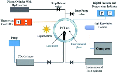
The well-established axisymmetric drop shape analysis (ADSA) technique is employed in the present work. The ADSA method involves a high pressure high temperature isolated cell (PVT cell) in which an axisymmetric pendant drop (drop phase) is created at the end of a capillary tube in a high-pressure see-through cell filled with another fluid (environment phase) (see Fig. 1 for reference). In the present work, n-decane forms the drop phase and water + CO2 or CO2-enriched water (CW) forms the environment phase. Once the hydrocarbon drop (HD) which forms the drop phase and the environmental phase (water) are established, CO2 is injected into the PVT cell at the required pressure and temperature. The CO2 first diffuses and dissolves in the water, carbonising the water; the concentration of CO2 in the water changes from zero to a maximum as the diffusion progresses. Because the solubility of CO2 is greater in the hydrocarbon than in water, the CO2 from the carbonised water diffuses into the hydrocarbon pendant drop. Therefore, the direction of CO2 mass transfer is from the free CO2 phase into the hydrocarbon drop through water. The mass transfer of CO2 and its subsequent dissolution into the hydrocarbon will lead to alterations in the physical properties of the hydrocarbon and in the interfacial tension, which is the focus of this study.2.1 Experimental setup and methodology
Fig. 2A shows a snapshot of the drop phase (HD) and environmental fluid inside the PVT cell. Fig. 2B shows the equivalent spherical HD employed in the numerical analysis (a detailed explanation of the advantages of the spherical drop is presented in Section 3.0). In Fig. 2B, PD and PE represent the physical regions occupied by the hydrocarbon drop phase and the surrounding environmental phase, respectively; r, z, and RD are the radius of the drop (radial coordinates), axial coordinate, and radius of the spherical drop, respectively; and DPVT represents the diameter of the PVT cell.
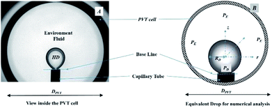 | ||
| Fig. 2 (A) Pendant hydrocarbon drop with surrounding fluid as viewed in the PVT cell. (B) Equivalent surrounded spherical drop for numerical analysis. | ||
In the present work, the following justifications are made. The mass transport across the water–hydrocarbon drop interfaces is diffusive (concentration-driven); this is accomplished by using a HD with a small volume, eliminating density-driven convection.23 Each individual experiment was carried out at a constant temperature, which minimises thermal convention.23 Due to the significantly lower solubility of water in n-decane than in CO2, the mass transfer of water into the hydrocarbon was neglected, and only the mass transfer of CO2 was considered. The mass was calculated from the density at the experimental temperature and pressure to obtain the mass and, hence, the mole fraction of the diffused CO2.24,25 Finally, no chemical reactions transpired during the experiments; therefore, the mechanisms of the changes in the properties are physics-driven and thermodynamically driven processes.
In the experimental procedure, first, the PVT cell was partially filled (20 ml of 25 ml) with deionised water; then, the n-decane pendant drop was created. Then, the CO2 was released into the PVT cell at the experimental pressure, as shown in Fig. 1. The CO2 acted a source, meaning that there was a constant supply of CO2 at the required pressure. Once the CO2 was released into the PVT cell, it first diffused and dissolved in the environmental fluid (water), carbonising it; the CO2 then diffused into the pendant drop. As a result, the volume and shape of the HD changed; this was captured by the camera and later analysed to estimate the IFT and swelling.
2.2 Mathematical model for estimation of the diffusion coefficient
The objective of the model was to estimate the diffusion coefficient of CO2 by determining the concentration of CO2 in the HD. The mathematical model, which was adopted from 11 with some modifications, relies on estimating the concentration of CO2 diffused into the HD. The model employs Fick's second law of diffusion, represented by eqn (1). It can be seen from Fig. 2B that the pendant drop is symmetrical about the z-axis. Hence, it was convenient to use a cylindrical coordinate system (r, θ) rather than a complicated 3D Cartesian coordinate system (x, y, and z) to perform the three-dimensional analysis.
 | (1) |
Eqn (1) along with the boundary and initial conditions was numerically solved to obtain the time and space-dependent concentration of CO2 in the drop. Then, the ratio of the CO2 concentration in the HD (Cavg) as a function of time was computed (eqn (2)). The Cavg (mm3) value gives the total concentration of CO2 diffused in the HD at the required time.
 | (2) |
The mass transfer of CO2 into the HD leads to an increase in the volume (swelling). The magnitude of the volume increase is a function of the amount of CO2 that diffuses into the HD. The parameter Cavg, given in eqn (2), gives the volume of CO2 present in the drop; this can be used to calculate the swelling factor (SF). The swelling factor is the ratio of the volume of the CO2-saturated hydrocarbon (CO2 + hydrocarbon) to the initial volume of the pure hydrocarbon and is represented by eqn (3).11
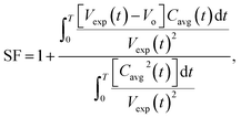 | (3) |
If CO2 + n-decane is assumed to form an ideal mixture, at any instant of time, the summation of the initial volume of HD (Vo) and the increment in the volume of HD due to diffusion of CO2 will equal the total volume of the HD. The increase in volume is represented as the product of Cavg and SF − 1,23 as represented by eqn (4).
| V(t) = Vo + (SF − 1)Cavg(t) | (4) |
An objective function (F) given by ref. 23 uses the difference between the experimental volume (Vexp(t)) and numerical volume (V(t)) of the pendant drop at a given time t. The value of the diffusion coefficient at which the objective function is minimum (Fmin) is the diffusion coefficient of CO2 in the HD. The lower the Fmin, the nearer the numerical result to the experimental result. A detailed process of obtaining the diffusion coefficient can be found in ref. 11.
 | (5) |
The objective function defined in eqn (5) is a function of the numerical V(t) and experimental Vexp(t) volumes. Further, F is a function of Cavg and the SF (eqn (4) and (5)), and Cavg is a function of the diffusion coefficient; this indicates that F = f(D, SF). Hence, D and SF can be used as parameters to obtain the minimum objective function (Fmin). The minimum objective functions (Fmin) for D and SF are the measured CO2 diffusion coefficient and oil-swelling factor, respectively.23
At any instant of time, the volume of the HD (VHD) is a summation of the volume of n-decane (VHC) and the volume of CO2 (VCO2) that has diffused into the HD. The volumes of the HD as a function of time were obtained from the experiment. At the beginning of the experiment (time t = 0), the HD consisted of only hydrocarbon (100% n-decane), which gives VHC. Hence, at a given instant, the volume of CO2 (VCO2) is given by eqn (6).
| VCO2(t) = VHD(t) − VHC | (6) |
Using the volume, the mass/mole fractions of CO2 and n-decane in HD can be obtained; these can be further used to estimate the viscosity and density of the HD. Eqn (7) proposed by ref. 26 gives the viscosity of the CO2 + n-decane mixture. The viscosities obtained from eqn (7) have an accuracy of 1.5% average deviation for the hydrocarbon mixtures and 5% maximum deviation.26
 | (7) |
Eqn (8)27–29 represents the analytical equation for the density of the HD (CO2 + hydrocarbon) using the volume fractions derived from the experiments.
| ρdrop = ((mCO2ρCO2)+(mHCρHC))P,T, | (8) |
2.3 IFT calculations
IFT measurements were carried out using the ADSA system (KRUSS DSA 100). Diffusion of CO2 into the HD alters the density of the HD, which is proportional to the mass of CO2 transferred into the hydrocarbon (volume) (eqn (11)). Therefore, to perform an accurate dynamic measurement of the IFT, the density of the drop with CO2 was input into DSA 100 software to account for the density change. The detailed process of estimating the dynamic IFT can be obtained from ref. 30.2.4 Gibbs energy model
In this section, the Gibbs classical model is used to understand the influence of temperature on the interfacial tension between the HD and the environment fluid. The interfacial energy is directly related to the change in the Gibbs free energy (ΔG). Eyring's absolute rate theory approach gives a relation from which the viscosity of a binary liquid mixture can be estimated from the change in the Gibbs free energy, as given in eqn (9).31 In the present article, the viscosities of both the environment (water + CO2) and HD (CO2 + n-decane) were estimated from eqn (7). The values of the viscosities were then used to calculate the change in the Gibbs free energy (ΔG).
 | (9) |
 | (10) |
As shown in Fig. 1–3, there are two phases, the environmental phase (water + CO2) and drop phase (n-decane + CO2); the interface layer may be assumed to be thin. Hence, the change in the Gibbs free energy for the entire system can be given by eqn (11).
| ΔGS = ΔGE + ΔGHD | (11) |
2.5 Significance of the ranges of pressure and temperature
One of the objectives of this study is to address the influence of the CO2 phase (gas, liquid, or supercritical) on the IFT and mass transfer. Experiments have been carried out for a pressure range of 10 to 160 bar and at three temperatures, 25 °C, 45 °C and 35 °C, for pressures of 10 to 80 bar. For these pressures and temperatures, CO2 is in a gaseous state for P < 64 bar at 25 °C and P < 73 bar at 35 °C and 45 °C; however, for P > 64 bar at 25 °C, CO2 is in a liquid phase. Above P > 73 bar and at 35 °C and 45 °C, CO2 is in the supercritical phase. The experimental pressure and temperature cover the whole spectrum of the CO2 phase diagram. To our knowledge, the whole spectrum of CO2 phases and their effects on the physical properties of these systems has not been addressed in the literature, especially for CO2–water–hydrocarbon and CW–hydrocarbon fluid systems. For simplicity, the analysis of the gaseous phase of CO2 (<64 bar at 25 °C and <73 bar at 35 °C and 45 °C) will be termed low-density CO2 operation, and the analysis of the supercritical/liquid phase of CO2 (>64 bar at 25 °C (liquid) and >73 bar at 35 °C and 45 °C (supercritical)) will be termed high-density CO2 operation.3 Numerical model
A numerical model has been developed to estimate the concentration distribution (spatial and temporal) of CO2 and, hence, the diffusion coefficient in the pendant hydrocarbon drop. For simplicity, a spherical hydrocarbon pendant drop is assumed for the numerical analysis instead of the actual shape of the pendant drop. Fig. 2B shows the equivalent spherical drop surrounded by CO2 used for the numerical analysis. In Fig. 2B, R is the radius of the spherical drop. The experimental radius obtained from the experimental pendant drop volume was used to obtain the surface area, and the radius of the equivalent drop was used for the numerical analysis. The surface area defines the rate of diffusion; hence, it was used as the comparison parameter between the pendant drop (experimental) and spherical drop (numerical). From the comparisons made, an error of 3% to 6% was found depending on the pressure of the system between the experimental and numerical drop surface area.11 Therefore, it is justified to use a spherical drop instead of the actual pendant shape. Further, the assumption of a spherical drop reduces the effort and complexity while simultaneously maintaining minimal error in the estimation of the diffusion coefficient. The method employed in the present study was adopted from ref. 11, with a major change of the inclusion of the dynamic nature of the interface attached to the pendant drop by employing a moving boundary (this is addressed in detail in the following section).3.1 Inclusion of the adaptive interface method in the numerical model
Most of the studies that address the diffusion coefficient have assumed a static nature for the CO2 source–hydrocarbon interface, which is considered to have a constant volume.23,32,33 To our knowledge, no studies have attempted to account for the effects of a dynamic interface for a 3D system. The diffusion coefficient is a function of both experimental (dynamic volume data, Vexp) and numerical (Cavg) data. From eqn (2), it can be noted that the volumetric average of CO2 in the pendant drop (Cavg) is a function of the radius and, hence, of the volume of the drop.In Fig. 2B, RD is the radius of the HD, and the interface is always positioned at the RD. If the volume of the HD increases, the radius will change (RD) and the interface will shift to a new RD; this is only possible if the model has adopted a dynamic boundary (interface). However, if the interface of the drop (boundary) is considered to be static, the interface will not shift its position according to the new RD and will always remain at the initial position of the RD. This will lead to inconsistencies between the numerical and experimental inputs into the model, resulting in errors in the estimation of the diffusion coefficient.
A simple method has been developed in this study to incorporate the dynamic nature of the interface (boundary), and the following steps were carried out.
(i) Initially (t = 0), a fixed number of grids were assigned to N and M number of grids in the r and z directions, respectively.
(ii) The volume of the drop was calculated from eqn (7) at various time intervals.
(iii) For every time interval, the volume at the present time interval (V(t)) was compared with the volume at the previous time interval (V(t − 1)), and the difference between them was obtained (V(t) − V(t − 1)).
(iv) From the difference in the volume (V(t) − V(t − 1)), the increment in the radius of the hydrocarbon pendant drop (Δr) was estimated, which in turn gave the radial distance moved by the interface.
(v) The increment of the radius was then converted to the increment in the number of grids in the r(N) and z(M) directions and was added to the total number of grids in the previous time level (N, M) to obtain the updated number of grids (Nnew, Mnew).
(vi) The new and updated grids were then used to solve the set of equations given in the mathematical model section; this process was repeated for each time step and for every Di of the next input step.
4 Results and discussion
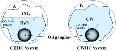
Two fluid–fluid interaction systems (CHHC and CWHC) are addressed in this section. As CO2 dissolves in water, the following reactions may take place:| CO2 + H2O ↔ H2CO3 | (a) |
| H2CO3 ↔ HCO3− + H+ | (b) |
| HCO3− ↔ CO32− + H+ | (c) |
In other words, there are three possible carbonate species; however, the pH of the carbonated water (CO2-saturated water) is within 3 ± 0.5, so the dominant reaction in this work is reaction (a).
4.1 CHHC (CO2–H2O–hydrocarbon) system
 | (12) |
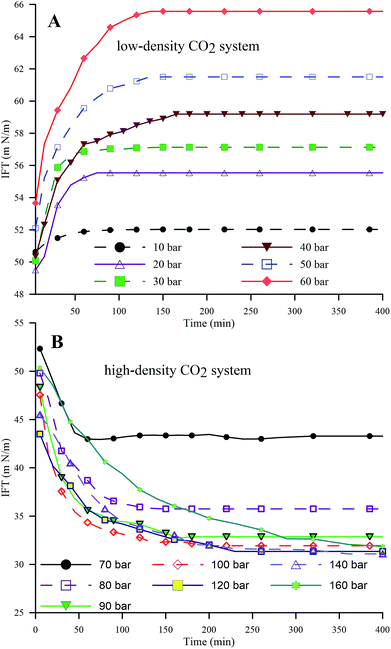 | ||
| Fig. 4 Dynamic IFT of the HD in the pressure ranges of 10 to 60 bar (A) (low-density CO2) and 70 to 160 bar (B) (high-density CO2) at 25 °C. | ||
Fig. 5A and B represent the dynamic density differences between the environmental fluid and the HD for the low-density and high-density CO2 systems, respectively, for the same conditions as in Fig. 4. In Fig. 5A (≤60 bar), CO2 is in a gaseous phase. Under these conditions, the diffusion of the gaseous CO2 into the hydrocarbon decreases the density of the n-decane (drop phase),36 whereas the dissolution of CO2 into water (environmental phase) increases its density.37 Thus, the density contrast between the HD and the environmental fluid increases with the CO2 mass transfer, as observed in Fig. 5A, leading to an increase in IFT (as shown in Fig. 4A). The opposite is true for high-density CO2; as shown in Fig. 5B, there is a small variation in the density with pressure, i.e. a small density difference between the environment and the HD. Therefore, lower IFT is correlated with higher pressure (>70 bar), as observed in Fig. 4B. Further, by observing the data presented in Fig. 4B, it can be seen that the IFT variations fall into two clusters. In the first cluster, the IFT reaches equilibrium more rapidly and has a higher final equilibrium IFT. In the second cluster, the IFT takes more time to reach equilibrium and the behaviour of the IFT with time is similar irrespective of whether the pressure and equilibrium IFT fall in similar value ranges. From this, the 70 and 80 bar pressures belong to the first cluster and the remaining pressures (90 to 160 bar) belong to the second cluster. The closeness of 70 bar to the phase change pressure (64 bar at 25 °C) and the similar densities of CO2 and n-decane may be the reason for this behaviour of the IFT with time at 70 bar.
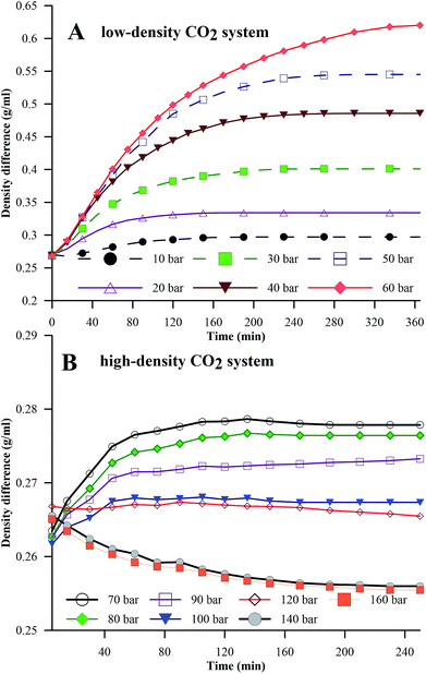 | ||
| Fig. 5 Density differences between the HD and the environment for the pressure ranges of 0 to 60 bar (A) (low-density CO2) and 70 to 160 bar (B) (high-density CO2) at 25 °C. | ||
From the above discussion, the density differences may, in general, offer an explanation for the inverse trend of IFT with pressure; however, density values were used in the IFT estimations, and independent physics may not provide an explanation for this trend. Hence, an attempt has been made to explain the observations in Fig. 4 through kinetics. Interfacial tension is a function of the Gibbs free energy; the lower the Gibbs free energy, the lower the IFT.38 In the simplest form, the Gibbs free energy can be represented as in eqn (13).
| G = H − TS, | (13) |
Fig. 6 extends this work to compare the effects of pressure on the equilibrium IFT for three temperatures (25 °C, 35 °C and 45 °C). Fig. 6 shows the IFT data for the water–n-decane system obtained from ref. 18 (represented by a red dashed curve). It can be observed that at isothermal conditions, the IFT at lower pressure (low-density CO2 system) increases with pressure, while the IFT decreases with pressure for pressures in the high-density CO2 region, as observed with the dynamic IFT. At 35 °C, the pendant drop experiments were carried out up to 70 bar because above 70 bar, repeatability could not be achieved due to the lower pixel gradient between the drop and the environment phase. The CO2 solubility in both water and n-decane increases with increasing pressure; this leads to enhanced mass transfer of CO2 into the HD, eventually leading to a decrease in the density of the HD and an increment in the density gradient across the interface. Therefore, the equilibrium IFT increases with pressure, as observed for the experiments involving low-density CO2. This theory can be used to explain the drastic decrease in the equilibrium IFT for the high-density CO2 region. The density difference is low (Fig. 5B) for the high density CO2 region; this leads to an observed decrease in the IFT (Fig. 6). It can be observed from Fig. 6 that at high pressures (>120 bar), the difference in the IFT between 25 °C and 45 °C decreases and the IFT tends to remain constant. A similar observation was made by,39 where for a supercritical CO2–water system, they observed a small difference in IFT between 26.8 °C (300 K) and 76.85 °C (350 K).
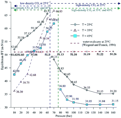 | ||
| Fig. 6 Equilibrium IFT between the HD (CO2 + n-decane) and the surrounding water + CO2 for a pressure range of 10 to 160 bar at 25 °C and 45 °C and a range of 10 to 70 bar at 35 °C. | ||
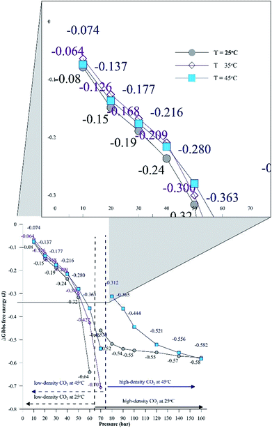
Additionally, Fig. 6 depicts the influence of temperature on the IFT between the HD. The variation of IFT with pressure is similar for all temperatures. In the discussion of Fig. 6, it was shown that the equilibrium IFT for various pressures at isothermal conditions was related to the density difference across the interface. The theory that the density difference is proportional to IFT applies well at isothermal conditions; however, it falters when the temperature is varied at isobaric conditions. It can be observed from Fig. 6 that up to 30 bar, the IFT at 35 °C is lower than that at 45 °C. Above 30 bar (40 to 60 bar), the IFT at 35 °C increases and the IFT vs. temperature returns to normal behaviour, with IFT being maximum for 25 °C, minimum for 45 °C and intermediate for 35 °C. Similar observations have been made in a few studies40,41 for different systems. This observation also deviates from both the CO2–n-decane system11 and H2O–n-decane system,17 where at isobaric conditions, the IFT decreases as the temperature increases. The reason for the observed behaviour of IFT at 35 °C may be the nearness of 35 °C to the critical temperature (31.1 °C) of CO2; hence, it is possible that the entropy of CO2 will be high. Higher entropy (S) will decrease the Gibbs free energy (eqn (13)) and eventually decrease the IFT. To check this hypothesis, the Gibbs free energies (change) obtained from the viscosity of the HD (eqn (10)) have been plotted in Fig. 7 at experimental conditions. In Fig. 7, the section consisting of pressures from 10 to 50 bar has been magnified; it can be observed that for the pressure range of 10 to 40 bar, ΔG is the lowest at 35 °C, higher at 45 °C, and reaches the maximum at 25 °C. Above 40 bar, the ΔG at 35 °C is intermediate between those at 25 °C (maximum) and 45 °C (minimum). Hence, from the observations in Fig. 7, it can be said that up to a certain pressure, the influence of the increase in entropy (decrease in ΔG) due to the temperature increase is greater than the influence of the difference in density. This explains the behaviour of the IFT vs. pressure in Fig. 6 at 35 °C.
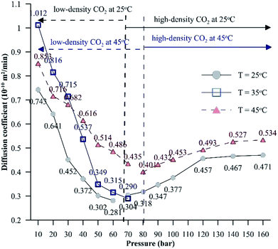 | ||
| Fig. 8 Effective diffusion coefficients of CO2 in the HD for a pressure range of 10 to 160 bar at different temperatures. | ||
Unlike for low-density CO2 systems, for high-density CO2 systems, the diffusion coefficient shows an increasing trend with pressure. At isothermal conditions, due to higher intermolecular forces, the enthalpy energy and, hence, the Gibbs free energy will be lower for liquids compared to gases. Hence, the interfacial tension associated with systems involving liquids (high-density CO2 systems) will be lower compared to that associated with systems involving gases (low-density CO2 systems), which will assist the mass transfer of CO2. Further, as the temperature increases, the entropy energy (TS) increases. The dissolution of CO2 in the hydrocarbon is exothermic in nature; for exothermic reactions, the enthalpy change has a negative value. Therefore, the change in Gibbs energy (ΔH − ΔTS) will be negative, resulting in a higher diffusion coefficient at higher temperatures. The CO2 solubility in water shows signs of reaching a constant value or increases by a small magnitude as the pressure is increased beyond 120 bar at both 25 °C and 45 °C. This further explains why the diffusion coefficient of CO2 reaches a constant value or increases by a small magnitude with increasing pressure.
4.2 Comparison of the CHHC (CO2–H2O–hydrocarbon) and CWHC (CW–hydrocarbon) systems
Fig. 9A shows the differences in the concentration of CO2 between the HD and the environment fluid for both the CWHC and CHHC systems as a function of time for 20, 40, 70, and 100 bar at 25 °C. For the CWHC system, the water surrounding the HD is enriched with CO2 (CW), while in the CHHC system, the concentration of CO2 varies from zero to a maximum. This difference in the CO2 concentration in the water surrounding the HD has a major impact on the CO2 concentration gradient and, hence, the mass transfer of CO2 into the HD. The concentration difference profiles for the CWHC and CHHC systems are contrary to each other (Fig. 9A); for the CWHC system, the concentration difference changes from the maximum to equilibrium as the diffusion progresses, while for the CHHC system, it changes from zero to equilibrium. Hence, during the start of the CO2 diffusion, the concentration gradient for the CWHC system is greater than that of the CHHC system, which may lead to more rapid mass transfer of CO2 for the CWHC system compared to the CHHC system. Due to this, the rate of the increase in volume would be more rapid for the HD surrounded by CW (CWHC) than for the HD surrounded by water and CO2 (CHHC system), as can be seen in Fig. 9B. However, it can observed in Fig. 9A that for the CWHC system, the concentration difference soon reaches a constant value, indicating a possible decrease in the rate of CO2 mass transfer and, hence, the observed change in the slope of the evolution of the volume (Fig. 9B). On the other hand, the concentration difference for the CHHC system increases with time and reaches a constant volume later, resulting in the prolonged lower but steadily increasing volume (Fig. 9B). Further, the higher concentration gradient may also explain the observed faster attainment of equilibrium (CO2 saturation) by the HD for the CWHC system compared to the CHHC system, as shown in Fig. 9B. It can be observed in Fig. 9B for the low-density CO2 system (40 bar) that although the evolution of the volume is different, the equilibrium volumes are similar for the CWHC and CHHC systems. However, for high-density CO2 operation (Figure 9B, 100 bar), the equilibrium volume of the CWHC system is greater than that of the CHHC system.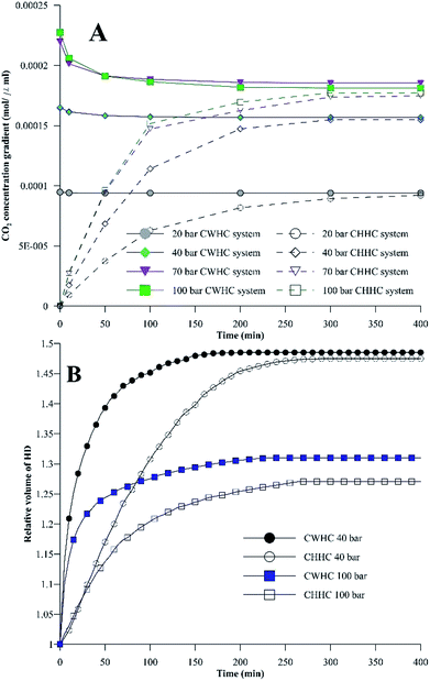 | ||
| Fig. 9 (A) Concentration of CO2 between the HD (n-decane) and the surrounding environment for the CWHC and CHHC systems. (B) Relative volumes of the HD for the CWHC and CHHC systems. | ||
Fig. 10 compares the IFT values for the CHHC (CO2–H2O–n-decane) and CWHC (CW–n-decane) systems at 25 °C for a pressure range of 10 to 160 bar. It can be observed that the variations of IFT with pressure are similar for the CHHC and CWHC systems. Hence, the explanations provided in sections 4.1.1 and 4.1.2 hold true for the CWHC system. However, it can be observed from Fig. 10 that the IFT is lower for the CWHC system than for the CHHC system at all experimental pressures. For low-density operation, the IFT of the CWHC system decreases by approximately 17% at 10 bar to 3% at 60 bar. Meanwhile, for high-density operation, an average 6% decrease in the IFT was observed for the CWHC system compared to the CHHC system. Overall, it can be said that the decrease in the equilibrium IFT by CWHC is insignificant, especially at high pressures. Although small, the decrease in the IFT for the CWHC system compared to the CHHC system can be explained by the differences in CO2 concentration presented in Fig. 9A. Even though the concentration difference of CO2 is higher for the CWHC system compared to the CHHC system, it can be observed (Fig. 9A) that for the CWHC system, the concentration difference of CO2 reaches a constant substantially earlier (around 120 to 250 min) than that of the CHHC system (after 300 min). Hence, there may be a slower but higher mass transfer of CO2 into the HD for the CHHC system compared to the CWHC system; this would alter the overall density difference across the interface, resulting in a marginally higher IFT for the CHHC system. Further, it can observed from Fig. 9B that for the CWHC system, the increase in the volume of the HD occurs mainly during the initial part and reaches a plateau rapidly. This indicates that mass transfer mainly occurs during the initial phase of CO2 diffusion, in contrast with the CHHC system, where both the volume (Fig. 9B) and concentration difference (Fig. 9A) change gradually and linearly compared to those of the CWHC system.
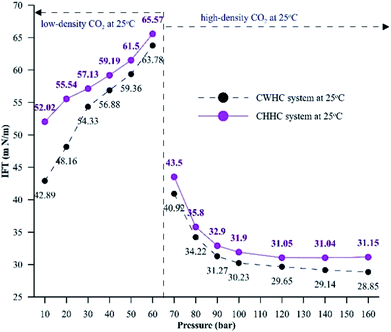 | ||
| Fig. 10 Equilibrium IFT values for CHHC and CWHC system at 25 °C for a pressure range of 10 to 160 bar. | ||
5 Conclusions
The present work, through experimental, mathematical, and numerical studies, addresses the fundamental aspects of interfacial tension and its associated physics in a CO2–H2O–decane system and compares them with those in a CW–decane system. The following conclusions were made from the analysis.The presence of a water layer between CO2 and the hydrocarbon leads to unique behaviour which is unlike that of CO2–hydrocarbon or water–hydrocarbon systems. For gaseous CO2 operation, the IFT increases exponentially with pressure, which is opposite to that observed in a CO2–hydrocarbon system. Compared to the water–n-decane system, the dissolution of CO2 in water and the hydrocarbon increases the IFT for low-density operation and decreases the IFT for high-density operation. The dissolution of CO2 into the water surrounding the hydrocarbon alters the density difference across the interface, leading to the observed behaviour. Although the presence of a water layer increased the IFT of the system, it was successful in increasing the swelling compared to the CO2–hydrocarbon system.
The phase of CO2 has a significant effect on IFT; the IFT behaviour with pressure reverses when the phase of CO2 changes. When gaseous CO2 is in operation (low-density), the IFT increases exponentially with increasing pressure. However, as the operation shifts to supercritical and liquid CO2 (high-density), the IFT decreases with increasing pressure. The changes in CO2 solubility with pressure and the consequent alterations to the density are credited for this behaviour. Further, the phase of CO2 was also a major factor in the variations of the density, diffusion coefficient, and concentration gradient. Each of these parameters experienced a reversal in its behaviour with pressure as the phase of CO2 changed. The maximum density decrease of the hydrocarbon, maximum IFT, and minimum diffusion coefficient were obtained at pressures near and below the phase change pressure of CO2.
The IFT for various pressures at 25 °C was found to be directly proportional to the density difference. This theory applies well to isothermal conditions; however, it falters when the temperature is varied at isobaric conditions. At isobaric conditions, for low-pressure operation, the IFT at 35 °C is lower than at 45 °C; as the pressure increases, the IFT at 35 °C increases and is between those at 25 °C and 45 °C. As indicated by the Gibbs energy model, at 35 °C (close to the critical temperature of 31.1 °C), the system entropy is high; hence, the Gibbs free energy and IFT decrease.
Although the IFT of the CO2–water–hydrocarbon and CW–hydrocarbon systems has the same trends, there is a significant difference in the concentration gradient of CO2 across the interface; hence, the IFT and molecular diffusion are different.
Conflicts of interest
There is no conflict of interest to declare.References
- M. S. A. Perera, R. P. Gamage, T. D. Rathnaweera, A. S. Ranathunga, A. Koay and X. Choi, Energies, 2016, 9, 481 CrossRef.
- M. Riazi, M. Sohrabi and M. Jamiolahmady, Transp. Porous Media, 2011, 86, 73–86 CrossRef CAS.
- B. Wen, C. Sun, B. Bai, E. Y. Gatapova and O. A. Kabov, PCCP, 2017, 19, 14606–14614 RSC.
- M. Ghorbani and A. H. Mohammadi, J. Mol. Liq., 2017, 227, 318–323 CrossRef CAS.
- M. Riazi, M. Sohrabi, M. Jamiolahmady and S. Ireland, Oil recovery improvement using CO2-enriched water injection, EUROPEC/EAGE Conference and Exhibition, Society of Petroleum Engineers, 2009, DOI:10.2118/121170-MS.
- N. I. Kechut, M. Sohrabi and M. Jamiolahmady, Experimental and numerical evaluation of carbonated water injection (CWI) for improved oil recovery and CO2 storage, SPE EUROPEC/EAGE Annual Conference and Exhibition, Society of Petroleum Engineers, 2011, DOI:10.2118/143005-MS.
- Z. Zhang, J. Nat. Gas Sci. Eng., 2016, 31, 589–595 CrossRef CAS.
- Z. Zhang, Y. Li, W. Zhang, J. Wang, M. R. Soltanian and A. G. Olabi, Renewable Sustainable Energy Rev., 2018, 98, 179–188 CrossRef CAS.
- L. Jiang, M. Yu, B. Wu, T. Suekane, W. Li and Y. Song, RSC Adv., 2016, 6, 114320–114328 RSC.
- D. Yang, P. Tontiwachwuthikul and Y. Gu, J. Chem. Eng. Data, 2005, 50, 1242–1249 CrossRef CAS.
- N. Bagalkot and A. A. Hamouda, Ind. Eng. Chem. Res., 2017, 56, 2359–2374 CrossRef CAS.
- J. J. Hsu, N. Nagarajan and R. Robinson Jr, J. Chem. Eng. Data, 1985, 30, 485–491 CrossRef CAS.
- D. Yang and Y. Gu, Ind. Eng. Chem. Res., 2008, 47, 5447–5455 CrossRef CAS.
- S. Banerjee, E. Hassenklöver, J. M. Kleijn, M. A. Cohen Stuart and F. A. Leermakers, J. Phys. Chem. B, 2013, 117, 8524–8535 CrossRef CAS PubMed.
- A. Shariat, R. G. Moore, S. A. Mehta, K. C. Van Fraassen, K. E. Newsham and J. A. Rushing, Laboratory measurements of CO2-H2O interfacial tension at HP/HT conditions: Implications for CO2 sequestration in deep aquifers, Carbon Management Technology Conference, 2012, DOI:10.7122/150010-MS.
- B.-Y. Cai, J.-T. Yang and T.-M. Guo, J. Chem. Eng. Data, 1996, 41, 493–496 CrossRef CAS.
- G. Wiegand and E. Franck, Ber. Bunsenges. Phys. Chem., 1994, 98, 809–817 CrossRef CAS.
- F. Moeini, A. Hemmati-Sarapardeh, M.-H. Ghazanfari, M. Masihi and S. Ayatollahi, Fluid Phase Equilib., 2014, 375, 191–200 CrossRef CAS.
- D. Mackay and K. Hossain, Can. J. Chem. Eng., 1982, 60, 546–550 CrossRef CAS.
- B. Honarvar, A. Azdarpour, M. Karimi, A. Rahimi, M. Afkhami Karaei, H. Hamidi, J. Ing and E. Mohammadian, Energy Fuels, 2017, 31, 2740–2748 CrossRef CAS.
- P. Linstrom and W. Mallard, J. Chem. Eng. Data, 2001, 46, 1059–1063 CrossRef CAS.
- Y.-B. Chang, B. K. Coats and J. S. Nolen, A compositional model for CO2 floods including CO2 solubility in water, Paper SPE 35164, SPE Permian Basin Oil and Gas Recovery Conference, Midland, Texas, USA, March, 1996, pp. 27–29, DOI:10.7122/150010-MS.
- C. Yang and Y. Gu, Ind. Eng. Chem. Res., 2005, 44, 4474–4483 CrossRef CAS.
- M. Sohrabi, M. Riazi, M. Jamiolahmady, S. Ireland and C. Brown, Mechanisms of oil recovery by carbonated water injection, SCA annual meeting, 2009 (International Symposium of the Society of Core Analysts), Noordwijk, The Netherlands, 27–30 September, 2009, Article Number: SCA2009-26, p. 12 Search PubMed.
- M. Riazi, M. Jamiolahmady and M. Sohrabi, J. Pet. Sci. Eng., 2011, 75, 312–326 CrossRef CAS.
- F. Herning and L. Zipperer, Gas Wasser, 1936, 79, 69 Search PubMed.
- M. McBride-Wright, G. C. Maitland and J. M. Trusler, J. Chem. Eng. Data, 2014, 60, 171–180 CrossRef.
- M. E. Kandil, N. M. Al-Saifi and A. S. Sultan, Int. J. Greenhouse Gas Control, 2016, 53, 198–206 CrossRef CAS.
- J. Zambrano, F. V. Gómez-Soto, D. Lozano-Martín, M. C. Martín and J. J. Segovia, J. Supercrit. Fluids, 2016, 110, 103–109 CrossRef CAS.
- N. Bagalkot, A. A. Hamouda and O. M. Isdahl, MethodsX, 2018, 676–683 CrossRef PubMed.
- R. J. Martins, M. J. d. M. Cardoso and O. E. Barcia, Ind. Eng. Chem. Res., 2000, 39, 849–854 CrossRef CAS.
- N. Bagalkot and A. A. Hamouda, Ind. Eng. Chem. Res., 2017, 56, 2359–2374 CrossRef CAS.
- C. Yang and Y. Gu, Fluid Phase Equilib., 2006, 243, 64–73 CrossRef CAS.
- C. E. Stauffer, J. Phys. Chem., 1965, 69, 1933–1938 CrossRef CAS.
- E. Y. Arashiro and N. R. Demarquette, Mater. Res., 1999, 2, 23–32 CrossRef CAS.
- J. S. Miller and R. A. Jones, SPE/DOE Enhanced Oil Recovery Symposium, Tulsa, USA, 1981 Search PubMed.
- M. Sohrabi, M. Riazi, M. Jamiolahmady, N. I. Kechut, S. Ireland and G. Robertson, Energy Procedia, 2011, 4, 2192–2199 CrossRef CAS.
- B. Honarvar, A. Azdarpour, M. Karimi, A. Rahimi, M. Afkhami Karaei, H. Hamidi, J. Ing and E. Mohammadian, Energy Fuels, 2017, 31, 2740–2748 CrossRef CAS.
- S. Iglauer, M. Mathew and F. Bresme, J. Colloid Interface Sci., 2012, 386, 405–414 CrossRef CAS PubMed.
- W. Karnanda, M. Benzagouta, A. AlQuraishi and M. Amro, Arabian J. Geosci., 2012, 1–10 Search PubMed.
- A. Zolghadr, M. Escrochi and S. Ayatollahi, J. Chem. Eng. Data, 2013, 58, 1168–1175 CrossRef CAS.
- M. Jamialahmadi, M. Emadi and H. Müller-Steinhagen, J. Pet. Sci. Eng., 2006, 53, 47–60 CrossRef CAS.
- A. Georgiadis, G. Maitland, J. M. Trusler and A. Bismarck, J. Chem. Eng. Data, 2010, 55, 4168–4175 CrossRef CAS.
Footnote |
| † Electronic supplementary information (ESI) available. See DOI: 10.1039/c8ra03690j |
| This journal is © The Royal Society of Chemistry 2018 |

