 Open Access Article
Evaluation of thin film fuel cells with Zr-rich BaZrxCe0.8−xY0.2O3−δ electrolytes (x ≥ 0.4) fabricated by a single-step reactive sintering method
Seongwoo Jeonga,
Taisei Kobayashia,
Kosuke Kurodaa,
Hyuna Kwonb,
Chunyu Zhuc,
Hiroki Habazakic and
Yoshitaka Aoki *c
*c
aGraduate School of Chemical Sciences and Engineering, Hokkaido University, N13W8 Kita-ku, Sapporo, 060-8628 Japan
bDepartment of Energy Resources Engineering, College of Engineering, Seoul National University, 1 Gwanak-ro, Gwanak-gu, Seoul 08826, Korea
cFaculty of Engineering, Hokkaido University, N13W8 Kita-ku, Sapporo, 060-8626 Japan. E-mail: y-aoki@eng.hokudai.ac.jp; Tel: +81-11-706-6752
First published on 23rd July 2018
Abstract
This paper reports a survey of power generation characteristics of anode-supported thin film fuel cells with Zr-rich BaZrxCe0.8−xY0.2O3−δ (x = 0.4, 0.6, 0.7, and 0.8) proton-conducting electrolytes, which were fabricated by single step co-firing with Zn(NO3)2 additives at a relatively low temperature (1400 °C). The grain sizes significantly increased to several μm for x = 0.4 and 0.6, whereas the grain sizes remained in the sub-μm ranges for x = 0.7 and 0.8, which resulted in large gaps of the fuel cell performances at x over and below 0.6. The cells for x = 0.4 and 0.6 exhibited efficient power generation, yielding peak powers of 279 and 336 mW cm−2 at 600 °C, respectively, which were higher than those of the corresponding cells previously reported. However, the performances abruptly deteriorated with the increasing x to more than 0.7 because the electrolyte films were highly resistive due to the coarse-grained microstructures. Impedance spectroscopy for the dense sintered BaZrxCe0.8−xY0.2O3−δ discs confirmed that the total proton conductivity of BaZr0.6Ce0.2Y0.2O3−δ was higher than that of BaZr0.4Ce0.4Y0.2O3−δ at temperatures above 500 °C despite relatively small grain sizes. In addition, BaZr0.6Ce0.2Y0.2O3−δ cells could gain a stable current throughout a continuous run for a few days under CO2-containing fuel supply, which was due to high fraction of thermodynamically stable BaZrO3 matrices. It was demonstrated that BaZr0.6Ce0.2Y0.2O3−δ is a promising electrolyte for proton-conducting ceramic fuel cells with excellent proton conductivity and CO2 tolerance at intermediate temperatures.
1. Introduction
Solid oxide fuel cells (SOFCs) have attracted much attention because of their fuel flexibility, high efficiency, and lack of requirement of expensive noble metal catalysts;1–3 however, their high operating temperature causes high fabrication and operation cost and durability issues,4 which consequently limit their application and commercialization. Hence, lowering the operating temperature to intermediate temperatures (IT), i.e., 400–700 °C is important for further applications.High temperature proton conductors can decrease the operating temperature, because they have lower activation energy (0.3–0.6 eV) for ionic conduction than typical oxide-ion conductors such as Zr1.8Y0.2O3 (0.8 eV).5 Materials including BaCe0.9Y0.1O3 and BaZr0.8Y0.2O3 possess higher conductivities than Zr1.8Y0.2O3 at temperatures below 700 °C.6 Therefore, protonic ceramic fuel cells (PCFCs) are promising for operations at IT. Although BaCeO3-based oxides display excellent proton conductivity,7 they are thermodynamically unstable in a CO2-containing atmosphere below 800 °C, resulting in their decomposition to BaCO3 and CeO2.8 In contrast, BaZrO3 is thermodynamically stable in a CO2-rich atmosphere; thus, the partial replacement of Ce with Zr can improve the stability in a CO2-rich atmosphere.9,10 Solid solutions, i.e., BaCe1−x−yZrxMyO3 (M = Y, Gd, etc.) tend to be more tolerant to CO2 with the increasing Zr contents9,10 and thus, Zr-rich BaCe1−x−yZrxMyO3 is desirable as a practical electrolyte for IT-PCFCs. Meanwhile, the fuel cell performances are still limited because the solid solutions tend to show poor sinterability with increasing Zr contents due to high refractory nature of BaZrO3 moieties, and their coarse-grained microstructures have large grain-boundary resistances of electrolytes.9,10 Normally, Zr-rich phases require sintering temperatures over 1600 °C (ref. 11) for sufficient grain growth, but such high temperature sintering causes BaO evaporation and undesired reaction at the interface between the electrolyte and cermet anodes, which significantly increases electrolyte resistances of fuel cells.12,13 Hence, it is necessary to fabricate highly efficient anode-supported cells with large-grained electrolyte films using high Zr-content BaCe1−x−yZrxMyO3 (1 − x − y < x) under moderate sintering conditions.
In many scientific studies, wet chemical processes, such as co-precipitation and combustion methods, were employed to prepare fine green powders of BaZrxCe0.8−xY0.2O3, whereas such powders did not lead to highly dense ceramics with more than 90% relative density by sintering at temperatures below 1500 °C, especially for x > 0.4.14 Recently, Duan et al. developed a significantly simplified and cost-effective solid-state reactive sintering (SSRS) method to fabricate anode-supported thin film electrolyte PCFC with BaZr0.1Ce0.7Y0.1Yb0.1O3 (BZCYYb).15 In the SSRS process, phase formation, densification, and grain growth were conducted at a single high-temperature sintering step, and the resultant electrolyte films were significantly densified despite lower (200–400 °C) sintering temperatures compared to the observations of the conventional process.16 The resultant cells could conduct efficient power generation even at 500 °C.15 In this study, we successfully fabricated anode-support thin film fuel cells based on high Zr-content BaZrxCe0.8−xY0.2O3 (x = 0.4, 0.6, 0.7, and 0.8) electrolytes (∼30 μm thickness) by modifying the SSRS method with a single sintering step at around 1400 °C. BaZr0.6Ce0.2Y0.2O3-based cells achieved the highest power output among the four studied cells, which was due to the superior proton conductivity at elevated temperatures; they were also highly tolerant to CO2 due to the relatively high fraction of the thermodynamically stable zirconates, which demonstrated that BaZr0.6Ce0.2Y0.2O3 is a promising electrolyte of intermediate temperature PCFC.
2. Experimental details
2.1 Fabrication of thin film fuel cells with porous anode supports
The anode-supported cells were fabricated by solid-state reactive sintering (SSRS) of green pellets with alternative Zn(NO3)2 sintering aids instead of commonly used NiO aids.15,18,19 The fabrication process is schematically represented in Fig. 1. Precursor powders of BaZrxCe0.8−xY0.2O3−δ (x = 0.4, 0.6, 0.7, and 0.8) were prepared by mixing stoichiometric amounts of starting materials: BaCO3 (High Purity Chemicals, 99.95%), CeO2 (High Purity Chemicals, 99.99%), ZrO2 (High Purity Chemicals, 98%), and Y2O3 (High Purity Chemicals, 99.99%) with addition of 3.56 wt% of Zn(NO3)2·6H2O (Wako chemicals, 99.9%) as a sintering aid. The mixtures were ball-milled in ethanol for 24 h and subsequently dried at 80 °C; thus, precursor powders of BaZrxCe0.8−xY0.2O3−δ (denoted as Pre-1 hereafter) were obtained. For Ni/BaZrxCe0.8−xY0.2O3−δ anode supports, Pre-1 and NiO were blended at a weight ratio of 40![[thin space (1/6-em)]](https://www.rsc.org/images/entities/char_2009.gif) :
:![[thin space (1/6-em)]](https://www.rsc.org/images/entities/char_2009.gif) 60 in ethanol and ball-milled for 48 h. The obtained mixed powders were uniaxially pressed into green pellets (12 mm ϕ, 1.2 mm d) under 20 MPa and subsequently pressed under a hydrostatic pressure of 100 MPa in an isostatic press. The precursor layers of electrolyte films were spin-coated on the green pellets by using a MISAKA 1H-D7 spin-coater. The sols were prepared by dispersing Pre-1 in a solution containing dispersant (20 wt% polyethyleneimine (Mw 28
60 in ethanol and ball-milled for 48 h. The obtained mixed powders were uniaxially pressed into green pellets (12 mm ϕ, 1.2 mm d) under 20 MPa and subsequently pressed under a hydrostatic pressure of 100 MPa in an isostatic press. The precursor layers of electrolyte films were spin-coated on the green pellets by using a MISAKA 1H-D7 spin-coater. The sols were prepared by dispersing Pre-1 in a solution containing dispersant (20 wt% polyethyleneimine (Mw 28![[thin space (1/6-em)]](https://www.rsc.org/images/entities/char_2009.gif) 000) dissolved in α-terpineol) and binder (5 wt% surfactant dissolved in α-terpineol) at a weight ratio of 10
000) dissolved in α-terpineol) and binder (5 wt% surfactant dissolved in α-terpineol) at a weight ratio of 10![[thin space (1/6-em)]](https://www.rsc.org/images/entities/char_2009.gif) :
:![[thin space (1/6-em)]](https://www.rsc.org/images/entities/char_2009.gif) 3
3![[thin space (1/6-em)]](https://www.rsc.org/images/entities/char_2009.gif) :
:![[thin space (1/6-em)]](https://www.rsc.org/images/entities/char_2009.gif) 1, and they were spin-coated on the surfaces of the green pellets at 3000 rpm for 40 s. After spin coating, the pellets were dried at room temperature and co-fired at 1400 °C for 8 h, 12 h, 12 h, and 18 h for x = 0.4, 0.6, 0.7, and 0.8, respectively, in air. The pellets were highly densified by sintering, which resulted in a compact ceramic disc with ca. 9 mm ϕ × 1 mm d.
1, and they were spin-coated on the surfaces of the green pellets at 3000 rpm for 40 s. After spin coating, the pellets were dried at room temperature and co-fired at 1400 °C for 8 h, 12 h, 12 h, and 18 h for x = 0.4, 0.6, 0.7, and 0.8, respectively, in air. The pellets were highly densified by sintering, which resulted in a compact ceramic disc with ca. 9 mm ϕ × 1 mm d.
The back sections of the sintered discs were polished with 1000 SiC abrasive sandpapers and then, Pt paste was applied as a current collector attached with a gold wire (0.1 mm ϕ). Finally, La0.6Sr0.4Co0.2Fe0.8O3−δ (LSCF) button electrode (5 mm ϕ) was deposited on the other side as a porous cathode by screen-printing with a commercial LSCF paste (Fuelcellmaterials) and post-annealing at 700 °C. A Pt mesh was used as a current collector of the cathode.
Bulk ceramics for conductivity measurements of BaZrxCe0.8−xY0.2O3−δ (x = 0.4 and 0.6) were prepared by a process similar to the SSRS process. Pre-1 powders were uniaxially pressed into green pellets (12 mm ϕ, 1.2 mm d) under 20 MPa and subsequently pressed under a hydrostatic pressure of 100 MPa in an isostatic press. The pellets, thus prepared, were reactive-sintered at 1400 °C for 8 or 12 h in air. Both faces of the sintered discs were polished by an SIC paper and then, Pt paste was applied as a current collector.
The phase purity was checked by X-ray diffraction (XRD) analysis in the 2θ range between 10° and 80° at a scan rate of 5° min−1 using Rigaku Ultima IV (CuKα radiation). For the XRD measurements, the cells before screen-printing LSCF layers were pulverized in a mortar. The microstructures of the fabricated cells were examined using a field emission scanning electron microscope (FESEM; SIGMA500, ZEISS). The composition of the electrolytes was evaluated by energy-dispersive X-ray analysis (EDX; JEOL-S100).
2.2 Electrochemical performance of a single cell
A single cell thus prepared was mounted in a lab-constructed fuel cell test station. The cathode compartment was sealed by a molten glass ring gasket. Before fuel cell tests, the cathode side was exposed to humidified Ar gases, and the anode side was exposed to humidified 10%-H2/Ar mix gases at 700 °C for 1 h to covert NiO to metallic Ni; thus, a porous Ni/BaZrxCe0.8−xY0.2O3−δ cermet anode was prepared. All humidified gases were prepared by bubbling in Milli-Q deionized water at room temperature at a flow rate of 50 sccm, such that the corresponding water partial pressure (pH2O) equalled 3 kPa. For fuel cell tests, humidified hydrogen was fed to anode, and humidified air was supplied to the cathode side at a rate of 50 sccm. The electrochemical performances of the cells were evaluated in the temperature range of 550–700 °C. Impedance spectroscopy was conducted with a Solartron 1260A frequency response analyzer implemented with a Solartron 1287 potentiostat in the frequency range of 106 to 0.1 Hz with ac amplitude of 30 mV under OCV condition. Current–voltage (I–V) and current–power (I–P) characteristics were recorded on the same apparatus. CO2 durability tests were performed by monitoring the current outputs under potentiostatic conditions while feeding 1%-CO2/H2 mixed gases to the anode for 2 days.3. Results & discussion
3.1 Material characterization
Hereafter, BaZrxCe0.8−xY0.2O3−δ with x = 0.4, 0.6, 0.7, and 0.8 are denoted as BZCY4, BZCY6, BZCY7, and BZY, respectively. Fig. 2 represents the powder X-ray diffraction (XRD) patterns of the pulverized thin film fuel cells without screen-printing LSCF cathodes; the main peaks are assigned to NiO and BaZrxCe0.8−xY0.2O3−δ for all x. The peaks of BaZrxCe0.8−xY0.2O3−δ shift to high 2θ angle with the increasing x, which is due to lattice contraction by the substitution of Ce4+ (0.87 Å) with smaller Zr4+ (0.72 Å).17 BZCY4 does not contain any secondary impurity phases, whereas BZCY6, BZCY7, and BZY show a small impurity peak in the vicinity of 32.5°, which is due to the formation of BaY2NiO5 (PDF 00-041-0463). It has been reported that such a secondary phase is readily formed by the reaction between BZY and NiO through high-temperature sintering.18–21 Therefore, the absence of BaY2NiO5 impurity phase in BZCY4 is probably due to the low reactivity of BaCeO3 against NiO. EDX analysis confirms that Ba/Zr/Ce/Y molar ratios in all electrolytes are very close to the target ones, indicating that the vaporization of Ba is minimal in our fabrication process.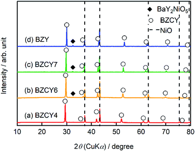 | ||
| Fig. 2 XRD patterns of the thin film fuel cells based on (a) BZCY4, (b) BZCY6 (c) BZCY7, and (d) BZY electrolytes prepared by the SSRS process shown in Fig. 1. For the measurements, the sintered sample is pulverized without screen-printing LSCF. | ||
Fig. 3 shows SEM images of the cross-sections of anode-supported cells after fuel cell tests; all cells comprise three layers: porous LSCF cathodes, dense BaZrxCe0.8−xY0.2O3−δ electrolyte films and porous Ni/BaZrxCe0.8−xY0.2O3−δ cermet anode supports. The recent PCFCs use an electrolyte–electrode composite for the cathode to reduce the cathodic interfacial overpotentials with extended gas–electron–proton triple phase boundaries.15 In this study, however, a single phase LSCF paste is used as a well-defined cathode in all cells because the objective of this study is to clarify optimal Zr contents of BaZrxCe0.8−xY0.2O3−δ electrolytes to obtain satisfactorily high fuel cell efficiency and excellent CO2 tolerance simultaneously.
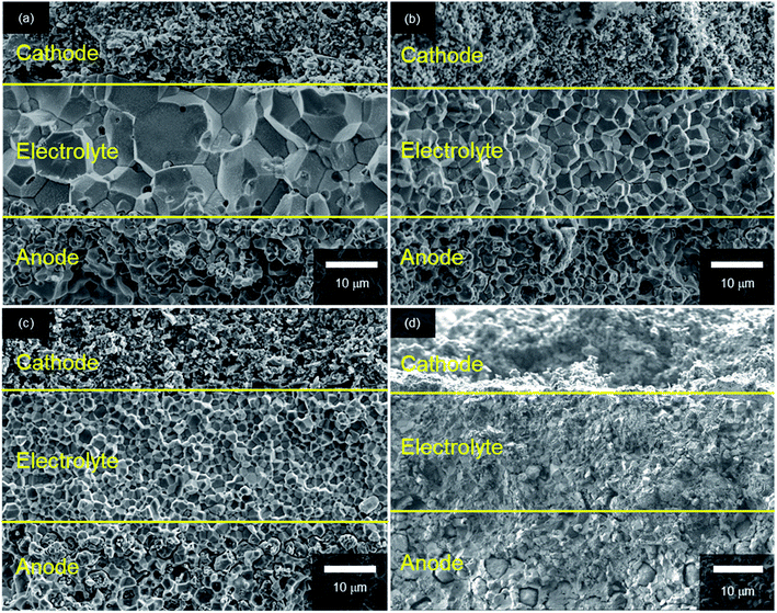 | ||
| Fig. 3 Cross-section SEM micrographs of anode-supported cells with (a) BZCY4, (b) BZCY6, (c) BZCY7 and (d) BZY electrolytes. | ||
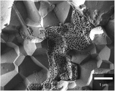
In every case, dense electrolyte films with 30 μm thickness are uniformly formed over a wide area of porous anode supports without apparent cracks or pinholes. The average grain sizes remarkably decrease with the increasing Zr contents. In BZCY4 electrolyte films, the oxide grains exhibit significant growth; their diameter is as large as 5–10 μm (Fig. 3(a)). BZCY6 electrolyte films are also formed by close packing of micrometer grains although the typical grain sizes (4–6 μm) are smaller than those of BZCY4 (Fig. 3(b)). The grain sizes of BZCY7 and BZY are much smaller than those of BZCY6 (Fig. 3(c) and (d)), i.e., they are typically less than 1 μm and thus, their films have a large volume of grain boundaries.10 In addition, porous precipitates are formed at the grain boundaries in the BZY electrolyte film (Fig. 4), which can be identical to Ni particles formed by the reduction of BaY2NiO5 impurity phases under hydrogen atmosphere.19,22 Such metallic Ni segregation is not observed in BZCY6 and BZCY7, indicating that the reaction between BZCY6 or BZCY7 and NiO is much less pronounced than that with BZY.
3.2 Electrochemical performances
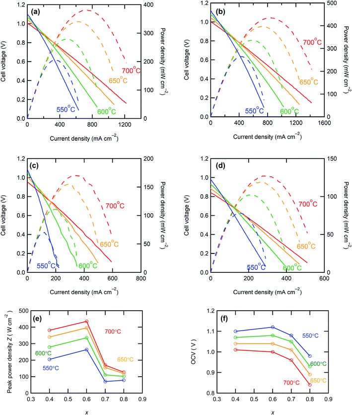
Fig. 5 shows the I–V and I–P curves of all anode-supported cells along with the summary of open circuit voltages (OCVs) and peak power densities (PPDs). The BZCY4- and BZCY6-based cells exhibit sufficiently high open-circuit voltages (OCVs) of more than 1 V in the measured temperature range, which are close to the theoretical values, suggesting that electronic conduction and gas leakage are sufficiently small in BZCY4 and BZCY6 electrolyte thin films. Hence, the BZCY4- and BZCY6-based cells yield significantly high peak power densities (PPDs). The BZCY4-based cell delivers PPD values of 381, 340, 279, and 205 mW cm−2 at 700, 650, 600, and 550 °C, respectively (Fig. 5(f)). Moreover, BZCY6-based cells yield higher PPDs than BZCY4 regardless of the higher Zr contents, and the values reach 435, 396, 336, and 264 mW cm−2 in the same temperature range (Fig. 5(f)). However, the fuel cell performances rapidly deteriorate with further Zr substitution. PPD of the BZCY7-based cell is less than 120 mW cm−2 even at 600 °C although the cell gains OCV of more than 1.0 V at temperatures below 650 °C. PPD of the BZY cell is smaller than that of BZCY7, and OCVs do not reach 1.0 V even at temperatures below 600 °C, which is probably due to electronic leakage mediated via metallic Ni precipitates.To provide further verification for the fuel cell performances, the polarization behavior is studied by electrochemical impedance techniques. Fig. 6 presents the impedance spectra of the fuel cells under OCV conditions. In general, Nyquist plots of the impedance responses of PCFCs provide the x-intercept in a high frequency region, corresponding to electrolyte resistances. After the intercept, they exhibit broad semi-arcs mainly due to interfacial polarization resistances at the cathode side;23 thus, the diameters of the arcs provide polarization resistances. Fig. 7 displays Arrhenius plots of inversed ohmic resistance (Rb) and polarization resistance (Rp) determined from the spectral features of the Nyquist impedance plots. All electrolyte-type cells show Arrhenius-type linear temperature dependence of Rp−1 (Fig. 7(b)), and the related activation energies are similar; the values are 0.94, 0.90, 0.89, and 0.81 eV for BZCY4, BZCY6, BZCY7, and BZY-based cells, respectively, which implies that the cathodic reaction involves the same rate-determining steps. Rp values of BZCY4- and BZCY6-based cells are very close each other at all temperatures, whereas Rp values of BZCY7 and BZY are one order of magnitude larger than the former values, which is probably due to their low proton conductivity,10 as mentioned below.
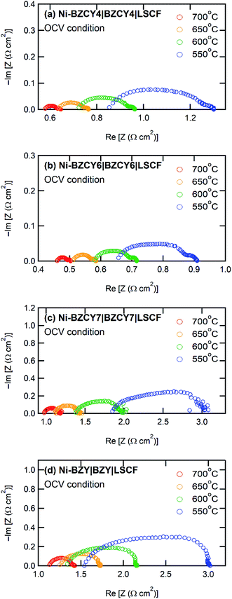 | ||
| Fig. 6 Electrochemical impedance spectra of anode-supported thin film cells with electrolytes of (a) BZCY4, (b) BZCY6, (c) BZCY7, and (d) BZY in fuel cell atmosphere under OCV condition. | ||
 | ||
| Fig. 7 Arrhenius plots of reciprocal of (a) ohmic resistance (Rb) and (b) polarization resistance (Rp) of anode-supported cells. The values of Rb and Rp are determined from the features of impedance Nyquist plots in Fig. 6. (c) Arrhenius plots of proton conductivities of BZCY4, BZCY6, BZCY7, and BZY electrolyte films determined from Rb and film thickness. | ||
Rb−1 obeys linear Arrhenius-type relationship, providing the activation energies of proton conduction of 0.26, 0.33, 0.34, and 0.22 eV for BZCY4, BZCY6, BZCY7, and BZY cells, respectively, and these energies are similar to the corresponding energies reported elsewhere.24–27,31 In all electrolyte cells, the fractions of Rb to total resistances (Rb + Rp) account for 65–80% at 600 °C, indicating that the electrolyte resistances involve the major part of the voltage losses. Rb values of BZCY7 and BZY electrolyte films are one order of magnitude higher than those of BZCY4 and BZCY6, which is due to large grain boundary resistances; the grain boundary volumes of the former are much larger than those of the latter (Fig. 3). The BZCY6-based cell has the lowest ohmic resistance among the four cells (Fig. 6), which is the main reason for obtaining the highest PPD value with the BZCY6-based cell.
The performances of recently reported PCFCs with BZCY4, BZCY6, BZCY7 and BZY electrolyte thin films at 600 °C are summarized in Table 1 for direct comparison; most of these materials were fabricated using chemically synthesized fine powders of BaZrxCe0.8−xY0.2O3 for sintering.5,14,25–36 In recent years, S. Choi et al. reported outstanding performances of BaZr0.4Ce0.4Y0.1Yb0.1O3-δ-based cells with a PrBa0.5Sr0.5Co1.5Fe0.5O5+δ cathodic interlayer, which reached to about 1.1 W cm−2 at 600 °C.37 Although PPD of our BZCY4 cells is lower than this significant result, it is higher than the PPD values reported elsewhere for the anode-supported PCFCs with the same electrolyte5,14,25,26,29 (Table 1). Moreover, the studies on BZCY6 cells are rather rare,30 and PPD of our BZCY6 cells is 3 times higher than that of the analogous cell fabricated with sol–gel-derived fine powders (116 mW cm−2).30 This behavior could be related to the sufficiently low grain boundary resistances of our electrolyte films because the average grain size of our BZCY6 was larger than those of the previously reported cells (ref. 16). Although the BZCY7- and BZY-based cells prepared here possessed low fuel cell performances compared to the other two, their PPDs were higher than those of most of the analogous-electrolyte fuel cells14,27–34 (Table 1). Moreover, PPD of our BZY cell is comparable to that reported for BZY-based thin film fuel cells fabricated by pulsed laser deposition (PLD) at 600 °C (ref. 31) (Table 1). It can be concluded that all electrolyte cells prepared here have equivalent or higher efficiencies than the corresponding high-performance fuel cells reported elsewhere. These features prove that the upper limit of Zr contents in BaZrxCe0.8−xY0.2O3−δ electrolytes is near x = 0.6 to develop a low-resistive, large-grained electrolyte film via a low-temperature reactive sintering process.
| Anode | Electrolyte | Cathode | Rb/Ω cm2 | Thickness/μm | OCV/V | PPD/mW cm−2 | Film conductivity/S cm−1 | Reference |
|---|---|---|---|---|---|---|---|---|
| a La0.6Sr0.4Co0.2Fe0.8O3 (LSCF), Ba0.5Sr0.5Co0.8Fe0.2O3 (BSCF), La0.6Sr0.4CoO3 (LSC), Ba0.5Sr0.5(Co0.8Fe0.2)0.9Ti0.1O3 (BSCFT), NdBa0.5Sr0.5Co1.5Fe0.5O5+δ (NBSCF), BaCo0.4Fe0.4Zr0.1Y0.1O3 (BCFZY), BaZr0.85Y0.15O3 (BZY15), BaCe0.9Yb0.1O3−δ (BCYb), Sm0.5Sr0.5CoO3−δ (SSC), Ce0.8Sm0.2O2−δ (SDC), PrBaCo2O5+δ (PBC), BaZr0.7In0.3O3−δ (ΒΖΙ), BaZr0.1Ce0.7Y0.2O3−δ (BZCY), BaZr0.8Y0.16Zn0.04O3−δ (BZYZn), BaZr0.7Pr0.1Y0.2O3−δ (BZPY), BaZr0.5Pr0.3Y0.2O3−δ (BZPY30), BaZr0.4Ce0.4Y0.1Yb0.1O3 (BZCYYb4411), PrBa0.5Sr0.5Co1.5Fe0.5O5+δ (PBSCF). | ||||||||
| Ni-BZCY4 | BZCY4 | LSCF | 0.71 | 30 | 1.07 | 279 | 4.2 × 10⁻³ | This work |
| Ni-BZCY6 | BZCY6 | LSCF | 0.58 | 30 | 1.08 | 336 | 5.2 × 10⁻³ | This work |
| Ni-BZCY7 | BZCY7 | LSCF | 1.34 | 30 | 1.05 | 111 | 2.7 × 10⁻³ | This work |
| Ni-BZY | BZY | LSCF | 1.32 | 30 | 0.93 | 102 | 2.2 × 10⁻³ | This work |
| Ni-BZCY4 | BZCY4 | BSCF | — | 20 | 1.04 | 230 | — | 5 |
| Ni-BZCY4 | BZCY4 | BSCF | 1.23 | 35 | 1.05 | 159 | 2.8 × 10⁻³ | 14 |
| Ni-BZCY4 | BZCY4 | BSCF | 0.74 | 25 | 1.02 | 276 | 3.4 × 10⁻³ | 25 |
| Ni-BZCY4 | BZCY4 | BSCF | — | 35 | 0.98 | 151 | — | 26 |
| Ni-BZY | BZCY4 | Pr2NiO4 | 0.77 | 5 | 1.03 | 102 | 6.5 × 10⁻⁴ | 28 |
| Ni-BZCY4 | BZCY4 | BZCY4-BSCFT | 0.91 | 20 | 1.03 | 194 | 2.2 × 10⁻³ | 29 |
| Ni-BZCY6 | BZCY6 | BSCF | — | 25 | 1.07 | 116 | — | 30 |
| Ni-BZY | BZY | BSCF | — | 35 | 1 | 22 | — | 14 |
| Ni-BZI | BZI | PBC-BZPY | 2.01 | 15 | 0.946 | 84 | 7.5 × 10⁻⁴ | 27 |
| Ni-BZY | BZY (PLD) | LSCF-BCYb | 1.85 | 4 | 0.99 | 110 | 2.16 × 10⁻⁴ | 31 |
| Ni-BZCY | BZY | SSC-SDC | 3.24 | 25 | 0.97 | 55 | 7.7 × 10⁻⁴ | 32 |
| Ni-BZY | BZYZn | Pt | 1.15 | 20 | 0.94 | 75 | 1.7 × 10⁻³ | 33 |
| Ni-BZY | BZPY | LSCF-BZPY | 1.33 | 20 | 0.93 | 81 | 1.5 × 10⁻³ | 34 |
| Ni-BZY | BZPY | LSCF-BZPY30 | 0.53 | 12 | 0.9 | 163 | 2.26 × 10⁻³ | 35 |
| Ni-BZY | BZY (PLD) | LSC | 0.15 | 2 | 1.0 | 720 | — | 36 |
| Ni-BZCYYb (SSRS) | BZCYYb | BCFZY | 0.29 | 30 | 1.1 | 660 | 1.0 × 10⁻² | 15 |
| Ni-BZCYYb 4411 | BZCYYb 4411 | PBSCF | 0.08 | 15 | 1.03 | 1098 | 1.88 × 10⁻² | 37 |
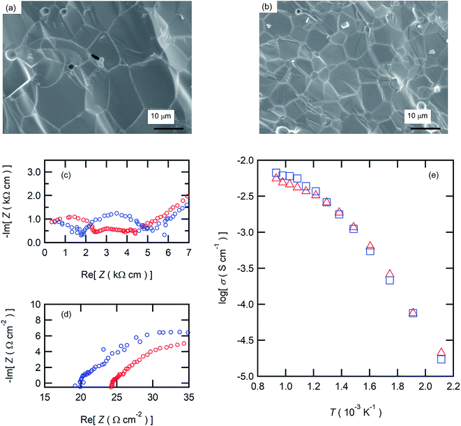
The aforementioned results clearly demonstrate that the BZCY6 cells exhibit superior fuel cell performances compared to BZCY4 cells in spite of the higher Zr contents and smaller grain sizes. Fig. 7(c) displays the proton conductivity (σ) of the electrolyte films determined from Rb and film thickness; BZCY6 has higher conductivity than BZCY4 even though the grain boundary volumes of the former are apparently larger than those of the later. To verify this point, we examine the proton conductivities of BZCY4 and BZCY6 bulk ceramics prepared by an SSRS process that is similar to the one used for the fabrication of anode-supported cells. The BZCY4 and BZCY6 ceramics thus prepared have highly dense matrices (relative density of >97%), with grain sizes equal to 10 and 5 μm diameter, respectively (Fig. 8(a) and (b)); these results are in agreement with the grain sizes observed for the thin film fuel cell (Fig. 3). The impedance spectra of both ceramics show apparent bulk and interfacial contributions in high (106–105 Hz) and middle (105–102 Hz) frequency ranges, respectively, at relatively low temperatures together with electrode contribution in low frequency region (<102 Hz), as shown in Fig. 8(c). The bulk resistance of BZCY6 is lower than that of BZCY4, whereas the interfacial resistance of BZCY6 is higher than that of BZCY4 and thus, the total resistance of BZCY6 is 20% larger than that of BZCY4 at 200 °C; after increasing the temperature to 550 °C, both show only an x-intercept in the frequency range of 106–104 Hz due to sufficiently reduced resistances.9 The x-intercept of BZCY6 is clearly smaller than that of BZCY4 at 550 °C.
Fig. 8(e) displays the Arrhenius plots of the total conductivity of the BZCY4 and BZCY6 bulk ceramics determined by the sum of the bulk resistances and grain-boundary resistances. In both, the slopes of the plots change at around 400 °C, indicating that dominant conduction mechanism has changed at this temperature. For many BaZrxCe0.8−xY0.2O3−δ systems, it has been reported that the grain boundary resistances are dominant in the low-temperature region, whereas these are smaller than the bulk resistances in the high-temperature region, because the activation energies of grain boundary conduction are larger than those of the bulk.38 Accordingly, the relatively high total conductivity of BZCY6 can be due to the bulk conductivity being higher than that of BZCY4 (Fig. 8(e)). In fact, this feature is in agreement with the previously reported result.9 These results prove that the superior fuel cell performances of BZCY6 can be due to relatively high proton conductivities in the IT ranges.
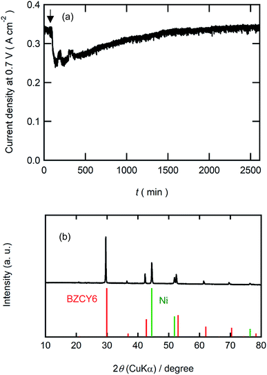
Finally, we examined the durability of BZCY6 under CO2-containing fuel conditions. Fig. 9(a) shows current decays of BZCY6 cells in potentiostatic operation at 0.7 V with 1% CO2-containing hydrogen fuels. The cell keeps outputting a constant current of about 330 mA cm−2 for 2 days with CO2-containing fuels although the current slightly decreases just after the introduction of CO2. XRD measurements of the BZCY6 cell after durability tests confirm that decomposition products such as BaCO3, ZrO2 and CeO2 are not formed even after fuel cell operations for several hours under a CO2 atmosphere (Fig. 9(b)), which reveals that BZCY6 is thermodynamically stable under CO2-containing fuel conditions. The current results unambiguously demonstrate that BZCY6 is a promising electrolyte for intermediate temperature PCFC with excellent low-temperature sinterability and CO2 tolerance.
4. Conclusion
Herein, high performance anode-supported cells with Zr-rich BaZrxCe0.8−xY0.2O3 (x = 0.4, 0.6, 0.7, and 0.8) were successfully fabricated by solid-state reactive sintering (SSRS) with Zn(NO3)2 additives by a single sintering step at 1400 °C. For x = 0.4 and 0.6, BaZrxCe0.8−xY0.2O3 ceramics exhibited excellent sinterability and thus, densely packed films comprising μm-sized grains were obtained by sintering at a relatively low temperature with the aid of Zn additives. According to the large-grained microstructures, the ohmic resistances of these electrolyte films were smaller than those reported for the analogous thin film and thus, the cells with x = 0.4 and 0.6 exhibited highly efficient power generation, yielding peak power densities of 279 and 336 mW cm−2 at 600 °C, respectively, which were comparable to or several times higher than those of the analogous thin film fuel cells prepared from sol–gel-derived BaZrxCe0.8−xY0.2O3 powders. BaZr0.6Ce0.2Y0.2O3 was found to have higher proton conductivity than BaZr0.4Ce0.4Y0.2O3 at temperatures above 500 °C despite the relatively high Zr contents and thus, it showed excellent durability under CO2-containing atmosphere. The preceding results encourage the development of high-performance PCFCs with thermally stable, Zr-enriched BaZr0.6Ce0.2Y0.2O3 electrolytes.Conflicts of interest
There are no conflicts to declare.Acknowledgements
This work was granted by MIRAI project (JPMJMI17E8) of Japanese Agency of Science and Technology (JST). A part of this work was conducted at Laboratory of XPS analysis, Joint-use facilities, Hokkaido University, supported by “Material Analysis and Structure Analysis Open Unit (MASAOU)”.References
- E. P. Murray, T. Tsai and S. A. Barnett, Nature, 1999, 400, 649 CrossRef.
- E. Ivers-Tiffée, et al., J. Eur. Ceram. Soc., 2001, 21, 1805 CrossRef.
- A. Boudghene Stambouli and E. Traversa, Renewable Sustainable Energy Rev., 2002, 6, 433 CrossRef.
- A. Esquirol, N. P. Brandon, J. A. Kilner and M. Mogensen, J. Electrochem. Soc., 2004, 151, A1847 CrossRef.
- Y. Guo, R. Ran and Z. Shao, Int. J. Hydrogen Energy, 2010, 35, 5611 CrossRef.
- K. D. Kreuer, Annu. Rev. Mater. Res., 2003, 33, 333 CrossRef.
- W. Zajac, D. Rusinek, K. Zheng and J. Molenda, Cent. Eur. J. Chem., 2013, 11, 471 Search PubMed.
- K. Katahira, Y. Kohchi, T. Shimura and H. Iwahara, Solid State Ionics, 2000, 138, 91 CrossRef.
- P. Sawant, S. Varma, B. N. Wani and S. R. Bharadwaj, Int. J. Hydrogen Energy, 2012, 37, 3848 CrossRef.
- E. Fabbri, A. D'Epifanio, E. D. Bartolomeo, S. Licoccia and E. Traversa, Solid State Ionics, 2008, 179, 558 CrossRef.
- S. B. C. Duval, P. Holtappels, U. F. Vogt, U. Stimming and T. Graule, Fuel Cells, 2009, 9, 613 CrossRef.
- S. M. Haile, G. Staneff and K. H. Ryu, J. Mater. Sci., 2001, 36, 1149 CrossRef.
- E. Fabbri, D. Pergolesi and E. Traversa, Chem. Soc. Rev., 2010, 39, 4355 RSC.
- Y. Guo, Y. Liu, R. Ran and Z. Shao, J. Power Sources, 2009, 193, 400 CrossRef.
- C. Duan, J. Tong, M. Shang, S. Nikodemski, M. Sanders, S. Ricote, A. Almansoori and R. O'Hayre, Science, 2015, 349, 1321 CrossRef PubMed.
- S. Nikodemski, J. Tong and R. O'Hayre, Solid State Ionics, 2013, 253, 201 CrossRef.
- R. D. Shannon, Acta Crystallogr., Sect. A: Cryst. Phys., Diffr., Theor. Gen. Crystallogr., 1976, 32, 751 CrossRef.
- J. Tong, D. Clark, M. Hoban and R. O'Hayre, Solid State Ionics, 2010, 181, 496 CrossRef.
- J. Tong, D. Clark, L. Bernau, A. Subramaniyan and R. O'Hayre, Solid State Ionics, 2010, 181, 1486 CrossRef.
- L. Bi, E. Fabbri, Z. Sun and E. Traversa, Energy Environ. Sci., 2011, 4, 1352 RSC.
- J. Tong, D. Clark, L. Bernau, M. Sanders and R. O'Hayre, J. Mater. Chem., 2010, 20, 6333 RSC.
- W. G. Coors, “Protonic ceramics of the solid solution BaCexZr0.8−xY0.2O3−δ prepared by NiO-reactive sintering. Part I: fabrication and microstructure’’, CoorsTek report (available from the author), March 18th, 2010 Search PubMed.
- A. Jun, J. Kim, J. Shin and G. Kim, ChemElectroChem, 2016, 3, 511 CrossRef.
- S. H. Nien, C. S. Hsu, C. L. Chang and B. H. Hwang, Fuel Cells, 2011, 11, 178 CrossRef.
- Y. Liu, Y. Guo, R. Ran and Z. Shao, J. Membr. Sci., 2013, 437, 189 CrossRef.
- Y. Guo, R. Ran and Z. Shao, Int. J. Hydrogen Energy, 2011, 36, 1683 CrossRef.
- L. Bi, E. Fabbri, Z. Sun and E. Traversa, Solid State Ionics, 2011, 196, 59 CrossRef.
- N. Nasani, D. Ramasamy, S. Mikhalev, A. V. Kovalevsky and D. P. Fagg, J. Power Sources, 2015, 278, 582 CrossRef.
- L. Bi, E. Fabbri and E. Traversa, Electrochem. Commun., 2012, 16, 37 CrossRef.
- Y. Liu, R. Ran, M. O. Tade and Z. Shao, J. Membr. Sci., 2014, 467, 100 CrossRef.
- D. Pergolesi, E. Fabbri and E. Traversa, Electrochem. Commun., 2010, 12, 977 CrossRef.
- J. Xiao, W. P. Sun, Z. W. Zhu, Z. T. Tao and W. Liu, Mater. Lett., 2012, 73, 198 CrossRef.
- I. Liusetto, S. Licoccia, A. D'Epifanio, A. Sanson, E. Mercadelli and E. Di Bartolomeo, J. Power Sources, 2012, 220, 280 CrossRef.
- E. Fabbri, L. Bi, H. Tanaka, D. Pergolesi and E. Traversa, Adv. Funct. Mater., 2011, 21, 158 CrossRef.
- E. Fabbri, L. Bi, J. L. M. Rupp, D. Pergolesi and E. Traversa, RSC Adv., 2011, 1, 1183 RSC.
- K. Bae, D. Y. Jang, H. J. Choi, D. Kim, J. Hong, B. K. Kim, J. H. Lee, J. W. Son and J. H. Shim, Nat. Commun., 2017, 8, 14553 CrossRef PubMed.
- S. Choi, C. J. Kucharczyk, Y. Liang, X. Zhang, I. Takeuchi, H. Ji and S. M. Haile, Nat. Energy, 2018, 3, 202 CrossRef.
- S. Ricote, N. Bonanos, A. Manerbino and W. G. Coors, Int. J. Hydrogen Energy, 2012, 37, 7954 CrossRef.
| This journal is © The Royal Society of Chemistry 2018 |


