 Open Access Article
Formation of Mn–Cr mixed oxide nanosheets with enhanced lithium storage properties†
Liewu Li a,
Liping Wangab,
Mingyu Zhang*a and
Qizhong Huanga
aState Key Laboratory of Powder Metallurgy, Central South University, Changsha, 410083, China. E-mail: zhangmingyu@csu.edu.cn
bDepartment of Biological and Environmental Engineering, Changsha University, Changsha, 410022, China
First published on 21st August 2018
Abstract
Novel carbon-free Mn2O3/MnCr2O4 hybrid nanosheets are synthesized through thermal decomposition of the facilely co-precipitated Mn–Cr binary hydroxide and a carbonate hybrid precursor. As an anode for lithium-ion batteries, the Mn2O3/MnCr2O4 electrode delivers a wonderful electrochemical performance, i.e., an enhanced stability of 913 mA h g−1 at a current density of 1 A g−1 after 300 cycles, and an excellent rate performance. The excellent electrochemical performance of the Mn2O3/MnCr2O4 electrode can be ascribed to the interconnected nanosheets and porous structure, as well as the possible synergistic effects between Mn and Cr mixed oxides.
1. Introduction
With the economic growth and the demands of climate protection, rechargeable lithium-ion batteries (LIBs) have established themselves in dominant roles for portable electronic devices and electric vehicles.1–4 However, conventional anode materials of graphite cannot meet the urgent demands for heavy-duty applications due to the low theoretical capacity, poor rate performance and serious safety issues owing to the formation of lithium dendrites on its surface even at a charging current density of 4 mA cm−2.5,6 In order to meet the requirements for large-scale energy storage, transition metal oxides (TMOs, M = Mn, Fe, Co, Ni, Cu, Cr, etc.), especially those of mixed valence oxides involving different metal elements, have been extensively exploited as very promising alternatives to graphite as anode materials (TMOs have about twice the capacity of carbon per unit mass, and three times its density, therefore, TMOs have about 6 times the capacity of carbon per unit volume).7–10 Although TMO anode materials exhibit high theoretical capacity for LIBs, they are seriously hampered by the gigantic volume changes and dramatic mechanical stress upon lithiation and delithiation, resulting in cracking and pulverization and loss of electrical contact between particles and the current collector, thereby leading to rapid capacity fading.11,12 In order to solve these issues, introducing a second phase element or multiphase materials has proved to be an effective way for the transition metal to increase the electronic conductivity, improve Li+ diffusivity, separate the multiphase phases from each other, buffer volume change, as well as accommodate structural stress generated during cycling.13–28So far many relevant studies have been reported about multiphase TMOs nanocomposite anodes with excellent electrochemical performance.29–33 Liu et al. showed that by substituting a small amount of Cu into a Co3O4 lattice uniformly, the resulting composite electrode material (Cu3/7Co18/7O4) can endure large volume change caused by lithiation/delithiation cycles, thereby maintaining high capacity and cycling stability.34 Lin et al. found that Cr2O3@Ag2O composite showed much higher specific capacity and better cycling stability than those of bare Cr2O3 as anode material for LIBs.35 Zhou et al. fabricated CoMn2O4@TiO2 submicrospheres for advanced LIBs, after 500 cycles at a current density of 1 A g−1, the CoMn2O4@TiO2 spheres possessed a high reversible capacity of 940 mA h g−1.36 Despite these achievements in research of multiphase TMOs nanocomposite anodes, the preparation methods are laborious and the cost is not suitable for mass production. Thus, excellent rate capability, outstanding stability and affordable TMOs ande materials produced by scalable synthesis approach should be developed urgently.4
Among the TMOs, manganese oxides (MnOx) have proved to be attractive choices because of their high theoretical capacity, low potential, high abundance and environmental benignity.12,37–43 Cr2O3 also has been considered as a promising anode material for its high theoretical capacity of 1058 mA h g−1 and relatively low lithium insertion potential among metal oxides and low-cost.11,44–47 MnCr2O4 is an important member of the spinel family and has the normal spinel structure (space group Fd![[3 with combining macron]](https://www.rsc.org/images/entities/char_0033_0304.gif) m).48,49 The MnCr2O4 spinel has been widely investigated due to its excellent magnetic and electric properties.50 However, to the best of our knowledge, MnCr2O4 has not been reported as the anode material for LIBs. Thus, the development of a facile method to synthesize nanostructure MnCr2O4 and its composites and elucidation of their electrochemical reaction mechanism for LIBs is of great importance and necessity.
m).48,49 The MnCr2O4 spinel has been widely investigated due to its excellent magnetic and electric properties.50 However, to the best of our knowledge, MnCr2O4 has not been reported as the anode material for LIBs. Thus, the development of a facile method to synthesize nanostructure MnCr2O4 and its composites and elucidation of their electrochemical reaction mechanism for LIBs is of great importance and necessity.
Herein, we report as first time a co-precipitation method for large-scalable fabrication of the Mn2O3/MnCr2O4 hybrid nanosheets based on the recent investigations. The facile synthesis approach has the features of scalable capability, environmentally friendly and low cost. As an anode for LIBs, the Mn2O3/MnCr2O4 electrode delivers an excellent rate performance and an enhanced reversible capacity of 913 mA h g−1 at a current density of 1 A g−1 after 300 cycles. Those outstanding electrochemical performances can be ascribed to the unique boundaries between MnCr2O4 and Mn2O3, which can promote Li+ diffusion through the electrode. Furthermore, the structure of interconnected nanosheets and pores can improve electron conductivity in the continuous paths and ensure the electrode full contact with the electrolyte to possess abundant mass-transportation channels, moreover, accommodate a large volume change during charge and discharge processes. Improved rate capacity and cycling stability open the door to design of high-performance LIBs anodes.
2. Experimental section
Preparation of the Mn2O3/MnCr2O4 hybrid nanosheets
First, MnCl2·4H2O (40 mmol) and CrCl3·6H2O (20 mmol) were dissolved in 100 mL of deionized water (solution 1), NaOH (140 mmol) and Na2CO3 (56 mmol) were also dissolved in 100 mL of deionized water (solution 2). Then solution 2 was dropwise added into solution 1, stirring at the same time. The obtained suspension was maintained at 80 °C for 48 h in an oven with sufficient ageing. Next, the precipitate was washed by centrifugal washing and dried at 80 °C for 12 h. Finally, the as-dried precursor was heated in air at 5 °C min−1 up to 800 °C, kept at this temperature for 2 h, and cooled naturally to room temperature. Grounded by agate mortar to obtain very fine composite powder (≈100 mesh), the Mn2O3/MnCr2O4 hybrid nanosheets was synthesized. The same procedures were applied to synthesize the Mn2O3 and Cr2O3 nanomaterials.Materials characterization
The morphology and crystal structure of the samples were characterized by scanning electron microscopy (SEM, FEI Nova Nano SEM230), energy dispersive X-ray spectroscopy (EDX, FEI Nova Nano SEM230), transmission electron microscopy (TEM, JEOL JEM-2010), and X-ray diffraction (XRD, Rigaku Dmax/2550 VB + 18 kW). The surface chemical composition of the samples was identified by X-ray photoelectron spectroscopy (XPS) using a multifunctional imaging electron spectrometer (Thermo ESCALAB 250XI) with monochromatic Al Kα radiation. The specific surface areas and pore size distribution of the samples were evaluated from nitrogen adsorption–desorption isotherms using a Quadrasorb SI surface characterization analyzer.Electrochemical testing
The electrodes were prepared by mixing 70 wt% active material, 20 wt% acetylene carbon black and 10 wt% polyvinylidene fluoride. Then dissolved the mixture in N-methyl-2-pyrrolidinone to form slurry. The obtained slurry was coated on copper foil, then dried at 80 °C for 12 h under vacuum. Coin cells (CR2032) were fabricated using lithium metal as the counter electrode, Celgard 2400 as the separator, and LiPF6 (1 M) in ethylene carbonate (EC) and dimethyl carbonate (DMC) with a 1![[thin space (1/6-em)]](https://www.rsc.org/images/entities/char_2009.gif) :
:![[thin space (1/6-em)]](https://www.rsc.org/images/entities/char_2009.gif) 1 volume ratio as the electrolyte. The assembly of the cell was conducted in an Ar-filled glove box with oxygen and moisture contents less than 1 ppm. All measurements were carried out at 25 °C. CV measurements were conducted at 0.1 mV s−1 within the range of 0.01–3.0 V (vs. Li/Li+) on a CHI660E electrochemical workstation. Cycle life and rate capability of the cells were tested within a voltage window of 0.01–3.0 V (vs. Li/Li+) by using a battery testing system (LAND CT2001A, China) at current densities ranging from 0.1 to 3 A g−1. EIS experiments were carried out using a CHI660E electrochemical workstation in the frequency range of 100 kHz to 0.01 Hz.
1 volume ratio as the electrolyte. The assembly of the cell was conducted in an Ar-filled glove box with oxygen and moisture contents less than 1 ppm. All measurements were carried out at 25 °C. CV measurements were conducted at 0.1 mV s−1 within the range of 0.01–3.0 V (vs. Li/Li+) on a CHI660E electrochemical workstation. Cycle life and rate capability of the cells were tested within a voltage window of 0.01–3.0 V (vs. Li/Li+) by using a battery testing system (LAND CT2001A, China) at current densities ranging from 0.1 to 3 A g−1. EIS experiments were carried out using a CHI660E electrochemical workstation in the frequency range of 100 kHz to 0.01 Hz.
3. Results and discussion
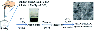
The Mn2O3/MnCr2O4 hybrid nanosheets was prepared by a facile three-step process involving coprecipitation, lavation and calcination (Fig. 1). First, MnCl2 and CrCl3 were dissolved in deionized water to form a transparent solution containing Mn2+ and Cr3+. Similarly, NaOH and Na2CO3 were dissolved in deionized water to form a mixing transparent solution containing OH− and CO32−. Then, the latter solution was dropwise added into the former solution, stirring at the same time to form a uniform suspension contained Mn(OH)2, Cr(OH)3, MnCO3 and Cr2(CO3)3. Through post-thermal calcination, the Mn2O3/MnCr2O4 hybrid nanosheets was obtained. It worth noting that Mn–Cr binary hydroxides and carbonates hybrid precursor can be uniformly formed efficiently by the facile co-precipitated method. Furthermore, the porous structures were well formed due to the release of CO2 gas during thermal decomposition of the Mn–Cr binary carbonates.42 The details of material synthesis and characterization methods are presented in the experimental section.From the scanning electron microscopy (SEM) images of the Mn2O3/MnCr2O4 hybrid nanosheets observed in Fig. 2a and b, there are many nanosheets structures and it interconnected with each other. The interconnected nanosheets structures can not only supply enough space to buffer volume change and accommodate structural stress generated during cycling, but also shorten electronic and ionic transport length.10,39 The energy dispersive X-ray spectroscopy (EDX) in Fig. 2c–f reveals the existence of Mn, Cr and O verifying the ingredients of the Mn2O3/MnCr2O4 hybrid nanosheets, and it can be seen that Mn, Cr and O are homogeneously distributed in the entire nanosheets. SEM images of the Mn2O3 and Cr2O3 nanomaterials are shown in Fig. S1 and S2 (ESI).† The atomic contents of Mn and Cr elements in the Mn2O3/MnCr2O4 hybrid nanosheets composite were about 43.26% and 20.17%, respectively, which are determined by the EDX (ESI, Fig. S3†). The results are in good agreement with the initial ratio of manganese chloride and chromic chloride. Therefore, the ratio of Mn2O3 and MnCr2O4 in the hybrid nanosheets composite is ∼3![[thin space (1/6-em)]](https://www.rsc.org/images/entities/char_2009.gif) :
:![[thin space (1/6-em)]](https://www.rsc.org/images/entities/char_2009.gif) 2.
2.
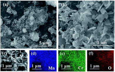 | ||
| Fig. 2 (a) SEM image of the Mn2O3/MnCr2O4 hybrid nanosheets; (b) high magnification image of (a); (c)–(f) SEM image and Mn, Cr and O elemental mapping of the Mn2O3/MnCr2O4 hybrid nanosheets. | ||
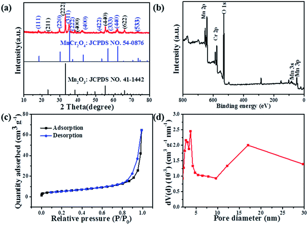
The typical XRD pattern of the as-prepared Mn2O3/MnCr2O4 hybrid nanosheets is present in Fig. 3a. Three sharp and intense peaks at around 33.0°, 38.2° and 55.2° are well indexed to the (222), (400) and (440) planes of the cubic Mn2O3 phase (JCPDS card no. 41-1442), respectively. Another three sharp and intense peaks at around 30.0°, 35.3° and 61.2° are well indexed to the (220), (311) and (440) planes of the cubic MnCr2O4 phase (JCPDS card no. 54-0876). The XRD patterns of the Mn2O3 and Cr2O3 nanomaterials show in Fig. S4 (ESI).† X-ray photoelectron spectroscopy (XPS) was implemented to investigate the elemental composition, chemical states. Feature peaks in the survey spectra corresponding to Mn 2p, Cr 2p and O 1s (Fig. 3b). Corresponding to previous literature, the peaks at 653.2 eV and 641.5 eV in Fig. S5a (ESI)† are ascribed to Mn 2p1/2 and Mn 2p3/2, and the bonding energies at the Mn 2p1/2 and Mn 2p3/2 peaks agree well with that of reported for Mn2O3.43 The Mn 2p XPS spectrum exhibited three characteristic peaks at 640.4 eV, 641.8 eV and 643.9 eV, corresponding to spin–orbit peaks of manganese with mixed valence states of +2, +4 and +3, respectively.51 Similarly, in the Cr 2p XPS spectra, the high-resolution spectra of Cr 2p in Fig. S5b (ESI)† shows two distinct peaks at 586.1 eV and 576.7 eV, which are respectively ascribed to Cr 2p1/2 and Cr 2p3/2 levels, respectively.52 The peak fitted at 575.7 eV, 576.8 eV and 578.6 eV mainly belong to Cr2+ 2p3/2, Cr4+ 2p3/2 and Cr3+ 2p3/2 respectively. Consequently, both mixed valence states of +2, +4 and +3 coexisted for manganese and chromium in the as-prepared composites. Brunauer–Emmett–Teller (BET) measurement was carried out to evaluate the specific surface area and pore size distribution of the Mn2O3/MnCr2O4 hybrid nanosheets (Fig. 3c). A typical IV isotherm with a distinct hysteresis loop in the range of 0.8–1.0 P/Po can be clearly seen, indicating its mesoporous structures.53 The BET-specific surface area of the Mn2O3/MnCr2O4 hybrid nanosheets is estimated to be 19.8 m2 g−1. The pore size distribution calculated from the Barrett–Joyner–Halenda (BJH) method, mesopores distribute from 2.68 to 17.01 nm in the Mn2O3/MnCr2O4 hybrid nanosheets, and the total pore volume of the nanostructures is calculated to be 0.1 cm3 g−1 (Fig. 3d). High surface area of the Mn2O3/MnCr2O4 hybrid nanosheets is beneficial to the electrode contact with the electrolyte, moreover, suitable pore size and sufficient pore volume are more favorable for the Li+ diffusion and alleviating the volumetric expansion during the lithiation and delithiation processes, leading to enhanced cycle performance.54
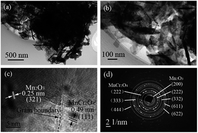
For more accurate information about the morphology and crystal structure, transmission electron microscopy (TEM) was utilized to characterize the interior structure of the Mn2O3/MnCr2O4 hybrid nanosheets. Fig. 4a clearly illustrates the nanosheets structure, which is in good agreement with the SEM image in Fig. 2b. The nanosheets structure is supposed to accommodate the volume expansion of the Mn2O3/MnCr2O4 during the lithiation process. It also can be clearly observed from the high-resolution TEM image in Fig. 4b that each nanosheet of the Mn2O3/MnCr2O4 criss-cross. Fig. 4c reveals the crystalline nature of Mn2O3 and MnCr2O4, the observed d-spacing of 0.49 nm corresponds to the (111) plane of cubic MnCr2O4,48 and the observed d-spacing of 0.25 nm corresponds to the (321) plane of cubic Mn2O3. An obvious grain boundary can be observed between the Mn2O3 (321) lattice plane and the MnCr2O4 (111) lattice plane, indicating that Mn2O3 and MnCr2O4 strongly bonded with each other, and it is good for preventing the Mn or Cr from aggregation during the lithiation/delithiation processes. Further more, grain boundaries can introduce fast paths for Li+ diffusion.55 Additional crystal structure of the Mn2O3/MnCr2O4 hybrid nanosheets was analyzed by the selected area electron diffraction (SAED) patterns (Fig. 4d). The SAED patterns confirm that the nanosheets are Mn2O3 and MnCr2O4 hybrid phase, which are in good agreement with the XRD results.
The electrochemical performance of the Mn2O3/MnCr2O4 hybrid nanosheets and other comparison anode materials have been investigated using lithium ion half cells. All of the electrochemical measurements were tested between 0.01 and 3.0 V (vs. Li/Li+) at 25 °C.
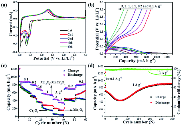
Fig. 5a displays the typical cyclic voltammetry (CV) curves of the Mn2O3/MnCr2O4 electrode for the initial five cycles at a scan rate of 0.1 mV s−1. In the initial cathodic process, the small peak at about 0.81 V is resulted from the formation of a solid–electrolyte interface (SEI) film.12 Further more, two main lithiation peaks centered at 0.30 and 0.11 V can be assigned to the conversion reaction of the Mn2O3 and MnCr2O4 with lithium.11,12 For the second and following cycles, the peaks located at 0.81 V and 0.11 V disappeared, and the reduction peak shifted to higher potential of 0.44 V due to the improved reaction kinetics after the first lithiation.37 During the anodic process, the oxidation peak located at 1.3 V in the reverse sweep is ascribed to the re-oxidation of metallic Mn/MnO, Cr/Cr2O3 and the decomposition of Li2O.11,12 The charge–discharge profiles at the current densities of 0.1, 0.2, 0.5, 1, 2 and 3 A g−1 for the 1st, 11th, 16th, 21st, 31st and 36th cycles are displayed in Fig. 5b. The potential of the Mn2O3/MnCr2O4 electrode increases/decreases monotonically with obvious potential plateau when charge/discharge at various current density, which is a typical behavior of ion conversion dominated energy storage mechanism.9 The distinct plateaus at around 0.5 V and 1.3 V in the discharge and charge profiles are in accordance with the CV curves, matching well with the reduction and oxidation of Mn3+ and Mn, respectively. The distinct plateaus at around 0.2 V and 0.15 V in the discharge profile can be related to the reduction of Mn2+ to the Li2O/Mn and Cr3+ to the Li2O/Cr.56,57 The first discharge and charge capacities are 1207 mA h g−1 and 880 mA h g−1, respectively. The ∼27% irreversible capacity loss for the first cycle can be ascribed to the formation of the SEI layer and the decomposition of the electrolyte.37 The electrochemical reactions during cycling can be concluded as follows:
| Mn2O3 + 6Li+ + 6e− → 2Mn + 3Li2O | (1) |
| MnCr2O4 + 8Li+ + 8e− → Mn + 2Cr + 4Li2O | (2) |
| 2Cr + 3Li2O ↔ Cr2O3 + 6Li+ + 6e− | (3) |
| Mn + Li2O ↔ MnO + 2Li+ + 2e− | (4) |
It is worth pointing out that the reversed conversion (oxidation) potential of metal Mn to MnO (1.3 V) during Li+ extraction process is higher than the conversion oxidation potential of metal Cr to Cr2O3 (1.27 V).56,58 In other words, the formed well-dispersed Mn nanoparticles in Cr/Li2O matrices after full lithiation of the Mn2O3/MnCr2O4 can work as anchors to effectively prohibit the diffusion and coarsening of Cr nanocrystals during the reversed conversion reactions of Cr, giving rise to the obviously enhanced cycling efficiency and stability.
The upgrade of electrochemical properties is also reflected in rate performances, and the comparison between the Mn2O3, Mn2O3/MnCr2O4 and Cr2O3 electrodes were evaluated in the range from 0.1 to 3 A g−1 (Fig. 5c). For the Mn2O3/MnCr2O4 electrode, the average reversible discharge capacities of ∼861, 734, 712, 577, 451 and 366 mA h g−1 are obtained at 0.1, 0.2, 0.5, 1, 2 and 3 A g−1, respectively. Obviously, the capacity gradually falls off as the current density increases but still remains relatively high. When the current density is reduced back to 0.2 A g−1, the charge capacity also recovers to 693 mA h g−1, indicating the high stability as well as excellent reversibility of the electrode. The rate performance of the Mn2O3/MnCr2O4 electrode is obviously much better than those of Mn2O3 and Cr2O3 electrodes. The excellent rate capability may be benefited from the presence of the interconnected nanosheets and porous structure, as well as the grain boundaries for elevating the transportation of both Li+ and electrons.10
To understand the capacity and stability of the Mn2O3, Mn2O3/MnCr2O4 and Cr2O3 electrodes, the cycling stability test was carried out at a current density of 1 A g−1 for 200 cycles (ESI, Fig. S6†). The initial Coulombic efficiency of the Mn2O3, Mn2O3/MnCr2O4 and Cr2O3 electrodes are 55.4%, 72.9% and 79.2%, respectively. In the first cycle, a large irreversible capacity can be observed because of the formation of the SEI composite.37 The discharge capacities of the Mn2O3, Mn2O3/MnCr2O4 and Cr2O3 electrodes are 400, 854 and 113 mA h g−1 in the 200th cycle, respectively. The discharge capacity retention rate of the Mn2O3, Mn2O3/MnCr2O4 and Cr2O3 electrodes are 74.5%, 104.8% and 38.3% compared with the 2nd cycle, respectively. The discharge capacity of the Mn2O3 decreases to 242 mA h g−1 in the 66th cycle, then increases to 429 mA h g−1 in the 157th cycle, after that, the capacity decreases slowly. The discharge capacity of the Mn2O3/MnCr2O4 electrode shows an obvious capacity fading to 442 mA h g−1 in the 64th cycle, then increases continuously to 854 mA h g−1 in the 200th cycle. The discharge capacity of the Cr2O3 electrode falls down rapidly to 164 mA h g−1 in the 10th cycle, then decreases slowly. The phenomenon may be ascribed to the comprehensive effects of the continuous formation of the SEI film on the new active surfaces caused by the repetitive volume change during the discharge/charge cycles.59 The lithiation induced reactivation of the Mn2O3 and Mn2O3/MnCr2O4 electrodes is a similar phenomenon observed in transition metal oxide electrodes.7,8 The excellent stability of the Mn2O3/MnCr2O4 electrode also can be ascribed to the special structure of the nanosheets and porous structure, which can effectively buffer volume expansion and prevent the aggregation during the conversion processes of the formation and decomposition of Li2O, accompanying the reduction and oxidation of metal nanoparticles.10,11,44
The cycling performances of the Mn2O3/MnCr2O4 electrode at the current densities of 0.1, 0.5 and 1 A g−1 show in Fig. 5d and Fig. S7 (ESI).† Under different current densities, the discharge capacities show the same tendency, gradually decreases first, then increases, it obtains 913 mA h g−1 at 1 A g−1 in the 300th cycle, more than 200% capacity recovery from the lowest value at the same rate. The drastic capacity fading is caused by the lithiation-induced mechanical degradation and the formation of unstable SEI.60 The gradually increasing capacity can be reasonably explained by the electrochemical activation of active materials and electrochemical catalysis of Li2O and metal grains, which is a common phenomenon observed in other TMOs.61 The coulombic efficiency increases to 98% after three initial cycles, and then remains over this level until 400 cycles are completed. High coulombic efficiency indicates that a stable SEI layer formed during the initial cycles. With the formation of a stable SEI layer, the structure-refined electrode exhibits a higher reversible specific capacity. The Mn2O3/MnCr2O4 electrode also exhibits a long cycling performance at a high current density of 3 A g−1 for 1000 cycles (ESI, Fig. S8†). The discharge capacity gradually decreases to 208 mA h g−1 in the 159th cycle, then increases to 380 mA h g−1 in the 322th cycle, and it still obtains 320 mA h g−1 in the 1000th cycle.
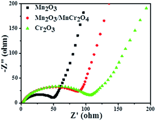
To further reveal the differences of transport kinetics, the electrochemical impedance spectra (EIS) of all materials were analyzed. Fig. 6 displays the Nyquist plots of the Mn2O3, Mn2O3/MnCr2O4 and Cr2O3 electrodes. As observed in the Nyquist plots, all the three samples show a compressed semicircle in the high frequency region and an inclined line in the low-frequency region, which can be assigned to the charge-transfer resistance and semidiffusion of Li+ respectively.18 It can be clearly observed that the Mn2O3 nanocomposite electrode shows the lowest charge transfer resistance, and Mn2O3/MnCr2O4 electrode has a significantly lower charge transfer resistance than the Cr2O3 electrode, suggesting that increase the content of Mn2O3 can improve the electrical conductivity of Mn2O3/MnCr2O4 electrode. So the Mn2O3/MnCr2O4 electrode obtained more transport channels for electrons and Li+. Herein, not only can be the particular structure of the Mn2O3/MnCr2O4 nanosheets mitigates the aggregation and contact resistance, but it also can provide a short way for electrons and ions to transfer, which is in favor of its outstanding electrochemical performance.
Surface SEM images of the Mn2O3/MnCr2O4 electrode at 0th and 1000th cycles were measured to confirm the influence of nanosheets structure on the integrity of electrodes after cycling (Fig. 7). Surface of the Mn2O3/MnCr2O4 electrode before cycling has uniform mixed active materials and conductive agents with integrated structure (Fig. 7a). After 1000 cycles at 3 A g−1, the electrode retains its integrated shape as shows in Fig. 7b, indicating the good structural stability of the Mn2O3/MnCr2O4 during the process of Li+ uptake/extraction. The nanosheets structure mitigates the volume changes and thus facilitates electrode stability and good electrical contact during long cycling.44
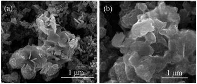 | ||
| Fig. 7 SEM images of the electrode for the Mn2O3/MnCr2O4 before (a) and after (b) 1000 cycles at 1 A g−1. | ||
Based on the above experimental results and analysis, we can infer that the following strategically interdependent characteristics of the Mn2O3/MnCr2O4 hybrid nanosheets are responsible for the outstanding LIBs performance. The nanosheets structure can effectively withstand the mechanical stress during the charge–discharge processes. Further more, the interconnected nanosheets and porous structure facilitates quick transmission channels for Li+ and electrons among active materials, and can also protect the stable structure from collapse and aggregation so as to reduce the resistance. Therefore, both the poor conductivity and volume changes of the Mn2O3/MnCr2O4 electrode can be circumvented by the as-prepared Mn2O3/MnCr2O4 hybrid nanosheets, which is beneficial for directing other multiphase TMOs electrode designs.
4. Conclusions
In conclusion, the Mn2O3/MnCr2O4 hybrid nanosheets have been successfully prepared from a facile synthesis approach by thermal decomposition of the Mn–Cr binary hydroxides and carbonate hybrid precursor. The special structure was designed simultaneously to enable the effective restriction of the volumetric expansion of the Mn2O3/MnCr2O4 as well as provide good electron and ion transport capability based on electrochemical impedance spectra. The electrochemical measurements demonstrate that the Mn2O3/MnCr2O4 electrode delivers an excellent reversible capacity of 913 mA h g−1 at a current density of 1 A g−1 after 300 cycles and excellent rate performance. The facile and scalable approach to fabricate the Mn2O3/MnCr2O4 hybrid nanosheets can expand the scope of the design concept of multiphase TMOs for LIBs application.Conflicts of interest
There are no conflicts to declare.Acknowledgements
This work is supported by the Emerging Strategic Industrial Science and Technology Project of Hunan province, China (2016GK4020), the National Natural Science Foundation of China (No. 51404041), and the Natural Science Foundation of Hunan province, China (No. 2018JJ2513).References
- C. P. Grey and J. M. Tarascon, Nat. Mater., 2016, 16, 45–56 CrossRef PubMed.
- S. Chu, Y. Cui and N. Liu, Nat. Mater., 2016, 16, 16–22 CrossRef PubMed.
- C. Zhang, Nat. Energy, 2017, 2, 17099 CrossRef.
- D. Vincent and L. Martiradonna, Nat. Mater., 2016, 16, 15 Search PubMed.
- Q. Liu, C. Du, B. Shen, P. Zuo, X. Cheng, Y. Ma, G. Yin and Y. Gao, RSC Adv., 2016, 6, 88683–88700 RSC.
- K. G. Gallagher, S. E. Trask, C. Bauer, T. Woehrle, S. F. Lux, M. Tschech, P. Lamp, B. J. Polzin, S. Ha, B. Long, B. Long, Q. Wu, W. Lu, D. W. Dees and A. N. Jansena, J. Electrochem. Soc., 2016, 163, A138–A149 CrossRef.
- Y. Wang, J. Roller and R. Maric, J. Power Sources, 2018, 378, 511–515 CrossRef.
- G. Zhao, X. Sun, L. Zhang, X. Chen, Y. Mao and K. Sun, J. Power Sources, 2018, 389, 8–12 CrossRef.
- P. Poizot, S. Laruelle, S. Grugeon, L. Dupont and J. M. Tarascon, Nature, 2000, 407, 496–499 CrossRef PubMed.
- S. Zhu, J. Li, X. Deng, C. He, E. Liu, F. He, C. Shi and N. Zhao, Adv. Funct. Mater., 2017, 27, 1605017 CrossRef.
- Z. Cao, M. Qin, B. Jia, L. Zhang, Q. Wan, M. Wang, A. A. Volinsky and X. Qu, Electrochim. Acta, 2014, 139, 76–81 CrossRef.
- Z. Bai, Y. Zhang, Y. Zhang, C. Guo, B. Tang and D. Sun, J. Mater. Chem. A, 2015, 3, 5266–5269 RSC.
- G. Zhang and X. W. Lou, Angew. Chem., Int. Ed., 2014, 126, 9187–9190 CrossRef.
- N. Wang, J. Yue, L. Chen, Y. Qian and J. Yang, ACS Appl. Mater. Interfaces, 2015, 7, 10348–10355 CrossRef PubMed.
- X. Liu, C. Zhao, H. Zhang and Q. Shen, Electrochim. Acta, 2015, 151, 56–62 CrossRef.
- Y. Xiang, H. Wu, K. H. L. Zhang, M. Coto, T. Zhao, S. Chen, B. Dong, S. Lu, A. Abdelkader, Y. Guo, Y. Zhang, S. Ding, K. Xi and G. Gao, J. Mater. Chem. A, 2017, 5, 8062–8069 RSC.
- S. Yuan, Y. Zhao, W. Chen, C. Wu, X. Wang, L. Zhang and W. Qiang, ACS Appl. Mater. Interfaces, 2017, 9, 21781–21790 CrossRef PubMed.
- H. Kong, C. Lv, C. Yan and G. Chen, Inorg. Chem., 2017, 56, 7642–7649 CrossRef PubMed.
- A. A. Abdelhamid, Y. Yu, J. Yang and J. Y. Ying, Adv. Mater., 2017, 29, 1701427 CrossRef PubMed.
- Y. Yuan, C. Zhan, K. He, H. Chen, W. Yao, S. Sharifiasl, B. Song, Z. Yang, A. Nie, X. Luo, H. Wang, S. M. Wood, K. Amine, M. S. Islam, J. Lu and R. Shahbazian-Yassar, Nat. Commun., 2016, 7, 13374 CrossRef PubMed.
- T. L. Nguyen, D. S. Kim, J. Hur, M. S. Park, S. Yoon and I. T. Kim, J. Power Sources, 2018, 389, 28–36 CrossRef.
- H. Tan, H. W. Cho and J. J. Wu, J. Power Sources, 2018, 388, 11–18 CrossRef.
- Z. Wang, Y. Cheng, Q. Li, L. Chang and L. Wang, J. Power Sources, 2018, 389, 214–221 CrossRef.
- P. Zheng, Y. Zhang, Z. Dai, Y. Zheng, K. N. Dinh, J. Yang, R. Dangol, X. Liu and Q. Yan, Small, 2018, 14, 1704065 CrossRef PubMed.
- S. Lu, T. Zhu, Z. Li, Y. Pang, L. Shi, S. Ding and G. Gao, J. Mater. Chem. A, 2018, 6, 7005–7013 RSC.
- G. Gao, Y. Xiang, S. Lu, B. Dong, S. Chen, L. Shi, Y. Wang, H. Wu, Z. Li, A. Abdelkader, K. Xi and S. Ding, Nanoscale, 2018, 10, 921–929 RSC.
- G. Gao, S. Lu, B. Dong, W. Yan, W. Wang, T. Zhao, C. Y. Lao, K. Xi, R. V. Kumar and S. Ding, J. Mater. Chem. A, 2016, 4, 10419–10424 RSC.
- G. Gao, S. Lu, Y. Xiang, B. Dong, W. Yan and S. Ding, Dalton Trans., 2015, 44, 18737–18742 RSC.
- J. Xu, H. Zhang, R. Wang, P. Xu, Y. Tong, Q. Lu and F. Gao, Langmuir, 2018, 34, 1242–1248 CrossRef PubMed.
- Y. Chen, Y. Wang, X. Shen, R. Cai, H. Yang, K. Xu, A. Yuan and Z. Ji, J. Mater. Chem. A, 2017, 6, 1048–1056 RSC.
- Y. Lu, J. Nai and X. W. Lou, Angew. Chem., Int. Ed., 2018, 57, 2899–2903 CrossRef PubMed.
- W. Wang, N. Wu, J. M. Zhou, F. Li, Y. Wei, T. H. Li and X. L. Wu, Nanoscale, 2018, 10, 6832–6836 RSC.
- L. Lu, Y. L. Gao, Z. Z. Yang, C. Wang, J. G. Wang, H. Y. Wang and Q. C. Jiang, J. Power Sources, 2018, 384, 256–263 CrossRef.
- H. Liu, Q. Li, Z. Yao, L. Li, Y. Li, C. Wolverton, M. C. Hersam, J. Wu and V. P. Dravid, Adv. Mater., 2017, 30, 1704851 CrossRef PubMed.
- X. Lin, K. Wu, L. Shao, M. Shui, X. Jiang, D. Wang, N. Long, Y. Ren and J. Shu, J. Alloys Compd., 2014, 598, 68–72 CrossRef.
- J. Zhou, S. Cheng, Y. Jiang, F. Zheng, X. Ou, L. Yang, M. Wang, M. Yao and M. Liu, RSC Adv., 2017, 7, 21214–21220 RSC.
- H. B. Lin, H. B. Rong, W. Z. Huang, Y. H. Liao, L. D. Xing, M. Q. Xu, X. P. Li and W. S. Li, J. Mater. Chem. A, 2014, 2, 14189–14194 RSC.
- Y. Zhang, Y. Yan, X. Wang, G. Li, D. Deng, L. Jiang, C. Shu and C. Wang, Chem.–Eur. J., 2014, 20, 6126–6130 CrossRef PubMed.
- X. Li, D. Li, L. Qiao, X. Wang, X. Sun, P. Wang and D. He, J. Mater. Chem., 2012, 22, 9189–9194 RSC.
- J. Yue, X. Gu, L. Chen, N. Wang, X. Jiang, H. Xu, J. Yang and Y. Qian, J. Mater. Chem. A, 2014, 2, 17421–17426 RSC.
- S. Khalid, C. Cao, M. Naveed and W. Younas, Sustainable Energy Fuels, 2017, 1, 1795–1804 RSC.
- Y. Deng, Z. Li, Z. Shi, H. Xu, F. Peng and G. Chen, RSC Adv., 2012, 2, 4645–4647 RSC.
- Y. Dai, H. Jiang, Y. Hu and C. Li, RSC Adv., 2013, 3, 19778–19781 RSC.
- C. Zhao, H. Zhang, W. Si and H. Wu, Nat. Commun., 2016, 7, 12543 CrossRef PubMed.
- J. Sun, K. Tang, X. Yu, J. Hu, H. Li and X. Huang, Solid State Ionics, 2008, 179, 2390–2395 CrossRef.
- L. Dupont, S. Laruelle, S. Grugeon, C. Dickinson, W. Zhou and J. M. Tarascon, J. Power Sources, 2008, 175, 502–509 CrossRef.
- J. Hu, H. Li, X. Huang and L. Chen, Solid State Ionics, 2006, 177, 2791–2799 CrossRef.
- Y. Chen, Z. Liu, S. P. Ringer, Z. Tong, X. Cui and Y. Chen, Cryst. Growth Des., 2007, 7, 2279–2281 CrossRef.
- D. Lenaz, H. Skogby, F. Princivalle and U. Hålenius, Phys. Chem. Miner., 2004, 31, 633–642 CrossRef.
- R. N. Bhowmik and R. Ranganathan, Phys. Rev. B: Condens. Matter Mater. Phys., 2006, 73, 144413 CrossRef.
- Y. Wang, W. Lai, N. Wang, Z. Jiang, X. Wang, P. Zou, Z. Lin, H. J. Fan, F. Kang, C. P. Wong and C. Yang, Energy Environ. Sci., 2017, 10, 941–949 RSC.
- J. Hu, H. Li and X. J. Huang, Electrochem. Solid-State Lett., 2005, 8, A66–A69 CrossRef.
- Q. Zhang, J. Wang, J. Dong, F. Ding, X. Li, B. Zhang, S. Yang and K. Zhang, Nano Energy, 2015, 13, 77–91 CrossRef.
- S. Zhu, J. Li, C. He, N. Zhao, E. Liu, C. Shi and M. Zhang, J. Mater. Chem. A, 2015, 3, 22266–22273 RSC.
- C. Zhu, R. E. Usiskin, Y. Yu and J. Maier, Science, 2017, 358, 1400 CrossRef PubMed.
- F. Wang, W. Li, M. Hou, C. Li, Y. Wang and Y. Xia, J. Mater. Chem. A, 2014, 3, 1703–1708 RSC.
- W. Zhang, J. Li, J. Zhang, J. Sheng, T. He, M. Tian, Y. Zhao, C. Xie, L. Mai and S. Mu, ACS Appl. Mater. Interfaces, 2017, 9, 12680–12686 CrossRef PubMed.
- J. T. Li, V. Maurice, J. Swiatowska-Mrowiecka, A. Seyeux, S. Zanna, L. Klein, S. G. Sun and P. Marcus, Electrochim. Acta, 2009, 54, 3700–3707 CrossRef.
- Y. Zeng, L. F. Li, H. Li, X. J. Huang and L. Q. Chen, Ionics, 2009, 15, 91–96 CrossRef.
- H. Sun, G. Xin, T. Hu, M. Yu, D. Shao, X. Sun and J. Lian, Nat. Commun., 2014, 5, 4526 CrossRef PubMed.
- Y. Y. Hu, Z. Liu, K. W. Nam, O. J. Borkiewicz, J. Cheng, X. Hua, M. T. Dunstan, X. Yu, K. M. Wiaderek, L. S. Du, K. W. Chapman, P. J. Chupas, X. Q. Yang and C. P. Grey, Nat. Mater., 2013, 12, 1130–1136 CrossRef PubMed.
Footnote |
| † Electronic supplementary information (ESI) available. See DOI: 10.1039/c8ra04868a |
| This journal is © The Royal Society of Chemistry 2018 |

