 Open Access Article
MOF derived carbon based nanocomposite materials as efficient electrocatalysts for oxygen reduction and oxygen and hydrogen evolution reactions
Sohini
Bhattacharyya
 ,
Chayanika
Das
and
Tapas Kumar
Maji
 *
*
Molecular Materials Laboratory, Chemistry and Physics of Materials Unit, School of Advanced Materials (SAMat), Jawaharlal Nehru Centre for Advanced Scientific Research (JNCASR), Bangalore, India. E-mail: tmaji@jncasr.ac.in
First published on 26th July 2018
Abstract
The escalating global energy demands and the formidable risks posed by fossil fuels coupled with their rapid depletion have inspired researchers to embark on a quest for sustainable clean energy. Electrochemistry based technologies, e.g., fuel cells, Zn–air batteries or water splitting, are some of the frontrunners of this green energy revolution. The primary concern of such sustainable energy technologies is the efficient conversion and storage of clean energy. Most of these technologies are based on half-cell reactions like oxygen reduction, oxygen and hydrogen evolution reactions, which in turn depend on noble metal based catalysts for their efficient functioning. In order to make such green energy technologies economically viable, the need of the hour is to develop new noble metal free catalysts. Porous carbon, with some assistance from heteroatoms like N or S or earth abundant transition metal or metal oxide nanoparticles, has shown excellent potential in the catalysis of such electrochemical reactions. Metal–organic frameworks (MOFs) containing metal nodes and organic linkers in an ordered morphology with inherent porosity are ideal self-sacrificial templates for such carbon materials. There has been a recent spurt in reports on such MOF-derived carbon based materials as electrocatalysts. In this review, we have presented some of this research work and also discussed the practical reasons behind choosing MOFs for this purpose. Different approaches for synthesizing such carbonaceous materials with unique morphologies and doping, targeted towards superior electrochemical activity, have been documented in this review.
1. Introduction
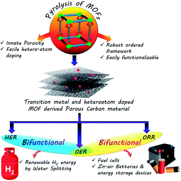
The rapid progress in technology and industrialization has caused an enormous increase in global energy requirement. To date, the world relies almost entirely on non-renewable fossil fuels to cater to the daily energy requirements.1 However, the immense adverse effects caused by these fossil fuels on the environment in the form of global warming as well as their swift depletion rates makes it essential for us to regulate their use immediately.2–4 Thus the world is in the process of a gradual shift towards a renewable energy based economy, namely solar, wind, and hydro power.5–9 However, these sources do not always ensure a steady flow of power and are often sporadic in their outputs. The efficient usage of such sources thus requires effective assistance from conversion and storage technologies such as fuel cells, batteries and capacitors.10–19 Fuel cells and metal–air batteries are typical representatives of energy conversion and storage systems with high energy density, high efficiency and no greenhouse emissions.20–33 The competence of these devices is primarily determined by the functional materials used as electrocatalysts in their components. Thus the major concern of scientists worldwide is the development of cost and energy efficient sustainable electrocatalysts for better conversion, storage and utilization of renewable energy. While fuel cells involves the combination of a steady stream of O2 at the cathode and H2 at the anode to form water, regenerative fuel cells rely on the reverse process of splitting water to generate O2 and H2.18,32,34–38 The former is concerned mainly with oxygen reduction reaction (ORR) at the cathode and hydrogen oxidation reaction (HOR) at the anode, and the latter includes hydrogen and oxygen evolution reactions (HER and OER, respectively). Similarly, metal–air batteries perform OER while charging and ORR during discharging cycle.20,22–25,30,31,39–45 Many of the above mentioned electrochemical reactions are extremely sluggish in nature, making the use of catalysts mandatory. However, the most efficient catalysts for these processes are often expensive and scarce noble metals like Pt, Ir and Ru.45–61 The exorbitant prices of these metals are the biggest obstacles hindering the widespread commercialization of electrochemical process dependant energy technologies. Hence one of the biggest challenges of the materials science world currently involves the development of low-cost, sustainable, energy efficient functional materials that can compete with these noble metals in their activity and thereby replace them. The alternative materials envisaged for this purpose are carbon based materials or benign earth abundant metal based counterparts.27–29,57–75 An absolute necessity in these materials is the presence of easily accessible redox-active centres, that will trap the particular element and reduce them promptly. Hence redox active, semiconducting, porous materials like MOFs, COFs or CMPs seem to be the ideal candidates for such catalysis.64,124,166,167 Among the cost-effective catalysts explored in recent times, porous carbon materials have emerged as one of the flag bearers owing to their stability, high conductivity, excellent surface area, tunable porosity and surface chemistry.64 A few recent reports have also exhibited the efficacy of doping heteroatoms (e.g., N, S and B) in a porous carbon matrix in elevating electrocatalytic activity. These heteroatoms are present in the carbon matrix as defects and brings about electronic and structural modifications (Scheme 1).65–75One of the most celebrated functional materials of the past decade has been Metal–organic frameworks (MOFs) comprising ordered arrays of metal nodes connecting organic linkers.76–79 MOFs have clinched the attention of chemists owing to their light weight, low density, ultra high surface area, porosity and tunable pore surface. Traditionally, MOFs have found application in gas separation, storage and capture of specific molecules.80–85 They have also been utilized for catalysis, sensing and for various optoelectronic applications.85–90 Of late, MOFs and their derivatives have been explored as electrocatalysts. MOFs, owing to their innate porosity, large carbon content and ordered structures are the ideal templates for porous carbon based materials. Many of the recent research work on electrocatalysis have upheld MOFs and their derived materials as efficient electrocatalysts. In this review, we have documented some of them which stand out and establish that the tailored synthesis of MOFs and their derived materials can provide some of the best materials for electrocatalysis. For this purpose, we have first discussed the design principles of such materials, followed by their activity in common electrochemical processes, e.g., ORR, HER, OER and also bifunctional activity. The systematic arrangement in this review will hopefully be helpful to researchers working in this field and in the future it will help towards the development of supreme MOF-derived carbon based electrocatalysts.
2. Why MOFs as templates for porous carbon based electrocatalysts?
Taking a step away from the conventional applications of MOFs, e.g., storage and separation of gases, drug delivery, magnetism and optoelectronics, recent research has been aimed at designing MOF based electrocatalysts. The easily tunable pore structures and accessible metal nodes are the biggest advantages of using MOFs as electrocatalysts. The permanent porosity of MOFs helps in the swift diffusion of substrates throughout the material, thus helping the substrates reach catalytic sites comfortably. By careful selection of metal and linkers and altering the stoichiometry, one can achieve structures that have supreme electrochemical activity. Frameworks containing earth abundant redox-active first row transition metals (e.g., Fe, Co, Ni, Mn, etc.) are particularly suitable for the job. Upon being coupled with a redox active linker, MOFs can show excellent electrochemical activity.168 Moreover the isolated metal nodes in MOFs enclosing nanoconfines are ideal for molecular catalysis. In spite of several advantages, the biggest drawback in using MOFs as electrocatalysts is their poor conductivity that limits the electrochemical activity.91 The most common way to counter this is to introduce catalytic nanoparticles or conductive guest species in the pores of the MOF, e.g., TCNQ or TTF.92 Sometimes the formation of composites with highly conductive materials like graphene is also advantageous.169 A composite of a Zr-MOF, NU-1000 with Ni–S films has shown excellent activity as a catalyst for HER.93 Growing MOFs as thin films is another strategy for generating productive electrocatalysts, as the control over film thickness is crucial to facilitate electron transport through the active catalytic sites. Yang et al. used thin films of Co–porphyrin nanoMOF for the electrochemical reduction of CO2.94 However, the most effective strategy to fabricate electrocatalysts from MOFs is the synthesis of MOF derived carbonaceous materials.Porous carbon when doped with heteroatoms, e.g., N, S or B, have been reported to show enhanced electrocatalytic activities, comparable to some of the noble metal-based benchmark catalysts. Also, non-precious metal and metal oxide nanoparticles (NPs) supported on carbon matrix (MNPC) with high porosity offer numerous exposed and easily accessible active sites, thereby improving overall electrocatalytic activity.67,68,70,75,95,96 However, the traditional methods for synthesis of such porous carbon materials involves simple pyrolysis followed by physical or chemical activation of organic precursors, which often gives rise to highly disordered structures with broad pore size distribution. This paved the way for nanocasting or templating approaches, initiated using soft templates, e.g., resols and hard templates, e.g., zeolites.97,98 These were again found to be unsuitable for bulk scale production. In an innovative approach, Xu et al. first proposed MOFs as self sacrificial templates for effective synthesis of porous carbon.91 The inherent porosity of MOF, high surface area, large carbon content and ordered structure makes them ideal candidates as templates for carbon materials. They also ensure facile heteroatom and metal doping in the carbon matrix, thereby producing novel materials with enhanced properties. In many cases, precursors like furfuryl alcohol, sucrose, glycerol, phenolic resin, etc. are introduced in the MOF templates as a carbon source. However, it is also possible to make such materials without the use of any external precursor and the original MOF linker is treated as a source for carbon as well as heteroatoms like N or S. Because of their electron rich surfaces, such heteroatom doped carbon materials have the potential to manifest excellent electrocatalytic activity. In addition, if the original electroactive metal atom of the MOF is retained in the form of metal or metal oxide nanoparticles, the electrochemical activity can be further enhanced.
To put it in layman's terms, electronic properties of a particular material dictates its efficiency as an electrocatalyst.99,100 A pure graphitic carbon matrix consisting of sp2 bonded carbon atoms with an uniformly delocalized electron cloud lacks polarization and consequently cannot afford to accommodate a foreign electronic cloud of intermediates.101 Heteroatoms, e.g., N, B, P or S, with different electronegativities when introduced into this graphitic matrix, a redistribution of the electronic cloud takes place, thereby creating a polarization which can now accommodate the foreign invasion of intermediates.102,103 The most commonly doped heteroatom is nitrogen which is more electronegative and hence these doping sites are potent for metal/functional group coordination and act as active sites for the electrocatalysis.99,100 The heteroatom doped carbon matrix have the potential to act as efficient metal free electrocatalysts.104–111 One of the primary reasons to choose MOFs as templates for carbonization is the ease of including heteroatoms in the carbon matrix, by simply selecting a MOF with a heteroatom containing linker. For example, MOFs with imidazolate framework are often pyrolyzed at inert atmosphere to get N-doped carbon matrix with large surface area.112–119 Muhler et al. showed the formation of core–shell Co@Co3O4 nanoparticles embedded in carbon nanotubes (CNTs) by the direct carbonization of ZIF-67, a Co imidazolate framework120 (Fig. 1(b)). Other N-containing linkers, e.g., pyridine derivatives may also be used. We showed the formation for Co doped carbon nanotubes (Co-CNTs) by the pyrolysis of dicyanamide based nitrogen rich MOF {[Co(bpe)2(N(CN)2)]·(N(CN)2)·(5H2O)}n [Co-MOF-1, bpe=1,2-bis(4-pyridyl)ethane, N(CN)2− = dicyanamide].121 However, in most cases, scientists opt for external N-sources like urea, melamine, etc. to generate N containing C materials. Kurungot et al. performed the pyrolysis MOF5 in the presence of nitrogen rich melamine to generate g-C3N4 for electrocatalytic ORR (Fig. 1(a)).122 Guest molecules impregnated within the MOF pores may also be used as a source of heteroatom.119,123–128 In an interesting piece of work, we have utilized a guest dimethyl amine cation of an anionic MOF as a pre-bonded C–N–C moiety to generate N-doped C-dots.129 Also, co-doping two or more elements with reverse electronegativity results in greater number of defects, generating more number of active sites for an elevated electrocatalytic activity. Thus, compared to single heteroatom doping, multiple heteroatom doping could be beneficial. For this, either the ligand must be selected such that it has the choice of heteroatoms or the MOF can be impregnated with heteroatom containing moieties.
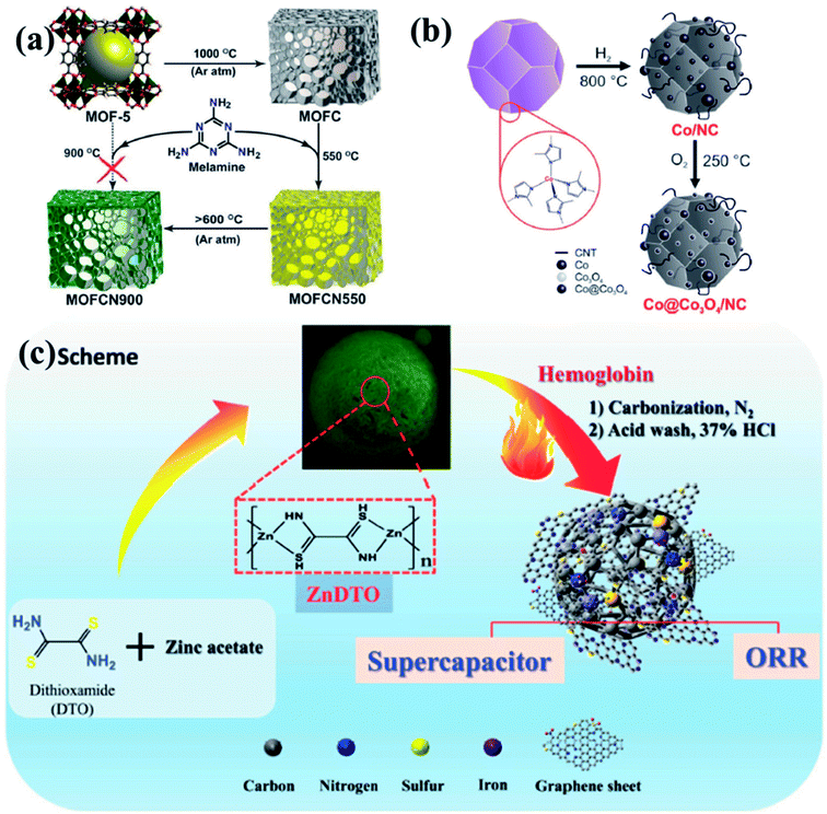 | ||
| Fig. 1 (a) Schematic representation of generation of graphitic carbon nitride from MOF5 using melamine as a precursor. Reproduced with permission from ref. 122. Copyright 2014 American Chemical Society. (b) Synthesis of Co@Co3O4/NC from ZIF-67 by tuning the annealing temperature and atmosphere. Reproduced with permission from ref. 120. Copyright 2016 Wiley. (c) Doping of Fe, N and S in the carbon matrix using a 1D ZnDTO coordination polymer. Reproduced with permission from ref. 158. Copyright 2017 Wiley. | ||
It has already been established that metals/metal oxides and their nanoparticles (NPs) play an integral role in the electrocatalysis.46,50,52,59,130,131 The more recent literature presents that metal/metal oxide NPs encapsulated inside carbon matrix are also effective in improving the electrocatalytic activity.54,67,95,132,133 MOFs, containing redox-active metal nodes and carbon rich organic ligands thus become the automatic choice of sacrificial templates for preparing metal NPs embedded in a carbon matrix. Introduction of more than one transition metal in the matrix has also been proven beneficial in enhancing the electrocatalytic activity.134–137 Post-synthetic metal exchanged MOF, metal cores coated with MOF, bimetallic MOFs are some of the possible sacrificial precursor for the preparation of multiple transition metal electrocatalysts.134,135,138,139 Depending upon the carbonization atmosphere, encapsulations and type of post treatments, metal carbides, nitrides, oxides, sulphides or phosphides are formed. Shim et al. pyrolysed an 1D coordination polymer synthesized from Zn and dithiooxamide linker doped with hemoglobin to generate Fe, S and N doped carbon matrix (Fe-SNC) which showed excellent activity as a supercapacitor and electrocatalyst for ORR (Fig. 1(c)).158
Morphology of the MOF or the derived material also plays a crucial role in determining its electrochemical activity. The porosity of the composite depicts the active site accessibility and consequently the efficacy. However, high temperature annealing sometimes causes the framework to shrink and lose porosity, surface area and active site accessibility. Although this may be addressed by controlling the annealing temperature, however there is no clear solution to counter it and thus morphology control still remains a challenge. An effective and desirable electrocatalyst should have highly accessible active catalytic sites, facile electron transfer all over the matrix in order to get good conductivity and usage of earth abundant transition metals to curtail cost. A cautious balance of these features is the key to generate effective electrocatalysts for sustained use. In summary, MOFs are one of the best suited templates for the generation of such porous carbon based matrices for electrochemical applications because of the following reasons:
(a) The nanocasting approach of using MOF templates is extremely effective because of the ordered structure and innate porosity. Thus MOFs ensure facile encapsulation of carbon or heteroatom containing guest species.
(b) The various nanoscale morphologies of MOFs ensure similar morphologies in their carbon counterparts, exposing active sites.
(c) MOFs can be efficiently grown over conductive surfaces or substrates as nanomorphologies or thin films, ensuring better activity.
In the following paragraphs, few electrocatalysts prepared using the above strategies are discussed categorically as ORR, OER, HER and bifunctional catalysts.
3. MOF derived carbon nanocomposites in ORR, OER and HER
3.1 MOF derived materials for oxygen reduction reaction (ORR)
Reduction of oxygen is not only one of the most important reactions in animal physiology, but also important industrially, particularly in fuel cells and metal–air batteries. In this process, oxygen may either gain two electrons to form H2O2 or four electrons to form H2O. The kinetics of this reaction is extremely sluggish in nature and requires catalysts for its progress. Till date, the best known catalyst for this has been platinum, which because of its scarcity and immense expenses, has kept all attempts of commercializing ORR based technologies at bay. Thus over the past few decades, one of the major topics of research in materials science has been the incessant quest for cheaper, sustainable, environmentally benign catalyst for ORR. Some of the nanoporous carbons have shown tremendous potential as electrocatalysts for ORR. As mentioned previously, heteroatom doping plays an important role in creating defects in the carbon matrix which in turn reflects in the improvement of the catalytic activity.The most common approach to prepare N-doped MOF derived electrocatalyst is to select a MOF with a N-rich ligand, viz., imidazole (IM), in particular the ZIF series of MOFs. You et al. showed that direct pyrolysis of ZIF-67 (Co(MIM)2, MIM = methylimidazole) produced a highly N-doped carbonaceous material with Co impregnation.156 Metal free, N-doped porous carbon material was prepared by Cao and group where they treated ZIF-7 (Zn(PhIM)2·(H2O)3; PhIM = benzimidazole) with glucose as an external excess carbon source.140 The carbonized material was tested as an electrocatalyst for ORR and it showed an onset potential of 0.7 V vs. RHE, selective H2O production without any methanol crossover effect.
A series of bimetallic ZIFs (BMZIFs) with varied Zn/Co ratio were also studied for preparation of porous carbon materials where N was doped uniformly by Jiang and group (Fig. 2(a)).141 Zn got evaporated leaving Co decorated N-doped carbon matrix (CNCo-n) (n indicating the Zn/Co molar ratio in the precursor BMZIF). Later CNCo-n was doped with P by annealing it with triphenylphosphine under N2 atmosphere (Fig. 2(b–d)). CNCo-20 when studied as an ORR electrocatalyst showed an onset potential of −0.08 vs. Ag/AgCl, on P-doping (P–CNCo-20) the onset potential shifted towards more positive potential (−0.04 V vs. Ag/AgCl) (Fig. 2(e–g)). These catalysts also showed long term stability and good methanol tolerance. Tang and co-workers post-synthetically treated a Co-MOF (ZIF-67) with NiCl2 solution to get Ni/Co-MOF which on pyrolysis transformed into a highly porous carbon matrix with uniformly distributed Co, Ni and N centres, ensuring a high density of active sites with superior ORR activity in electrolytic solution of neutral to higher pH.142
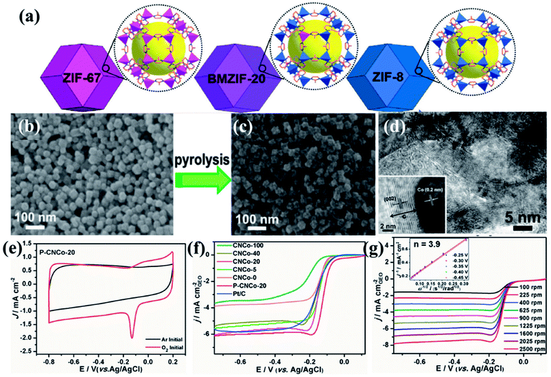 | ||
| Fig. 2 (a) Schematic representation of the imidazole based frameworks used for carbonization. SEM images of (b) BMZIF-20 and its pyrolysed counterpart (c) CNCo-20. (d) TEM image showing Co nanoparticles embedded in layers of graphitized carbon. (e) CV of P–CNCo-20 in 0.1 M KOH in Ar and O2 saturated conditions. (f) LSV curves for the different carbonized samples in 0.1 M KOH at 1600 rpm. (g) LSV curves at different rotation speeds for P–CNCo-20 in 0.1 M KOH. Reproduced with permission from ref. 141. Copyright 2015 Wiley. | ||
Carbonization of self-adjusted Zn and Co bimetal–organic frameworks (bi-MOF) [ZnxCo1−x(MeIM)2; MeIM = methyl imidazole] resulted in Co–N–C-x composites. Among these materials, Co–N–C-0.8 was found to be the most active toward the ORR due to the presence of pyridinic N (47%), pyrrolic N (43%), and oxidized N (10%) in the carbon matrix.143
In an attempt to understand the effect of annealing temperature on the morphology of MOF derived materials, recently our group documented synthesis of nanoporous carbon and nitrogen doped carbon dots from Mg(II) based anionic MOF (Mg-MOF) {[Mg3(ndc)2.5(HCO2)2(H2O)]·[NH2Me2]·2H2O·DMF} (ndc = naphthalene dicarboxylate) by varying the carbonizing temperature.129 The nanoporous carbon (NPC) obtained by carbonizing Mg-MOF at 900 °C and subsequently washing with a concentrated acid mixture (HCl![[thin space (1/6-em)]](https://www.rsc.org/images/entities/char_2009.gif) :
:![[thin space (1/6-em)]](https://www.rsc.org/images/entities/char_2009.gif) HNO3 in 1
HNO3 in 1![[thin space (1/6-em)]](https://www.rsc.org/images/entities/char_2009.gif) :
:![[thin space (1/6-em)]](https://www.rsc.org/images/entities/char_2009.gif) 1 v/v). N-doped carbon dots (NCD) were obtained at 500 °C by treating in similar conditions (Fig. 3(a)). Both NPC and NCD were characterized by IR, Raman, XPS, XRD and several microscopic techniques. NPC showed BET surface area of 3690 m2 g−1, which is one of the highest surface areas of a porous carbon obtained from directly carbonizing a MOF. The presence of DMA (NH2Me2) containing prebonded C–N moieties in the pore of the anionic Mg-MOF helped in the synthesis of N-doped carbon dots. The diameter of each dot is well below 10 nm and HRTEM showed graphitic lattice fringes with an inter planar distance of 0.34 nm (Fig. 3(b)). Surface area of NCD is about 95 m2 g−1. NCD has structural and compositional features similar to g-C3N4 which is known to show good catalytic activity for ORR. Linear sweep voltammetry (LSV) at different rotation speeds was performed and NCD showed moderate catalytic activity for ORR (Fig. 3(c)). To further improve the catalytic activity, Co atoms were doped in the NCD. This was achieved by mixing Co–porphyrin with NCD and the mixture was pyrolized at 800 °C and a new composite was obtained. PXRD, XPS and TEM analysis suggest the presence of metallic Co-nanoparticle on the N-doped graphitic carbon (Fig. 3(e)). XRD also suggested the tris-s-triazine units in carbon nitride, remain intact after Co-doping. TEM study showed that metallic Co-nanoparticles (less than 5 nm) embedded in a carbon matrix and lattice spacing of 0.24 nm corresponded to fcc Co. ICP analysis suggested about 1.5 wt% of Co in the Co@CN nanocomposite material. ORR activity was studied using Co@CN sample and a significant difference was observed with respect to NCD. LSV of Co@CN showed significantly enhanced cathodic current as a function of rotation speed and affording a current density of −1 mA cm−2 at low overpotentials (∼0.8 V) as compared to 0.36 V for NCD (Fig. 3(f)). K–L plot revealed that linearity and the number of electrons transferred during the ORR is 3.87, suggesting 4 electron transfer pathway to produce H2O after O2 reduction. Further, rotating ring disk electrode (RRDE) measurement showed that H2O2 production is decreased from 40.8% for NCD to 2.3% for Co@CN (Fig. 3(d)). The Tafel slopes for Co@CN were 63 mV per decade and 141 mV per decade at lower and higher current density respectively, suggesting faster reaction kinetics. Chronopotentiometric (CP) electrolysis study were performed for both NCD and Co@CN at a constant voltage for 48 h at a rotation speed of 1600 rpm (Fig. 3(g)). Both the catalysts showed excellent stability in alkaline solution during ORR. Overall, these results demonstrated that NCD catalyze the reduction of O2 to H2O2 and metallic Co-nanoparticles catalyze the decomposition of the formed H2O2. Such enhanced catalytic activity in Co@CN can be attributed to the electronic interaction between the metal nanoparticles and graphitic carbon, which accelerates the kinetics of the ORR.
1 v/v). N-doped carbon dots (NCD) were obtained at 500 °C by treating in similar conditions (Fig. 3(a)). Both NPC and NCD were characterized by IR, Raman, XPS, XRD and several microscopic techniques. NPC showed BET surface area of 3690 m2 g−1, which is one of the highest surface areas of a porous carbon obtained from directly carbonizing a MOF. The presence of DMA (NH2Me2) containing prebonded C–N moieties in the pore of the anionic Mg-MOF helped in the synthesis of N-doped carbon dots. The diameter of each dot is well below 10 nm and HRTEM showed graphitic lattice fringes with an inter planar distance of 0.34 nm (Fig. 3(b)). Surface area of NCD is about 95 m2 g−1. NCD has structural and compositional features similar to g-C3N4 which is known to show good catalytic activity for ORR. Linear sweep voltammetry (LSV) at different rotation speeds was performed and NCD showed moderate catalytic activity for ORR (Fig. 3(c)). To further improve the catalytic activity, Co atoms were doped in the NCD. This was achieved by mixing Co–porphyrin with NCD and the mixture was pyrolized at 800 °C and a new composite was obtained. PXRD, XPS and TEM analysis suggest the presence of metallic Co-nanoparticle on the N-doped graphitic carbon (Fig. 3(e)). XRD also suggested the tris-s-triazine units in carbon nitride, remain intact after Co-doping. TEM study showed that metallic Co-nanoparticles (less than 5 nm) embedded in a carbon matrix and lattice spacing of 0.24 nm corresponded to fcc Co. ICP analysis suggested about 1.5 wt% of Co in the Co@CN nanocomposite material. ORR activity was studied using Co@CN sample and a significant difference was observed with respect to NCD. LSV of Co@CN showed significantly enhanced cathodic current as a function of rotation speed and affording a current density of −1 mA cm−2 at low overpotentials (∼0.8 V) as compared to 0.36 V for NCD (Fig. 3(f)). K–L plot revealed that linearity and the number of electrons transferred during the ORR is 3.87, suggesting 4 electron transfer pathway to produce H2O after O2 reduction. Further, rotating ring disk electrode (RRDE) measurement showed that H2O2 production is decreased from 40.8% for NCD to 2.3% for Co@CN (Fig. 3(d)). The Tafel slopes for Co@CN were 63 mV per decade and 141 mV per decade at lower and higher current density respectively, suggesting faster reaction kinetics. Chronopotentiometric (CP) electrolysis study were performed for both NCD and Co@CN at a constant voltage for 48 h at a rotation speed of 1600 rpm (Fig. 3(g)). Both the catalysts showed excellent stability in alkaline solution during ORR. Overall, these results demonstrated that NCD catalyze the reduction of O2 to H2O2 and metallic Co-nanoparticles catalyze the decomposition of the formed H2O2. Such enhanced catalytic activity in Co@CN can be attributed to the electronic interaction between the metal nanoparticles and graphitic carbon, which accelerates the kinetics of the ORR.
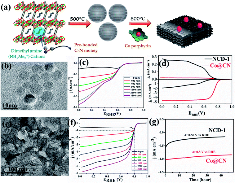 | ||
| Fig. 3 (a) Schematic representation of the pyrolysis of 1 at 500 °C to generate N-doped C-dots and further Co doping in it. (b) TEM image of the N-doped C-dots formed by carbonizing 1. (c) LSV curves for ORR by NCD-1. (d) RRDE voltammograms collected at 5 mV s−1 and 1600 rpm showing ORR in 0.1 M KOH. (e) TEM image of Co@CN. (f) LSV curve for ORR in 0.1 M KOH for Co@CN. (g) Chronoamperometric response for NCD-1 and Co@CN. Reproduced from ref. 129. Copyright 2017 Royal Society of Chemistry. | ||
A similar attempt by Liang et al., yielded N and S doped mesoporous carbon by annealing an inherently N and S containing MOF [Zn2(TDC)2(DABCO)]·4DMF (SCUT-12, TDC = 2,5- thiophenedicarboxylic acid, DABCO = 1,4-diazabicyclo[2.2.2]octane) without the use of any external dopant. Owing to different pyrolysis temperatures, the S content and type varied, giving different ORR activities. Overall the material showed excellent ORR activity comparable to Pt/C catalyst.144
Zou and co-workers studied the effect of particle size of nano MOF and the corresponding derived material on the catalytic activity.145 They synthesized ZIF-67 (Fig. 4(a)) in various conditions to achieve different particle sizes ranging from bulk to 300 nm. The polyhedral morphology of the MOF nanoparticles were retained in the MOF derived carbon materials (MDCs) by carefully choosing the pyrolyzing temperature under Ar atmosphere, which is ascertained from TEM and SEM studies (Fig. 4(b and c)). TEM also proves the presence of Co in the carbon matrix (Fig. 4(c)). The effect of size of the particles directly affects the electrocatalytic activity, as observed by recording the LSV curves for the different samples (Fig. 4(d)). The LSV shows a lesser overpotential for onset of ORR (0.86 V vs. RHE) for the lowest size MDC (300 nm) than for the MDC derived from bulk MOF (0.80 V vs. RHE). The electron transfer pathway was also affected by the particle size, as the 300 nm MDC shows 4-electron transfer with the highest stability (Fig. 4(e)). This study establishes that with smaller particle size, the active sites are much more exposed and easily accessible which promotes faster mass and electron transfer.
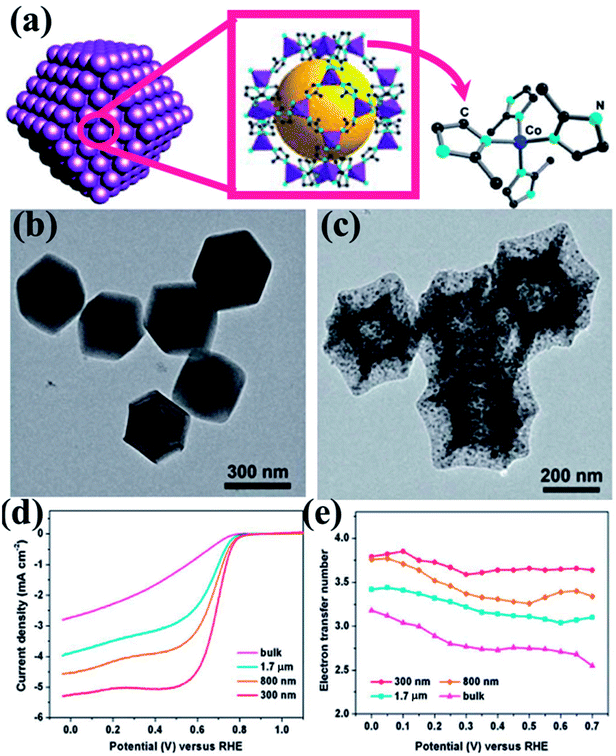 | ||
| Fig. 4 (a) Schematic representation of ZIF-67 nanopolyhedrons. (b) Polyhedral morphology of the ZIF-67 as seen under TEM. (c) TEM image showing preservation of polyhedral morphology after annealing at 750 °C. (d) RDE polarization curves of 300 nm, 800 nm, 1.7 mm and bulk MDCs in 0.1 M HClO4 at a rotation rate of 1600 rpm; (e) the electron transfer number as a function of potential for MDCs with various sizes. Reproduced with permission from ref. 145. Copyright 2014 Royal Society of Chemistry. | ||
The effect of morphology on electrochemical activity was presented in an intriguing work by Yu et al.,146 where tellurium nanowires (TeNWs) were used as templates for growing ZIF-8 nanofibers (Fig. 5(a and b)). Carbonization of the resultant high aspect ratio ZIF-8 nanofibers at 1000 °C yields highly porous N-doped carbon nanofibers (Z8-Te-1000) which retain the hollow fibrous morphology with uniform diameter of 50 nm (Fig. 5(c)). The electrocatalytic activity of Z8-Te-1000 was primarily shown in the CVs recorded in O2 and N2 saturated 0.1 M KOH solution separately (Fig. 5(d)). The Z8-Te-1000 showed good catalytic activity towards ORR which is apparent from the LSVs recorded at different rotation speeds and the corresponding K–L plot (Fig. 5(e,f)). To further increase the catalytic activity reannealing with triphenylphosphine was done which resulted in P-doping (P-Z8-Te-1000). P-Z8-Te-1000 shows excellent activity as an electrocatalyst for ORR, even superior to the benchmark Pt/C catalyst (Fig. 5(g)). However, the carbon material obtained by the direct pyrolysis of bulk ZIF-8 does not show good electrocatalytic activity (Fig. 5(g)).
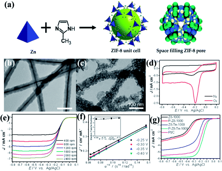 | ||
| Fig. 5 (a) Representation of ZIF-8 unit cell and space filling pore of ZIF-8. Reproduced from ref. 161. TEM images of (b) Te@ZIF-8 with average diameter of 45 nm (c) Z8-Te-1000 showing hollow fibrous morphology. (d) CVs of P-Z8-Te-1000 in O2 and N2 saturated 0.1 M KOH; (e) LSVs of P-Z8-Te-1000 recorded at different rotation rates and at a scan rate of 10 mV s−1; (f) Koutecky–Levich plots of P-Z8-Te-1000 derived from LVSs at different rotation speed; (g) LSVs of all the catalysts in O2 saturated 0.1 M KOH with a sweep rate of 10 mV s−1 and electrode rotation speed of 1600 rpm. Reproduced with permission from ref. 146. Copyright 2014 American Chemical Society. | ||
A remarkable piece of work by Yu et al., utilizes the bifunctionality observed in a MOF-derived porous carbon for direct use in Zn–Air and Li–S batteries. In this case, a dual templating approach was followed where initially an ordered silica photonic crystal template was produced from 200 nm silica particles, followed by the infiltration by ZIF-8 precursor solution (Fig. 6(a)). Complete solvent evaporation yields uniform ZIF-8 crystals on the silica microsphere surface and in the interstitial voids (Fig. 6(b)). Next pyrolysis at high temperature of (800–1100 °C) converted the composite into carbon morphologies supported on a silica matrix (Fig. 6(c)). A macroporous carbon texture with interconnected narrow walls between the special voids was obtained upon removing the silica matrix (Fig. 6(d)). The sample carbonized at 950 °C (BHPC-950) has a high total pore volume of 13.42 cm3 g−1, large specific surface area of 2546 m2 g−1 and a high nitrogen dopant content of 7.6 atom%. BHPC-950 shows an excellent ORR activity with an onset potential of 0.93 V and a limiting current density of 5.34 mA cm−2 and a 4-electron pathway (Fig. 6(e)). Not only does it surpass the benchmark Pt/C catalyst in its activity, but also it shows a very small Tafel slope of 74 mV dec−1, signifying a large number of exposed active sites and swift ORR kinetics. However, a sample prepared by the direct carbonization of ZIF-8 nanocrystals under the same conditions without macropores does not show appreciable ORR activity. Since both the samples have equivalent N content, the reduced activity can only be attributed to the low specific surface area, due to the lack of macropores, less number of exposed sites and high mass-transfer barrier. BHPC-950 was assembled by loading on carbon cloth as an air cathode along with a Zn-foil as the anode in a Zn–air battery. BHPC-950 shows a high discharge current density of 319 mA cm−2 and peak power density of 197 mW cm−2 at catalyst loading of merely 0.5 mg cm−2 (Fig. 6(f)). The BHPC-950 battery shows a specific capacity of 797 mA h gZn−1 corresponding to an energy density of 963 W h kgZn−1 at 20 mA cm−2, which corresponds to 95% utilization of theoretical capacity. The outstanding stability of BHPC-950 electrode is exhibited by the continuous lighting of a LED pattern comprising 30 2.2 V LED bulbs by two such Zn–air batteries in series for more than 12 h without brightness decay (Fig. 6(g)).147
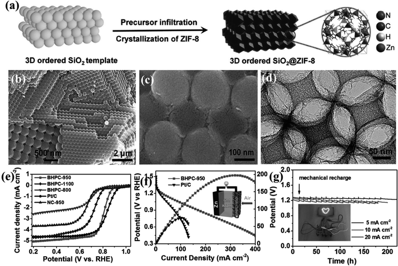 | ||
| Fig. 6 (a) Schematic representation of growing ZIF-8 crystals on an ordered silica template. SEM image of silica template with ZIF-8 nanocrystals (b) before and (c) after carbonization. (d) HRETM image of the carbonized sample after etching the silica template. (e) LSV curves for the different carbonized samples in 0.1 M KOH. (f) Polarization and power density curves of Zn–air battery with 20 wt% Pt/C and BHPC-950 as the cathode, respectively. (Inset) Schematic representation of the basic configuration of a Zn–air battery. (g) Discharge curves of BHPC-950-based Zn–air batteries at various current densities, (inset) photograph of a ”lovable” LED pattern powered by two BHPC-950 catalyzed Zn–air batteries connected in series. Reproduced with permission from ref. 147. Copyright 2017 Wiley. | ||
Several other simplistic approaches have been undertaken to synthesize economically viable electrocatalysts for ORR with supreme activity. In fact, among the three electrochemical reactions mentioned here, the most number of MOF-derived electrocatalysts have been developed for ORR, upholding a new vista of possibilities.
3.2 MOF derived electrocatalysts for oxygen evolution reaction (OER)
Electrochemical water splitting has been highly regarded as one of the most important reactions in modern times in order to generate H2 for storing energy in the form of chemical bonds. One half of the water splitting reaction involves the evolution of oxygen from water also regarded as oxygen evolution reaction (OER). The reaction involved is as follows:The efficiency of this reaction is not only essential for the overall water splitting reaction, but this is also an important anode reaction in fuel cells and metal–air batteries. However, similar to ORR, OER is also extensively dependent on expensive noble metal based catalysts, e.g., IrO2 or RuO2. Hence for the overall development of electrochemical technologies, it is important to develop cheaper alternatives for catalysis of OER.
In an interesting work, Lee and group used a layered Co–Mo-MOF (Fig. 7(a))159 as a template along with polyvinylpyrrolidone (PVP) as a structure directing agent as well as a N source for generating N-doped carbon matrix.148 Here, the PVP is expected to lower the surface energy of the ultrathin Co–Mo-MOF layers and contribute in the formation of integrated 2D and 3D structures. Field effect scanning electron microscopic (FESEM) images show formation of hierarchical microstructure composed of the hybrid MOF (Co–Mo-MOF) nanowires (Fig. 7(b)). On pyrolyzing Co–Mo-MOF at 600 °C, CoOx–MoC/NC were formed in the form of 3D nanowire assemblies, similar to the template. The FESEM images of the pyrolyzed material shows 3D micro-ribbon structures with evenly distributed metal nanoparticles (Fig. 7(c and d)). To realize an optimum Co/Mo ratio, MOFs with varied Co/Mo ratio viz. 35.8![[thin space (1/6-em)]](https://www.rsc.org/images/entities/char_2009.gif) :
:![[thin space (1/6-em)]](https://www.rsc.org/images/entities/char_2009.gif) 1, 21
1, 21![[thin space (1/6-em)]](https://www.rsc.org/images/entities/char_2009.gif) :
:![[thin space (1/6-em)]](https://www.rsc.org/images/entities/char_2009.gif) 1, 10.3
1, 10.3![[thin space (1/6-em)]](https://www.rsc.org/images/entities/char_2009.gif) :
:![[thin space (1/6-em)]](https://www.rsc.org/images/entities/char_2009.gif) 1 was prepared and the corresponding pyrolized products formed are CoOx–MoC/NC-1, CoOx–MoC/NC-2 and CoOx–MoC/NC-3, respectively. The LSV of all the CoOx–MoC/NC reveals an optimum electrocatalytic activity of CoOx–MoC/NC-1 with lowest onset potential of 1.52 V vs. RHE and lowest Tafel slope of 89.8 mV per decade (Fig. 7(e and f)). It is evident from this that while a high Co/Mo ratio does not ensure a high conductivity, a lower Co/Mo ratio does not allow enough active sites for an enhanced catalytic activity. Hence, it is essential to have an optimum bimetallic ratio for efficient electrocatalysis of OER. The high catalytic activity of CoOx–MoC/NC-2 than the other CoOx–MoC/NCs was probably due to higher specific surface area, which was confirmed by calculating electrochemical surface areas (ECSAs) from the double-layer capacitance. This was found to be highest for CoOx–MoC/NC-2, which also showed a very high stability.
1 was prepared and the corresponding pyrolized products formed are CoOx–MoC/NC-1, CoOx–MoC/NC-2 and CoOx–MoC/NC-3, respectively. The LSV of all the CoOx–MoC/NC reveals an optimum electrocatalytic activity of CoOx–MoC/NC-1 with lowest onset potential of 1.52 V vs. RHE and lowest Tafel slope of 89.8 mV per decade (Fig. 7(e and f)). It is evident from this that while a high Co/Mo ratio does not ensure a high conductivity, a lower Co/Mo ratio does not allow enough active sites for an enhanced catalytic activity. Hence, it is essential to have an optimum bimetallic ratio for efficient electrocatalysis of OER. The high catalytic activity of CoOx–MoC/NC-2 than the other CoOx–MoC/NCs was probably due to higher specific surface area, which was confirmed by calculating electrochemical surface areas (ECSAs) from the double-layer capacitance. This was found to be highest for CoOx–MoC/NC-2, which also showed a very high stability.
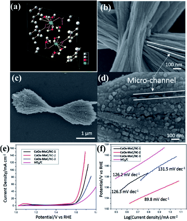 | ||
| Fig. 7 (a) Crystallographic structure for the Co-MOF. Reproduced with permission from ref. 159. (b) FESEM images of the hybrid Co–Mo-MOF. (c and d) Carbonized product obtained by the pyrolysis of Co–Mo-MOF (e) LSV curves of different electrocatalysts at 1600 rpm (f) comparative Tafel slopes for the different carbonized products. Reproduced with permission from ref. 148. Copyright 2017 Wiley. | ||
Li and group effectively utilized a nickel foam to grow MOF and proceeded on to carbonize it.149 First, they electrodeposited polyaniline (PAni) on nickel foam (NF) (NF@PAni). The layer of PAni promptly traps transition metal ions and upon exposure to H2dodc (2,5-dioxido-1,4-benzenedicarboxylic acid), the MOF-74-M [M2(dobdc)](M = Fe, Co, H2dodc = 2,5-dioxido-1,4-benzenedicarboxylic acid) grows on NF@PAni (NF@PAni@Co/Fe2O4-NRAs). This layered substrate was eventually pyrolyzed at 600 °C (Fig. 8). MOF-74-M was selected for the choice of metal (Fe, Co) and a high O/C ratio of the ligand. SEM images reveal the growth of MOF-74-Co/Fe nanorods (diameter ∼ 680 nm) array (NRA) on NF@PAni (Fig. 9(a)). The subsequent heat treatment under N2 atmosphere yielded Co/Fe2O4–C, denoted as NF@NC@Co/Fe2O4–C NRAs. Fig. 9(b) shows the SEM image of Co/Fe2O4–C NRAs with the inset showing a magnified nanorod. The TEM images of Co/Fe2O4–C ascertains the impregnation of metal NPs on a porous carbon matrix advantageous for catalytic activity (Fig. 9(c and d)).
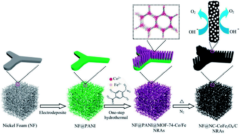 | ||
| Fig. 8 Schematic representation of one-step PANI-assisted synthesis of a bimetal–organic framework NRAs and its derived porous CoFe2O4/C NRAs. Reproduced with permission from ref. 149. Copyright 2017 Wiley. | ||
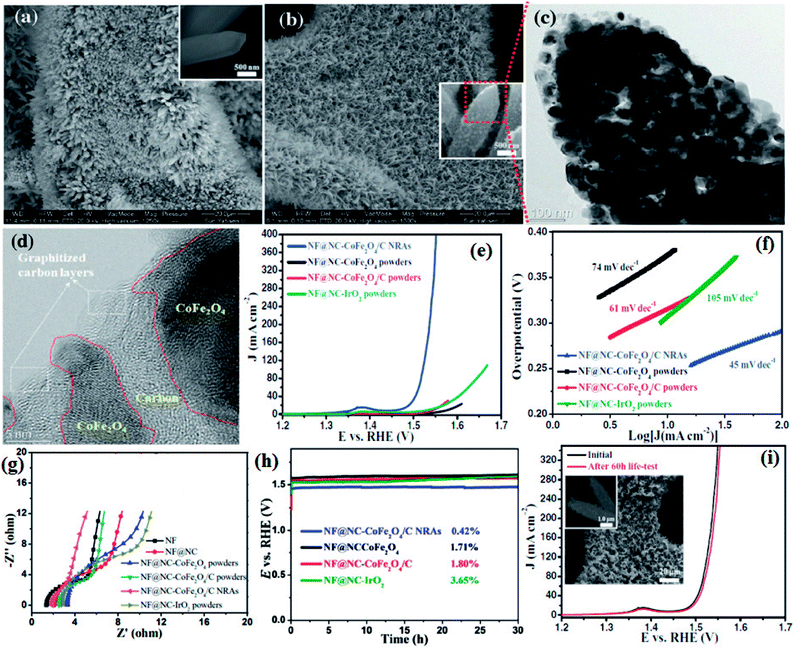 | ||
| Fig. 9 (a) SEM image of MOF-74-Co/Fe nanorod array (NRAs) (inset) one magnified MOF-74-Co/Fe nanorod (b) SEM image of CoFe2O4/C NRAs (inset) a magnified CoFe2O4/C nanorod. (c) TEM image of a CoFe2O4/C nanorod. (d) HRTEM image of CoFe2O4 nanoparticles encapsulated by carbon layers. (e) Polarization curves, (f) Tafel plots, (g) electrochemical impedance spectroscopy (EIS) recorded at open circuit potential and (h) chronopotentiometry curves of NF@NC-CoFe2O4/C NRAs, NF@NC-CoFe2O4 powders, NF@NC-CoFe2O4/C powders, and NF@NC-IrO2 powders in 1.0 M KOH solution. The chronopotentiometry was done at a current density of 10 mA cm−2. (i) LSVs of NF@NC-CoFe2O4/C NRAs before and after 60 h durability test at 100 mA cm−2 (inset shows the SEM images of the catalyst after durability test). Reproduced with permission from ref. 149. Copyright 2017 Wiley. | ||
Four types of electrodes were fabricated to show the advantages gained by growing NRAs on NF@PAni, which are as follows: (i) CoFe2O4 on NF@NC (NF@NC-CoFe2O4), (ii) CoFe2O4/C on NF@NC(NF@NC-CoFe2O4/C), (iii) commercial IrO2 on NF@NC (NF@NC-IrO2) on NF@NC, (iv) NF@NC@CoFe2O4/C NRAs. Upon performing the LSV, true to the conjecture of the authors, NF@NC@CoFe2O4/C NRAs showed the lowest onset potential (∼1.45 vs. RHE) (Fig. 9(e)) and Tafel slope was found to be ≈45 mV dec−1 (Fig. 9(f)), indicative of an extremely fast kinetics. The nanorod morphology of NF@NC@CoFe2O4/C NRAs plays an important role in accelerating the kinetics which in turn is the outcome of lower series resistance (Rs) and charge transfer resistance (RCT) (Fig. 9(g)). NF@NC@Co/Fe2O4–C NRAs also showed a stable chronopotentiometric response for 30 h (Fig. 9(h)). Polarization curves recorded before and after the durability test show very negligible change in the LSV profile, concluding the longevity of NF@NC-CoFe2O4/C NRAs (Fig. 9(i)).
In a recent work, a bimetallic ZIF-8 comprising both Ni and Zn has been carbonized between 700–1100 °C to obtain Ni induced tubular graphitic nanostructures (ZNDC). ZNDC-1100 shows excellent activity as a catalyst for OER, achieving benchmark 10 mA cm−2 current density at a low overpotential of 1.67 V, which is better than IrO2.163
Such attempts, although few, delineated the potential of MOFs in fabricating successful OER electrocatalysts from MOF derived carbon materials.
3.3 MOF derived electrocatalysts for hydrogen evolution reaction (HER)
Hydrogen Evolution Reaction (HER) is an important half-cell reaction in water splitting. Hydrogen being the most important next-generation clean fuel, efficient HER can lead to the sustainable generation of hydrogen that can be used in fuel cells. It is a classic example of a two-electron process and the reaction occurring is as follows:| 2H+ + 2e → H2 |
The benchmark catalyst in this case happens to be Pt. However in recent times MOF derived carbon materials have also been studied as electrocatalysts for this reaction.
The pyrolized derivatives of well-known MOFs, e.g., HKUST-1 (ref. 157) were initially explored for electrocatalysis without further modification (Fig. 10(a and b)). The octahedral shape of HKUST-1 (Fig. 10(c)) upon carbonization changed and adopted a distorted spherical “cauliflower-like” morphology (Fig. 10(d)), with particle sizes of ∼20 nm in its carbonized form regarded as Cu/NPC. EDS showed the presence of only C and Cu in Cu/NPC and the BET surface area was calculated to be ∼1025 m2 g−1. Upon being coated on GCE, Cu/NPC showed a decent activity as an electrocatalyst for HER in acidic medium producing a current density of −10.66 mA cm−2 at a potential of −1.0 V (vs. RHE). As expected, its activity was much better than that in the original HKUST-1. This has been attributed to the metallic Cu, CuO and Cu2O present in Cu/NPC, unlike the strong covalently bonded Cu in the HKUST framework. Moreover the high BET surface area as well H2 adsorption capacity provides an added advantage to Cu/NPC. Although the resistance to Faradaic process is greater in Cu/NPC than in HKUST-1 owing to the presence of Cu2O, the overall catalytic activity is much better in Cu/NPC.150
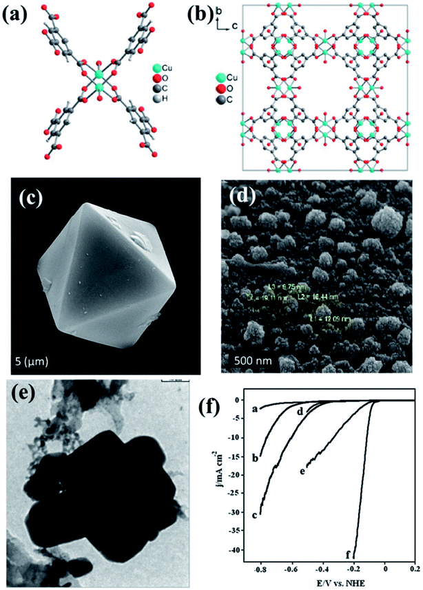 | ||
| Fig. 10 (a) Asymmetric unit of HKUST-1. (b) Packing of HKUST-1 in a direction. Reproduced with permission from ref. 157. Copyright 2012 Wiley. (c) Pyramidal HKUST nanoparticle before carbonization. (d) HKUST-1 after carbonization. (e) TEM image of Cu–Pd/NPCC/EC. Reproduced with permission from ref. 150. Copyright 2015, Elsevier. (f) LSV scan for HER on (a) bare GCE, (b) Cu/NPCC/HT/GCE, (c) Cu/NPCC/EC/GCE, (d) Pd/GCE, (e) Cu–Pd/NPCC/HT/GCE and (f) Cu–Pd/NPCC/EC/GCE in 0.5 M H2SO4 solution at 5 mV s−1. Reproduced with permission from ref. 151. Copyright 2018, Elsevier. | ||
In an extension to the afore-mentioned work, a novel catalyst containing Cu–Pd bimetallic nanoparticles supported on a nanoporous carbon was used for HER. Here, HKUST-1 was prepared in both hydrothermal and electrochemical methods. Thereby, they were carbonized and some of the Cu replaced by Pd using galvanic replacement, also known as trans-metalation. The composite material yielded from the electrochemically synthesized HKUST-1 (Cu–Pd/NPCC/EC (Fig. 10(e))) showed a much higher current density and lower overpotential than its hydrothermally synthesized counterpart (Fig. 10(f)). This has been attributed to the high specific surface area of Cu–Pd/NPCC/EC. Moreover, the electrochemical synthesis controls the oxidation state of Cu by the application of a proper potential and also enhances the Cu content.151
Xu et al., presented a very simple and effective method of preparing HER electrocatalysts active in both acid and alkaline medium by carbonizing ZIF-67 at 600 °C under N2 atmosphere to form Co/N–C.152 A vacuum phosphosulfurization process in the presence of P and S powders led to the formation of CoPS/N–C (Fig. 11(a)). Similar methods were used to prepare CoP2/N–C and CoS2/N–C nanocomposites for a comparative study. The ZIF-67 and all its derived nanocomposites were characterized by XRD, Raman spectroscopy, X-ray photoelectron spectroscopy which strongly attest the formation of CoPS/N–C with CoPS supported on N-doped carbon matrix. The polyhedral morphology of ZIF-67 was inherited by the CoPS/N–C with signs of structural collapse explained by the decrease in particle size caused due to the probable reconstruction of carbon framework during high temperature carbonization, phosphorization, sulfurization and phosphosulfurization processes (Fig. 11(b–d)). This shrinkage of carbon framework was also evident from the calculated BET surface areas (ZIF-67 = 1493 m2 g−1, Co/N–C = 317 m2 g−1 and CoPS/N–C = 69 m2 g−1). Co, P, S, C, N and O in CoPS/N–C were distributed uniformly on the polyhedrons as evident from the microscopic images and elemental mapping (Fig. 11(e)). The electrocatalytic activities of ZIF-67, Co/N–C, CoPS/N–C, CoP2/N–C and CoS2/N–C nanocomposites, towards HER were tested by casting them on a GCE and corresponding LSVs were tested in 0.5 M H2SO4 at a rotating speed of 2000 rpm. Pristine ZIF-67 was inactive whereas the nanocomposites showed a steep rise in the cathodic current, among which CoPS/N–C outperformed the CoP2/N–C, CoS2/N–C and Co/N–C. CoPS/N–C required an overpotential of −80 mV vs. RHE to achieve a current density of −10 mA cm−2 (Fig. 11(f)). The Tafel slope analysis proposed a two-electron transfer process following Volmer–Heyrovsky mechanism of bimolecular adsorption and hydrogen evolution (Fig. 11(g)). Also, the low value of the slope (69 mV dec−1) supports the efficient reaction kinetics. To find out the reason behind this excellent catalytic activity, double-layer capacitance (Cdl) and charge transfer resistance (RCT) were measured by CV and electrochemical impedance spectroscopy (EIS), respectively. The Cdl for CoPS/N–C was found to be the highest (21.55 mF cm−2) and RCT was found to be the lowest (4.8 Ω) among the other nanocomposites, signifying larger surface area, more accessible active sites and faster Faradaic response and hence faster kinetics (Fig. 11(h and i)). LSV recorded before and after 1000 cycles of CV at 50 mV s−1, showed a negligible shift in the overpotential. All the above experiments were also carried out in alkaline medium (1 M KOH) and CoPS/N–C was proven to be active towards HER with an overpotential of −128 mV, with Tafel slope of 78 mV dec−1.
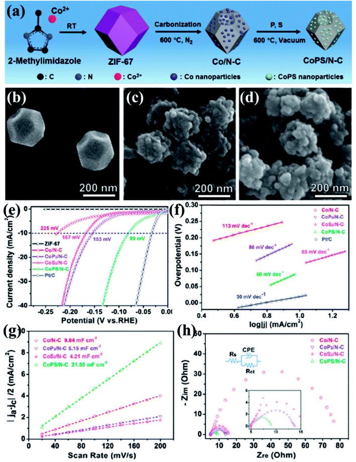 | ||
| Fig. 11 (a) Schematic representation of ZIF-67 synthesis and its subsequent conversion to Co/N–C and CoPS/N–C nanocomposites. SEM images of (b) ZIF-67, (c) Co/N–C and (d) CoPS/N–C. (e) Elemental mapping of CoPS/N–C showing evenly distributed Co, P, S, C, N and O. (f) Polarization curves for HER in comparison with Pt/C done in 0.5 M H2SO4. (g) Tafel plots for the corresponding polarization curves. (h) Nyquist plots (the inset shows the equivalent circuit used to simulate the Nyquist plots). Reproduced with permission from ref. 152. Copyright 2018 Royal Society of Chemistry. | ||
Wu and co-workers demonstrated a method to preserve the framework by in situ confinement of species inside the pore which prevents the agglomeration of the active sites in the carbon matrix.160 A Cu-based MOF [HKUST-1; Cu3(BTC)2(H2O)3] and a Mo-based POM (H3PMo12O40) were coprecipitated to form octahedral nanocrystallites of NENU-5 where POMs are confined inside the pores of HKUST-1. Upon carbonization of NENU-5 at 800 °C under N2 atmosphere, Mo reacts with carbonaceous ligands to form MoCx–Cu, whereas the presence of Cu2+ assists in the formation of MoCx by getting reduced to Cu. Finally, MoCx–Cu were converted to MoCx by etching the metallic Cu on treating with ferric chloride solution. A pictorial representation of the scheme is shown in Fig. 12(a). The Mo included structure shows a visible colour change, and also changes in the PXRD pattern (Fig. 12(b)).
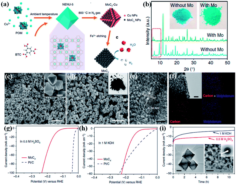 | ||
| Fig. 12 (a) Schematic representation of the synthetic procedure for porous MoCx nano-octahedrons (b) XRD patterns of NENU-5 (with Mo) and HKUST-1 (without Mo). (Inset) the corresponding sample photographs. (c) FESEM image of NENU-5. (Inset) magnified image, scale bar 500 nm. (d) Porous MoCx nano-octahedrons (inset) photograph. Scale bar, 2 μm. (e) HRTEM image (scale bar, 2 nm) (f) elemental mapping (red: carbon; blue: molybdenum; scale bar, 50 nm) of porous MoCx nano-octahedrons. Polarization curves at 2 mV s−1 in (g) 0.5 M H2SO4 and (h) in 1 M KOH. (i) Chronoamperometric curves under at an overpotential of 170 mV in 0.5 M H2SO4 and 180 mV in 1 M KOH (insets) TEM images and SAED pattern after 5000 potential sweeps in 0.5 M H2SO4. Scale bars: left inset 200 nm and right inset 20 nm. Reproduced from ref. 160 in accordance with Creative Commons Attribution 4.0 International License. | ||
The FESEM images of NENU-5 and MoCx show strikingly similar morphology (Fig. 12(c and d)). The high resolution transmission electron microscopy (HRTEM) image and the elemental mapping confirmed the uniform distribution of Mo nanoparticles with diameter of ∼5 nm embedded on the carbon matrix (Fig. 12(e and f)). The electrocatalytic activity of MoCx–Cu towards HER was studied in 0.5 M H2SO4 and 1 M KOH. An overpotential of 25 mV and 80 mV is required to initiate a cathodic current in acidic and alkaline media, respectively (Fig. 12(g and h)). The corresponding Tafel slopes of 53 mV dec−1 and 59 mV dec−1 signify fast kinetics. The electrocatalyst also showed excellent stability in both the media (Fig. 12(i)). This excellent HER activity is attributed to the Pt like electronic properties of MoC, brought about by high porosity and also by the availability of more active sites. The confinement strategy explored here negates agglomeration of active sites, keeping them exposed and catalytically active. The homogeneity of the morphology and the mesoporosity facilitates the charge and mass transport and hence providing faster reaction kinetics. The in situ confinement strategy for preparing electrocatalyst also opens up opportunities to design and synthesize high performing nanostructured transition metal carbides. These reports establish that indeed it is possible to synthesize highly efficient catalysts for HER from MOF derivatives.
4. Bifunctional electrocatalysts from MOF derived materials
While the superior activity of a material in a particular electrochemical reaction, e.g., OER, ORR or HER, is of utmost importance, practical electrolyzers require efficiency in multiple reactions for real-time use. While bifunctionality in OER and HER is essential for a material to have practical use in electrochemical water splitting, bifunctionality in ORR and OER is important in reversible fuel cells and metal–air batteries. In the attempt to explore MOF derived electrocatalysts, a few bifunctional catalysts were also developed.A commendable approach was reported by Qiao et al. who fabricated efficient bifunctional electrocatalysts by growing Co-naphthalenedicarboxylate {Co(C12H6O4)·(H2O)4} framework on a Cu foil by hydrothermal methods at moderate temperature (∼80 °C).153 As perceived from various microscopic techniques, the MOF grows on the Cu foil as arrays of nanowires with a diameter of ∼250 nm. These when subjected to carbonization under N2 atmosphere resulted in porous hybrid carbon nanowires with Co3O4 nanoparticles (Co3O4C-NA) (Fig. 13(a)). The microscopic images of the formed nanowires are shown in Fig. 13(b and c). Domains of crystalline Co3O4 demarcated by lattice fringes surrounded by amorphous phases were visible in HRTEM (Fig. 13(d and e)). Co3O4C-NA grown on Cu-foil can be directly used as working electrode for studying the electrocatalytic activity towards OER without any further processing. The authors systematically studied the catalytic contribution from Cu-foil, MOF and Co3O4C-NA. The polarization curve recorded in 0.1 M KOH shows both MOF and Co3O4C-NA to be active for OER (Fig. 13(f)). The corresponding Tafel plots are shown in Fig. 13(g). However, the pristine MOF showed a much lesser activity with the onset at ∼1.55 V vs. RHE, whereas Co3O4C-NA showed an onset at ∼1.47 V vs. RHE. Co3O4C-NA is not only active towards OER but are also active towards ORR and selectively produces water as the product, following a four electron pathway (Fig. 13(h)). This exceptional catalytic behavior arises due to a complex synergistic effect between Co3O4 and C which causes the active Co sites to be more electrophilic, thereby facilitating the adsorption and oxidation of OH− groups, showing enhanced OER activity in alkaline solutions. Also, the nanowire morphology of the catalysts assists in fast electron transfer. The nanowire morphology is also particularly advantageous in providing swift electrolyte penetration, whereas the mesopores assist the access of reactants in the electrolyte to the active sites. The nanowire morphology also helps in the faster release of the evolved O2. The most noteworthy advantage is growing the catalyst on conducting supports which ensures better adhesion between nanowire arrays and substrates, greatly enhancing the electron transport, structural stability, without the use of binders and conductive fillers. Owing to this fast kinetics, Co3O4C-NA shows a Tafel slope much smaller than benchmark IrO2/C for OER.
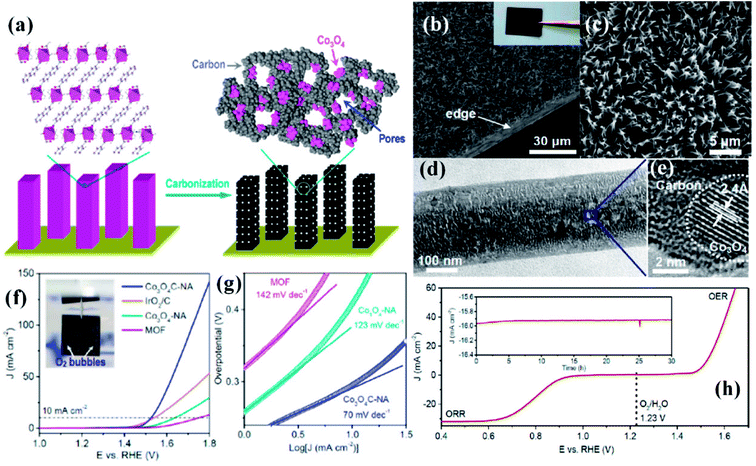 | ||
| Fig. 13 (a) Preparation of porous hybrid carbon nanowires with Co3O4 nanoparticles (Co3O4C-NA); (b and c) SEM images of Co3O4C-NA in different magnifications (inset) sample photograph. (d) TEM image of Co3O4C-NA. (e) HRTEM image of Co3O4C-NA. (f) Polarization curves and (g) Tafel plots of Co3O4C-NA (h) polarization curve measured in O-saturated 0.1 M KOH solution (scan rate 0.5 mV s−1) for Co3O4C-NA grown on Cu foil (directly used as the working electrode) in the whole region of OER and ORR. Inset: chronoamperometric response of Co3O4C-NA at a constant potential of 0.78 V (E1/2), with methanol addition after 25 h. Reproduced with permission from ref. 153. Copyright 2014, American Chemical Society. | ||
Recently, we have reported synthesis and detailed characterization of an efficient and stable bi-functional electrocatalyst derived from a 3D metal–organic framework {[Co(bpe)2(N(CN)2)]N(CN)2·5H2O} (Co-MOF), (bpe = 1,2-bis(4-pyridyl)ethane and N(CN)2− = dicyanamide) (Fig. 14(a)).121 The 3D framework of Co-MOF is composed of bridging bpe linkers which forms a 2D [Co(bpe)2]2+ layer and this is further pillared by N(CN)2− anions (Fig. 14(b)). The presence of large no of CoII–N6 moieties in the structure could lead to the formation of electrochemical active M–N–C sites. This Co-MOF was chosen as a carbonization template due to two reasons, (a) the presence of electroactive CoII metal ion, which can also catalyze organic precursors to form carbon nanotube under pyrolyzing condition at H2 atmosphere; (b) secondly, the presence of N(CN)2, a well known chemical precursor for g-C3N4 that can lead to the formation of N-doped graphitic nanostructures. The two different catalysts were prepared by pyrolyzing Co-MOF at different conditions. Pyrolyzing at 800 °C under Ar atmosphere and at 800 °C under H2/Ar atmosphere resulted in Co-NCNT-Ar and Co-NCNT-H2 (NCNT = nitrogen doped carbon nanotube), respectively. Furthermore, Co-NCNT-H2 was calcined in air at 250 °C to obtain Co3O4@Co/NCNT composite material. Both the carbonized materials were characterized by PXRD, Raman spectroscopy, XPS, FESEM and TEM techniques. XRD pattern of Co-NCNT-Ar suggests the presence of metallic cubic Co phase on the regular graphitic carbon (Fig. 14(c)). Raman spectra showed D and G bands and their ratio suggests a high degree of graphitization in Co-NCNT-Ar and Co3O4@Co/NCNT (Fig. 14(d)). Raman spectra of Co3O4@Co/NCNT also showed the bands characteristics of typical Co3O4 spinel phase. XPS survey spectra for both the composite materials showed the presence of Co, C, N and O. Along with metallic Co, the presence of spinel like Co–N4, Co(Co)4 and Co–N–C was also realized from XPS spectra (Fig. 14(e)). The detailed morphological feature of the carbonized product was realized from FESEM and TEM imaging. The microscopic study showed that in Co/NCNT-Ar, the Co nanoparticles are embedded in a continuous self-coiled N-doped carbon nanotube matrix, where the average diameter of Co nanoparticles and nanotubes are in the range of 50–110 nm and 50–200 nm, respectively (Fig. 14(f)). HRTEM showed lattice fringes with spacing of about 0.209 nm which corresponds to the {111} of the cubic metal structure. Pyrolysis under H2 atmosphere also led to the formation of self-coiled dense N-doped carbon nanotube where metallic Co nanoparticles (40–50 nm) are embedded. After calcination in air, TEM images revealed the formation of core–shell nanoparticles Co3O4@Co encapsulated in a CNT matrix. The length and diameter of the nanotubes are in the range of 100–200 nm and 10–20 nm, respectively. The lattice fringe of the outer shell of Co3O4@Co nanoparticles is 0.46 nm which is characteristic cubic {111} structure of Co3O4 and higher than that of Co (0.209 nm) (Fig. 14(g)). The permanent porosity was measured by the N2 adsorption study at 77 K to elucidate the textural parameters (Fig. 14(h)). Both Co-NCNT-Ar and Co3O4@Co-NCNT showed typical type IV isotherm with BET surface area of 58 and 118 m2 g−1, respectively. Both the samples showed wide pore size distribution (2–30 nm). Electrochemical ORR and OER activities for Co-NCNT-Ar and Co@Co3O4-NCNT were tested. Cyclic voltammetry (CV) in O2 saturated 0.1 M KOH solution for Co-NCNT-Ar and Co3O4@Co/NCNT was measured and showed good catalytic activity towards ORR at ≈0.87 and 0.9 V (vs. RHE), respectively(Fig. 15(a and b)). LSV of Co3O4@Co/NCNT using a RDE electrode at different rotation speeds revealed a remarkable catalytic performance for ORR affording a current density of −1 mA cm−2 at low overpotential of 0.88 V (onset 0.93 V vs. RHE), and this value is 0.83 for Co-NCNT-Ar (onset at 0.9 V vs. RHE). Co3O4@Co/NCNT reveals a very close ORR activity to that of commercial Pt/C (Fig. 15(c and d)). Koutecky–Levich (K–L) plots suggested first order reaction kinetics with respect to the dissolved O2 concentration and number of electrons transferred (n) per O2 molecule during the ORR to be in the range of 3.92 to 3.96 suggesting the reduction of O2 predominantly through the 4 electron transfer pathway. Interestingly Co-NCNT-Ar showed 2 electron transfer pathway. RRDE measurement further confirmed it based on the percentage of H2O2 production (Fig. 15(e)). Co-NCNT-Ar showed about 54% H2O2 production in the entire potential range (0.8 to 0.3 V vs. RHE) and Co3O4@Co-NCNT showed only 1% H2O2 production. The relatively lower Tafel slope of 61 mV dec−1 for Co3O4@Co-NCNT compared to Co-NCNT-Ar (74 mV dec−1) indicating faster reaction kinetics for the former (Fig. 15(f)).
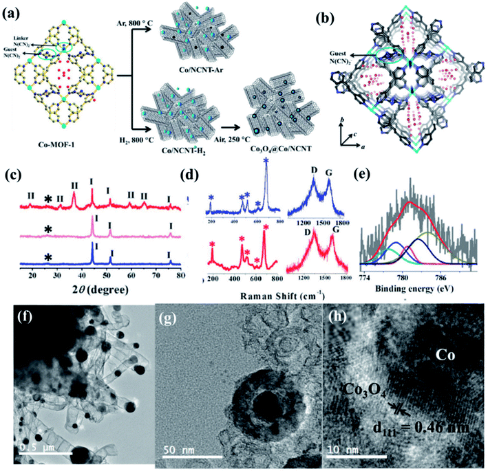 | ||
| Fig. 14 (a) Schematic representation of the carbonization of Co MOF. (b) N-rich 3D interpenetrated framework of Co MOF [cyan = Co, blue: N, grey: C, red: oxygen]; the small circle represents the guest N(CN)2− and the red sticks represent free guest N(CN)2− anions, red balls represent guest water molecules (c) PXRD pattern of Co/NCNT-Ar (blue), Co/NCNT-H2 (pink), and Co3O4@Co/NCNT (red); *, I, II denote the graphitic (002) peak, Co peaks, and Co3O4 peaks, respectively; (d) Raman spectra of Co/NCNT-Ar (blue) and Co3O4@Co/NCNT (red) showing Co3O4 phase, along with the characteristic D and G bands. (e) Co2p spectrum from XPS. (f) TEM image of Co/NCNT-Ar. (g) Co3O4@Co core–shell nanoparticle embedded in a NCNT matrix in Co3O4@Co/NCNT; (h) HRTEM image of a single Co3O4@Co nanoparticle showing lattice fringes. Reproduced with permission from ref. 121. Copyright 2017 Wiley. | ||
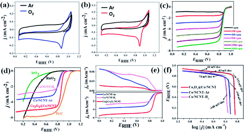 | ||
| Fig. 15 CVs for (a) Co/NCNT-Ar and (b) Co3O4@Co/NCNT recorded at a scan rate of 5 mV s−1 in O2-saturated and Ar-saturated 0.1 M KOH solution; (c) LSV curves recorded at various rotation speeds for Co3O4@Co/NCNT; (d) iR-corrected linear sweep voltammograms of different electrocatalysts collected at 1600 rpm in O2-saturated 0.1 M KOH solution; (e) RRDE polarization curves for the ORR at 1600 rpm for Co/NCNT-H2, Co/NCNT-Ar and Co3O4@Co/NCNT; (f) ORR Tafel slopes of Co/NCNT-Ar, Co/NCNT-H2 and Co3O4@Co/NCNT. Reproduced with permission from ref. 121. Copyright 2017 Wiley. | ||
OER activity is also observed to be superior for Co3O4@Co-NCNT compared to Co-NCNT-Ar as the former attained a current density of 10 mA cm−2 at a potential of 1.61 V vs. RHE, whereas later reached the same current density at 1.76 V at 1600 rpm (Fig. 16(a)). In a similar condition RuO2 and IrO2 exhibited 1.64 and 1.69 V (vs. RHE), respectively suggesting Co3O4@Co-NCNT surpasses the benchmark catalysts (Fig. 16(a)). The Tafel slopes for the OER are 58.7 mV per decade and 80 mV per decade for Co3O4@Co-NCNT and Co-NCNT-Ar, respectively, indicating reaction kinetics substantially faster for the former (Fig. 16(b)). Interestingly the overpotential difference between ORR (at current density of −1 mA cm−2) and OER (at current density of 10 mA cm−2) is about 0.73 V, indicating high efficiency of Co3O4@Co-NCNT as ORR and OER bifunctional catalyst (Fig. 16(c)). This is an important parameter for evaluating the bifunctionality for a reversible oxygen electrode. This value is lowest among all the state of art catalysts. Furthermore chronoamperometric stability measurement suggested no significant decline in the current in the course of 30–40 h of continuous polarization, indicating high stability of both the catalyst (Fig. 16(d)). The high catalytic activity for Co3O4@Co-NCNT was attributed to the high surface area, presence of highly active sites and the synergistic interaction between conductive metallic Co cores and the semi conductive Co3O4 shell. All these parameters facilitate an easy mass diffusion and faster charge transfer in the NCNT network.
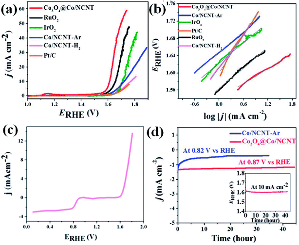 | ||
| Fig. 16 (a) iR-corrected linear sweep voltammograms of different electrocatalysts at 1600 rpm; (b) corresponding OER Tafel plots; (c) iR-corrected LSV recorded at 1600 rpm showing bifunctional activity of Co3O4@Co/NCNT; (d) chronoamperometric stability of Co/NCNT-Ar and Co3O4@Co/NCNT; inset shows chronopotentiometric stability of Co3O4@Co/NCNT at 10 mA cm@2 at 1600 rpm. Reproduced with permission from ref. 121. Copyright 2017 Wiley. | ||
In a similar work by Muhler et al., bifunctionality in OER and ORR was demonstrated based on core–shell Co@Co3O4 nanoparticles embedded in CNT grafted N-doped polyhedral obtained by the pyrolysis of ZIF-67.120 In this case, in the carbonized form, polyhedrons containing Co nanoparticles are wrapped in few layers of CNT. The Co@Co3O4 particles are wrapped in graphene like highly graphitized carbon sheets. The width of the Co3O4 shell can be controlled by the time of calcination of the sample in O2 environment and two such samples were prepared with calcination times of 2 and 6 h respectively (Co@Co3O4/NC-1 and Co@Co3O4/NC-2). While Co@Co3O4/NC-1 shows a better activity in ORR, Co@Co3O4/NC-2 has a better performance in OER, with a current density of −10 mA cm−2 achieved merely at 1.64 V. However, upon considering bifunctionality, it is observed that overall Co@Co3O4/NC-1 is a more efficient electrocatalyst, with comparable activity in ORR with Pt/C and in OER with IrO2 and Pt/C. As suggested in this work, the small overvoltage in bifunctionality between ORR and OER translates in to energy saving of at least 150 mV and 100 mV for Co@Co3O4/NC-1 and Co@Co3O4/NC-2, respectively.120
An attempt towards fabricating bifunctional catalysts was also made by carbonizing ZIF-67 at various temperatures from 600–2000 °C under Ar atmosphere.154 While at lower temperature, the morphology of the ZIF-67 nanoparticles is maintained in the carbonized form, at higher temperatures, carbon nanotubes are observed at the surface, whose formation has been catalyzed by the presence of cobalt. At 1200 °C, cobalt form large aggregates, wrapped by sheets of graphitic carbon. Beyond 1600 °C, the morphology was primarily that of hollow carbon onions. The sample that had been pyrolyzed at 800 °C, i.e., Co@C-800, shows an excellent ORR activity with an onset potential of 0.92 V (vs. RHE), along with a 4 electron transfer pathway and excellent stability. This stability can be attributed to the protection of the Co nanoparticles by the layers of carbon matrix. Moreover, the excellent bifunctionality of Co@C-800 is established upon investigating its role in OER. It showed an onset potential of 1.43 V and a potential of merely 1.61 V is required to achieve a current density of 10 mA cm−2. In this work, the direct effect of the carbonization temperature on the electrochemical activity has been shown. In case of Co@C-800, Co and N dopants could induce a positive charge on the adjacent carbon atoms, thereby assisting in the adsorption of OH− and electron transfer.154
MOF derived dual catalysts have been also attempted for HER and OER, thereby showing activity as a catalyst for overall water splitting. A recent work involves the pyrolysis of the zeolitic imidazolate framework ZIF-8 (Zn(MIM)2) to generate a N containing porous carbon. Using cathodic polarization treatment (CPT) up to 8 h, the N and O containing surface groups are modulated without compromising its large surface area or pore size distribution (Fig. 17(a)). A sample having undergone 6 h CPT shows an excellent HER activity in 0.5 M H2SO4 electrolyte with an overpotential of 155 mV, a Tafel slope of 54.7 mV dec−1 and an exchange current density of 0.063 mA cm−2 (Fig. 17(b)). CPT of 4 h results in excellent OER activity in 0.1 M KOH electrolyte with an overpotential of 476 mV and a Tafel slope of 78.5 mV dec−1(Fig. 17(c)). These carbon electrolyzers successfully run a two-electrode water splitting reaction at a current density of 10 mA cm−2 over 8 h under a potential of 1.82 V with a Faradaic efficiency of ∼99% in 0.1 M KOH (Fig. 17(d)).155 By careful investigation, it has been found that in this case the presence of oxidized N and carboxylic O sites on the surface is specifically effective in improving the HER kinetics as these are the active sites. Although in this case, it has been proven that surface area and pore size are not determining factors, larger ECSA definitely ensures better activity. Moreover, investigation of Raman spectra also showed that higher carbonization time inflicts higher number of defects and severe structural damage to the graphitic carbon matrix, thereby lowering activity.155
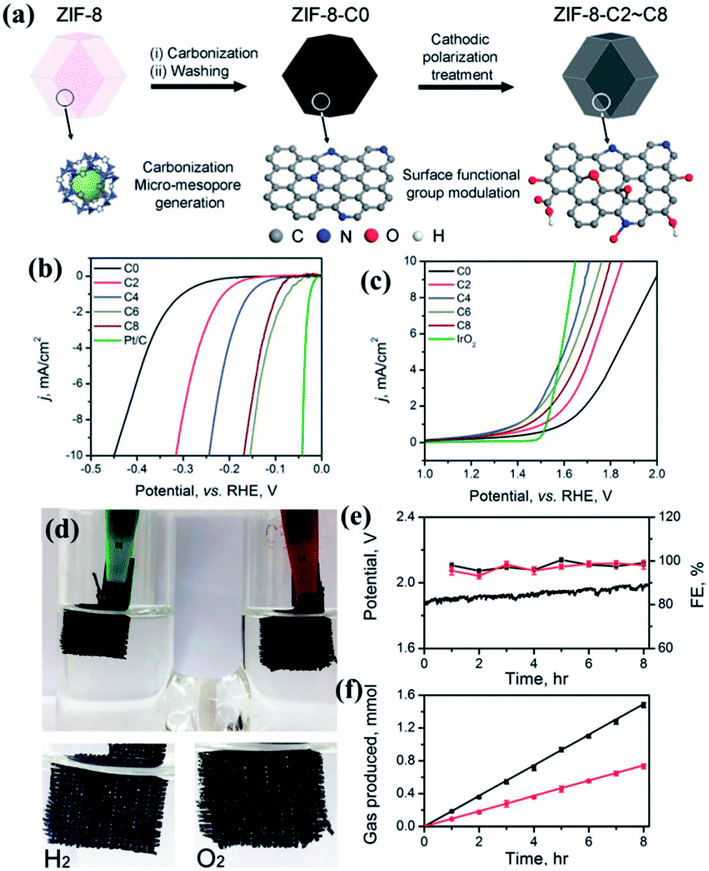 | ||
| Fig. 17 (a) Schematic representation of the formation of carbon electrocatalysts from ZIF-8. (b) HER LSV polarization and (c) OER LSVs for different carbon samples undergoing CPT for different time durations. (d) Photograph of the electrolyzer performing total water splitting performance of the ZIF-8-C4 at anode and ZIF-8-C6 at cathode in 0.1 M KOH. (e) Water splitting under a current density of 10 mA cm−2 for 8 h and the Faradaic efficiency for HER and OER, respectively. (f) The amount of H2 and O2 released from the electrolyzer was quantified by GC. Reproduced with permission from ref. 155. Copyright 2018 Royal Society of Chemistry. | ||
ZIF-67 because of its large cobalt content is an automatic choice for carbonization. Porous Co–P/NC nanopolyhedrons comprising CoPx nanoparticles embedded in N containing C matrix was prepared by the direct carbonization of ZIF-67, followed by phosphidation. This shows excellent performance in both HER and OER in 0.1 M KOH, with low overpotentials and high current density, showing an activity even better than Pt or IrO2. This superior activity has been attributed to their high specific surface area along with interconnected mesoporosity, good conductivity and the dual effect of doped CoPx and the N-dopants.156 In a similar approach, Sun et al. also grew ZIF-67 on a carbon cloth, followed by subsequent carbonization and phosphidation to yield a Co, N and P containing carbon matrix named Co–P/NC/CC. This material shows an excellent HER activity in 1.0 M KOH with an onset potential of −0.1 V vs. RHE. It also showed an onset potential of 1.5 V vs. RHE for OER in 1.0 M KOH and achieves a current density of 10 mA cm−2 at an overpotential of merely 330 mV. The superior activity of Co–P/NC/CC is not only because of a larger ECSA, but also because the large content of cobalt phosphides. A two-electrode electrolyzer fabricated using this system at cathode and anode in 1.0 M KOH for overall water-splitting, where it shows an onset of 1.7 V and achieves current densities of 10 and 100 mA cm−2 at cell voltages of 1.77 and 1.93 V, respectively.162
Bifunctionality achieved in mesoporous nitrogen doped graphene (MNG) obtained from ZIF-67 has also been exploited in a multi-functional electrode for Zn–air battery and water splitting device. Here, ZIF-67 has been first grown as fibers on the surface of NaCl crystals and post carbonization, NaCl has been washed away with acid, to yield MNG, which has a much higher ECSA than the porous carbon derived from typical polyhedral ZIF-67. MNG–CoFe with encapsulated CoFe alloy nanoparticles showed excellent ORR, OER and HER performances, comparable to benchmark noble metal catalysts. MNG–CoFe when assembled as a multifunctional electrode in the rechargeable Zn–air battery showed high power density and cycling durability. Moreover in a water-splitting device, it showed very low overpotential, outperforming the benchmark catalysts.164
Although in most cases, Co and Ni nanoparticles have been exploited for catalysis, Cu has also been used for bifunctional catalysis. For this purpose, a MOF Cu-NPMOF (containing Cu2+, pyrazine and HEDP = 1-hydroxyethylidene-1,1-diphosphonic acid) has been used where Cu2+ is connected by P containing 1-hydroxyethylidene-1,1-diphosphonic acid (HEDP) and N containing pyrazine. Upon carbonization, Cu3P nanoparticles coated by N and P-doped carbon shell are formed, which extends to a hierarchical porous carbon matrix (Cu3P@NPPC). Cu3P@NPPC is an excellent catalyst for both HER and OER.165
Thus several unique approaches have been adopted to synthesize MOF-derived porous carbon with distinct morphologies and composition showing superior activity. While we have mentioned some over here, many more attempts have been undertaken in this global endeavor of finding cheap alternatives of noble metals for renewable energy technology. The various MOF-derived electrocatalysts that have been discussed in this review has been concisely summarized in Table 1 with their properties and activities.
| Type of electro-catalyst | Material | Derived from MOF | Morphology | Heteroatoms/transition metals present | Activity | Ref. no. |
|---|---|---|---|---|---|---|
| ORR catalyst | P–CN–Co-20 | BMZIF (bi-metallic ZIF-67) | Co nanoparticles on graphitized carbon | N, P, Co | Onset: −0.04 V vs. Ag/AgCl | 141 |
| NCD-1 | {[Mg3(ndc)2.5(HCO2)2(H2O)]·[NH2Me2]·2H2O·DMF} | Spherical dots | N | 1 mA cm−2 at 0.36 V vs. RHE | 129 | |
| Co@CN | Co nanoparticles on carbon nitride | Co, N | 1 mA cm−2 at 0.8 V vs. RHE | |||
| NSMC-900 | SCUT-12 [Zn2(TDC)2(DABCO)]·4DMF | Porous planar | N, S | Onset: 0.98 V vs. RHE; comparable to 40 wt% Pt/C | 144 | |
| MDC300 | ZIF-67 | Polyhedral | Co, N | Onset: 0.86 V vs. RHE | 145 | |
| P-Z8-Te-1000 | ZIF-8 grown on Te nanowires | Fibrous | N, P | Onset: −0.22 V vs. Ag/AgCl; better than 20 wt% Pt/C | 146 | |
| BHPC-950 | ZIF-8 supported on silica matrix | Interconnected macroporous carbon texture | N | Onset: 0.93 V vs. RHE; Zn–air & Li–S batteries | 147 | |
| OER catalyst | CoOx–MoC/NC-1 | Co–Mo-MOF | 3D nanowire assembly | Co, Mo, N | Onset: 1.52 V vs. RHE; Tafel slope 89.8 mV dec−1. | 148 |
| NF@NC@Co/Fe2O4–C NRAs | MOF-74-M (M = Fe, Co) | Nanorod array | Co, Fe, N | Onset: 1.45 V vs. RHE; Tafel slope 45 mV dec−1. | 149 | |
| ZNDC-1100 | Bimetallic ZIF-8 (Ni, Zn) | Tubular graphitic nanostructure | Ni, N | 10 mA cm−2 at 1.67 V | 163 | |
| HER catalyst | Cu/NPC | HKUST-1 | “Cauliflower-like” morphology | Cu | 10.66 mA cm−2 at −1.0 V | 157 |
| Cu–Pd/NPCC/EC | Electrochemically prepared HKUST-1 | Metal NPs on porous network | Cu, Pd | Onset: −0.13 V vs. RHE | 151 | |
| CoPS/N–C | ZIF-67 | Polyhedra with CoPS NPs | Co, P, S, N | Overpotential: 80 mV vs. RHE; Tafel slope 68 mV dec−1. | 152 | |
| MoCx | NENU-5 | Nano-octahedrons | Mo | Overpotential: 80 mV vs. RHE in alkaline and 25 mV in acidic media | 160 | |
| Bifunctional electrocatalyst | Co3O4C-NA | {Co(C12H6O4)·(H2O)4} framework grown on Cu foil | Hybrid carbon nanowires | Co | OER onset: 1.55 V vs. RHE. ORR half-wave potential: 0.78 V vs. RHE. Tafel slope: 89 mV dec−1. | 153 |
| Co3O4@Co/NCNT | Co-MOF | N-doped carbon nanotubes with metal NPs | Co, N | OER onset: 1.61 V vs. RHE. ORR onset: 0.9 V vs. RHE. Comparable to RuO2 and IrO2. | 121 | |
| Co–P/NC | ZIF-8 | Nanopolyhedrons | Co, P, N | HER: −154 mV overpotential to reach 10 mA cm−2. OER onset: 1.5 V vs. RHE. Water-splitting | 156 | |
| MNG–CoFe | ZIF-67 fibres | Fibrous | Co, Fe, N | ORR, OER, HER better than benchmark catalysts. Zn–air battery and water-splitting device | 164 |
5. Conclusions and future perspectives
This review documents some of the recent research conducted to develop low cost, noble metal-free electrocatalysts derived from MOF. MOFs act as perfect template for generating such carbon materials owing to their innate porosity, stable structure, high carbon content and ease of heteroatom doping. However, the synthesis of efficient carbon based materials requires careful selection of the MOF precursor and the annealing temperature, along with morphology and size control. Till date, quite a few materials have been generated using MOF which are excellent noble metal-free electrocatalysts and have helped in taking a big stride towards cheap alternative catalysts. New and innovative approaches were brought into light which could be utilized to design a plethora of such functional materials. The methodically developed MOF derived materials having favourable electronic structure based on heteroatom doped carbon matrix along with metal or metal compound NPs, can show excellent electrochemical activity. Moreover, suitable morphologies and pore structure that facilitate electron and mass transport are instrumental in developing highly potent electrocatalyst for OER, ORR and HER.Highly potent MOF-derived carbon-based electrocatalysts can be synthesized by carefully considering the following points:
(1) Careful selection of the MOF is supremely important since ligand composition provides the carbon template with heteroatoms like N, P and S. Similarly, redox-active metal ion from the MOF provides the metal or metal oxide nanoparticles.
(2) Morphology, size and shape of the as synthesized MOF is also crucial as it determines the morphology and corresponding textural parameter of the resultant carbonaceous material.
(3) Pyrolysis temperature and condition are also important parameters which plays a crucial role in determining the morphology and composition of the resultant carbon nanocomposite.
Targeted design and synthesis of tailored MOFs has the potential to develop next-generation materials with superior activity for the commercialization of energy devices like fuel cells and metal–air batteries. Until now, MOF derived functional materials have been exploited as bifunctional catalysts but trifunctional catalysts which can catalyze all the three half reactions-OER, ORR and HER efficiently are yet to be developed from such materials. Such trifunctional materials are ideal for practical use in regenerative fuel cells, electrolyzer, overall water-splitting and metal–air batteries. This missing link can be filled by careful considerations of the design strategies discussed in this review. Thus, this review not only paves way for better understanding of the foundation of designing materials but also throws a challenge to develop an all-in-one trifunctional catalyst from MOF precursor. Another obstacle that needs to be overcome is the poor conductivity of pristine MOFs in order to develop electrochemically active MOFs. Absence of studies that provide a deep insight to the mechanism of the electrocatalytic activities of these materials is also another hurdle in their otherwise steady advancement and this void can be filled by suitable proper theoretical approaches. Additionally, merely the development of new materials is not adequate to fight the global energy demand, sincere efforts to support their application in clean energy technology are also necessary, which would require more rigorous and meticulous performance and stability test. Thus, the challenge is still open to develop electrocatalysts with supreme efficiency and stability along with proper mechanistic insights for successful commercialization of sustainable clean energy techniques.
Conflicts of interest
There are no conflicts to declare.Acknowledgements
S. B. is grateful to INSPIRE Fellowship, Department of Science and Technology, Govt. of India, for fellowship. T. K. M. is grateful to the Department of Science and Technology (DST, Project No. MR-2015/001019 and Project No. TRC-DST/C.14.10/16-2724, JNCASR), Govt. of India and JNCASR for financial support.References
- N. Apergis and J. E. Payne, Energy Econ., 2012, 34, 733 CrossRef.
- M. Hoel and S. Kverndokk, Resour. Energy Econ., 1996, 18, 115 CrossRef.
- M. Höök and X. Tang, Energy Policy, 2013, 52, 797 CrossRef.
- S. Shafiee and E. Topal, Energy Policy, 2009, 37, 181 CrossRef.
- M. Liserre, T. Sauter and J. Hung, IEEE Ind. Electron. Mag., 2010, 4, 18 Search PubMed.
- I. Dincer, Renewable Sustainable Energy Rev., 2000, 4, 157 CrossRef.
- R. Baños, F. Manzano-Agugliaro, F. G. Montoya, C. Gil, A. Alcayde and J. Gómez, Renewable Sustainable Energy Rev., 2011, 15, 1753 CrossRef.
- H. Lund, Energy, 2007, 32, 912 CrossRef.
- A. Hepbasli, Renewable Sustainable Energy Rev., 2008, 12, 593 CrossRef.
- C. Zhong, Y. Deng, W. Hu, J. Qiao, L. Zhang and J. Zhang, Chem. Soc. Rev., 2015, 44, 7484 RSC.
- C. Du, J. Yeh and N. Pan, Nanotechnology, 2005, 16, 350 CrossRef.
- G. Wang, L. Zhang and J. Zhang, Chem. Soc. Rev., 2012, 41, 797 RSC.
- M. Zhi, C. Xiang, J. Li, M. Li and N. Wu, Nanoscale, 2013, 5, 72 RSC.
- X. Su, Q. Wu, J. Li, X. Xiao, A. Lott, W. Lu, B. W. Sheldon and J. Wu, Adv. Energy Mater., 2014, 4, 1300882 CrossRef.
- L. Ji, Z. Lin, M. Alcoutlabi and X. Zhang, Energy Environ. Sci., 2011, 4, 2682 RSC.
- V. Etacheri, R. Marom, R. Elazari, G. Salitra and D. Aurbach, Energy Environ. Sci., 2011, 4, 3243 RSC.
- L. Carrette, K. A. Friedrich and U. Stimming, Fuel Cells, 2001, 1, 5 CrossRef.
- S. P. S. Badwal and K. Foger, Ceram. Int., 1996, 22, 257 CrossRef.
- N. W. DeLuca and Y. A. Elabd, J. Polym. Sci., Part B: Polym. Phys., 2006, 44, 2201 CrossRef.
- K. G. Gallagher, S. Goebel, T. Greszler, M. Mathias, W. Oelerich, D. Eroglu and V. Srinivasan, Energy Environ. Sci., 2014, 7, 1555 RSC.
- M. Park, H. Sun, H. Lee, J. Lee and J. Cho, Adv. Energy Mater., 2012, 2, 780 CrossRef.
- F. Cheng and J. Chen, Chem. Soc. Rev., 2012, 41, 2172 RSC.
- J. Suntivich, H. A. Gasteiger, N. Yabuuchi, H. Nakanishi, J. B. Goodenough and Y. Shao-Horn, Nat. Chem., 2011, 3, 546 CrossRef PubMed.
- Z.-L. Wang, D. Xu, J.-J. Xu and X.-B. Zhang, Chem. Soc. Rev., 2014, 43, 7746 RSC.
- Y. Li and H. Dai, Chem. Soc. Rev., 2014, 43, 5257 RSC.
- D. R. Dekel, M. Amar, S. Willdorf, M. Kosa, S. Dhara and C. E. Diesendruck, Chem. Mater., 2017, 29, 4425 CrossRef.
- L. Ma, S. Chen, Z. Pei, Y. Huang, G. Liang, F. Mo, Q. Yang, J. Su, Y. Gao, J. A. Zapien and C. Zhi, ACS Nano, 2018, 12, 1949 CrossRef PubMed.
- L. Li, J. Yang, H. Yang, L. Zhang, J. Shao, W. Huang, B. Liu and X. Dong, ACS Appl. Energy Mater., 2018, 1, 963 CrossRef.
- T. An, X. Ge, N. N. Tham, A. Sumboja, Z. Liu and Y. Zong, ACS Sustainable Chem. Eng., 2018, 6, 7743 CrossRef.
- Q. Liu, Z. Chang, Z. Li and X. Zhang, Small Methods, 2018, 2, 1700231 CrossRef.
- J. Pan, Y. Y. Xu, H. Yang, Z. Dong, H. Liu and B. Y. Xia, Adv. Sci., 2018, 5, 1700691 CrossRef PubMed.
- L. Carrette, K. A. Friedrich and U. Stimming, Fuel Cells, 2001, 1, 5 CrossRef.
- M. A. Laguna-Bercero, R. Campana, A. Larrea, J. A. Kilner and V. M. Orera, Fuel Cells, 2011, 11, 116 CrossRef.
- J. Pettersson, B. Ramsey and D. Harrison, J. Power Sources, 2006, 157, 28 CrossRef.
- M. Lefèvre, E. Proietti, F. Jaouen and J.-P. Dodelet, Science, 2009, 324, 71 CrossRef PubMed.
- X. Zhou, J. Qiao, L. Yang and J. Zhang, Adv. Energy Mater., 2014, 4, 1301523 CrossRef.
- S. S. Dihrab, K. Sopian, M. A. Alghoul and M. Y. Sulaiman, Renewable Sustainable Energy Rev., 2009, 13, 1663 CrossRef.
- R. J. Gorte, S. Park, J. M. Vohs and C. Wang, Adv. Mater., 2000, 12, 1465 CrossRef.
- L. Li and A. Manthiram, Adv. Energy Mater., 2016, 6, 1502054 CrossRef.
- J. Fu, F. M. Hassan, J. Li, D. U. Lee, A. R. Ghannoum, G. Lui, M. A. Hoque and Z. Chen, Adv. Mater., 2016, 28, 6421 CrossRef PubMed.
- J. Zhang, J. Fu, X. Song, G. Jiang, H. Zarrin, P. Xu, K. Li, A. Yu and Z. Chen, Adv. Energy Mater., 2016, 6, 1600476 CrossRef.
- J.-S. Lee, S. Tai Kim, R. Cao, N.-S. Choi, M. Liu, K. T. Lee and J. Cho, Adv. Energy Mater., 2011, 1, 34 CrossRef.
- D. U. Lee, H. W. Park, M. G. Park, V. Ismayilov and Z. Chen, ACS Appl. Mater. Interfaces, 2015, 7, 902 CrossRef PubMed.
- S. H. Ahn and A. Manthiram, Small, 2017, 13, 1702068 CrossRef PubMed.
- V. M. Dhavale and S. Kurungot, ACS Catal., 2015, 5, 1445 CrossRef.
- E. Yoo, T. Okata, T. Akita, M. Kohyama, J. Nakamura and I. Honma, Nano Lett., 2009, 9, 2255 CrossRef PubMed.
- N. M. Marković, T. J. Schmidt, V. Stamenković and P. N. Ross, Fuel Cells, 2001, 1, 105 CrossRef.
- Z. Peng and H. Yang, J. Am. Chem. Soc., 2009, 131, 7542 CrossRef PubMed.
- V. R. Stamenkovic, B. S. Mun, K. J. J. Mayrhofer, P. N. Ross and N. M. Markovic, J.Am. Chem. Soc., 2006, 128, 8813 CrossRef PubMed.
- Z. Chen, M. Waje, W. Li and Y. Yan, Angew. Chem., Int. Ed., 2007, 46, 4060 CrossRef PubMed.
- D. Wang, H. L. Xin, R. Hovden, H. Wang, Y. Yu, D. A. Muller, F. J. DiSalvo and H. D. Abruña, Nat. Mater., 2013, 12, 81 CrossRef PubMed.
- J. Greeley, I. E. L. Stephens, A. S. Bondarenko, T. P. Johansson, H. A. Hansen, T. F. Jaramillo, J. Rossmeisl, I. Chorkendorff and J. K. Nørskov, Nat. Chem., 2009, 1, 552 CrossRef PubMed.
- K. Maeda, R. Abe and K. Domen, J. Phys. Chem. C, 2011, 115, 3057 CrossRef.
- H.-G. Jung, Y. S. Jeong, J.-B. Park, Y.-K. Sun, B. Scrosati and Y. J. Lee, ACS Nano, 2013, 7, 3532 CrossRef PubMed.
- E. Antolini, ACS Catal., 2014, 4, 1426 CrossRef.
- T. Reier, M. Oezaslan and P. Strasser, ACS Catal., 2012, 2, 1765 CrossRef.
- Z.-F. Huang, J. Wang, Y. Peng, C.-Y. Jung, A. Fisher and X. Wang, Adv. Energy Mater., 2017, 7, 1700544 CrossRef.
- M. Chen, L. Wang, H. Yang, S. Zhao, H. Xu and G. Wu, J. Power Sources, 2018, 375, 277 CrossRef.
- M. Gong, Y. Li, H. Wang, Y. Liang, J. Z. Wu, J. Zhou, J. Wang, T. Regier, F. Wei and H. Dai, J. Am. Chem. Soc., 2013, 135, 8452 CrossRef PubMed.
- L.-L. Feng, G. Yu, Y. Wu, G.-D. Li, H. Li, Y. Sun, T. Asefa, W. Chen and X. Zou, J. Am. Chem. Soc., 2015, 137, 14023 CrossRef PubMed.
- X. Zou and Y. Zhang, Chem. Soc. Rev., 2015, 44, 5148 RSC.
- Z. Chen, D. Higgins, A. Yu, L. Zhang and J. Zhang, Energy Environ. Sci., 2011, 4, 3167 RSC.
- Y. Shi and B. Zhang, Chem. Soc. Rev., 2016, 45, 1529 RSC.
- K. Shen, X. Chen, J. Chen and Y. Li, ACS Catal., 2016, 6, 5887 CrossRef.
- H. Liu, Q. He, H. Jiang, Y. Lin, Y. Zhang, M. Habib, S. Chen and L. Song, ACS Nano, 2017, 11, 11574 CrossRef PubMed.
- J. Liang, Y. Jiao, M. Jaroniec and S. Z. Qiao, Angew. Chem., Int. Ed., 2012, 51, 11496 CrossRef PubMed.
- H.-W. Liang, W. Wei, Z.-S. Wu, X. Feng and K. Müllen, J. Am. Chem. Soc., 2013, 135, 16002 CrossRef PubMed.
- Z.-S. Wu, S. Yang, Y. Sun, K. Parvez, X. Feng and K. Müllen, J. Am. Chem. Soc., 2012, 134, 9082 CrossRef PubMed.
- L. Qu, Y. Liu, J.-B. Baek and L. Dai, ACS Nano, 2010, 4, 1321 CrossRef PubMed.
- D. Guo, R. Shibuya, C. Akiba, S. Saji, T. Kondo and J. Nakamura, Science, 2016, 351, 361 CrossRef PubMed.
- J. P. Paraknowitsch and A. Thomas, Energy Environ. Sci., 2013, 6, 2839 RSC.
- Z.-H. Sheng, H.-L. Gao, W.-J. Bao, F.-B. Wang and X.-H. Xia, J. Mater. Chem., 2012, 22, 390 RSC.
- L. Yang, S. Jiang, Y. Zhao, L. Zhu, S. Chen, X. Wang, Q. Wu, J. Ma, Y. Ma and Z. Hu, Angew. Chem., 2011, 123, 7270 CrossRef.
- C. N. R. Rao, K. Gopalakrishnan and A. Govindaraj, Nano Today, 2014, 9, 324 CrossRef.
- J. Masa, W. Xia, I. Sinev, A. Zhao, Z. Sun, S. Grützke, P. Weide, M. Muhler and W. Schuhmann, Angew. Chem., Int. Ed., 2014, 53, 8508 CrossRef PubMed.
- G. Maurin, C. Serre, A. Cooper and G. Férey, Chem. Soc. Rev., 2017, 46, 3104 RSC.
- Z.-J. Lin, J. Lü, M. Hong and R. Cao, Chem. Soc. Rev., 2014, 43, 5867 RSC.
- H.-C. “Joe” Zhou and S. Kitagawa, Chem. Soc. Rev., 2014, 43, 5415 RSC.
- N. Stock and S. Biswas, Chem. Rev., 2012, 112, 933 CrossRef PubMed.
- R. B. Getman, Y.-S. Bae, C. E. Wilmer and R. Q. Snurr, Chem. Rev., 2012, 112, 703 CrossRef PubMed.
- G. D. Pirngruber and P. L. Llewellyn, Metal-Organic Frameworks, Wiley-VCH Verlag GmbH & Co. KGaA, Weinheim, Germany, 2011, p. 99 Search PubMed.
- Y. Lin, C. Kong, Q. Zhang and L. Chen, Adv. Energy Mater., 2017, 7, 1601296 CrossRef.
- B. Li, H.-M. Wen, W. Zhou and B. Chen, J. Phys. Chem. Lett., 2014, 5, 3468–3479 CrossRef PubMed.
- K. Tan, S. Zuluaga, E. Fuentes, E. C. Mattson, J.-F. Veyan, H. Wang, J. Li, T. Thonhauser and Y. J. Chabal, Nat. Commun., 2016, 7, 13871 CrossRef PubMed.
- B. Liu, W.-P. Wu, L. Hou and Y.-Y. Wang, Chem. Commun., 2014, 50, 8731 RSC.
- L. Li, Q. Chen, Z. Niu, X. Zhou, T. Yang and W. Huang, J. Mater. Chem. C, 2016, 4, 1900 RSC.
- E. A. Dolgopolova and N. B. Shustova, MRS Bull., 2016, 41, 890 CrossRef.
- L. Zhu, X.-Q. Liu, H.-L. Jiang and L.-B. Sun, Chem. Rev., 2017, 117, 8129 CrossRef PubMed.
- M. Ranocchiari and J. A. van Bokhoven, Phys. Chem. Chem. Phys., 2011, 13, 6388 RSC.
- L. Jiao, Y. Wang, H.-L. Jiang and Q. Xu, Adv. Mater., 2017, 1703663 CrossRef PubMed.
- B. Liu, H. Shioyama, T. Akita and Q. Xu, J. Am. Chem. Soc., 2008, 130, 5390 CrossRef PubMed.
- M. B. Solomon, T. L. Church and D. M. D'Alessandro, CrystEngComm, 2017, 19, 4049 RSC.
- I. Hod, P. Deria, W. Bury, J. E. Mondloch, C.-W. Kung, M. So, M. D. Sampson, A. W. Peters, C. P. Kubiak, O. K. Farha and J. T. Hupp, Nat. Commun., 2015, 6, 8304 CrossRef PubMed.
- N. Kornienko, Y. Zhao, C. S. Kley, C. Zhu, D. Kim, S. Lin, C. J. Chang, O. M. Yaghi and P. Yang, J. Am. Chem. Soc., 2015, 137, 14129 CrossRef PubMed.
- Q. Liu, J. Tian, W. Cui, P. Jiang, N. Cheng, A. M. Asiri and X. Sun, Angew. Chem., 2014, 126, 6828 CrossRef.
- X. Wang, Y. V. Kolen'ko, X.-Q. Bao, K. Kovnir and L. Liu, Angew. Chem., Int. Ed., 2015, 54, 8188 CrossRef PubMed.
- S. Pandiaraj, H. B. Aiyappa, R. Banerjee and S. Kurungot, Chem. Commun., 2014, 50, 3363 RSC.
- W. Chaikittisilp, K. Ariga and Y. Yamauchi, J. Mater. Chem. A, 2013, 1, 14 RSC.
- J. Duan, S. Chen, M. Jaroniec and S. Z. Qiao, ACS Catal., 2015, 5, 5207 CrossRef.
- Y. Zheng, Y. Jiao, M. Jaroniec and S. Z. Qiao, Angew. Chem., Int. Ed., 2015, 54, 52 CrossRef PubMed.
- L. Zhang and Z. Xia, J. Phys. Chem. C, 2011, 115, 11170 CrossRef.
- K.-H. Wu, D.-W. Wang, D.-S. Su and I. R. Gentle, ChemSusChem, 2015, 8, 2772 CrossRef PubMed.
- B. D. Mohapatra, S. P. Mantry, N. Behera, B. Behera, S. Rath and K. S. K. Varadwaj, Chem. Commun., 2016, 52, 10385 RSC.
- J. Zhang, Z. Zhao, Z. Xia and L. Dai, Nat. Nanotechnol., 2015, 10, 444 CrossRef PubMed.
- D. K. Singh, R. N. Jenjeti, S. Sampath and M. Eswaramoorthy, J. Mater. Chem. A, 2017, 5, 6025 RSC.
- C. H. Lee, B. Jun and S. U. Lee, ACS Sustain. Chem. Eng., 2018, 6, 4973 CrossRef.
- J. Yang, M. Xu, J. Wang, S. Jin and B. Tan, Sci. Rep., 2018, 8, 4200 CrossRef PubMed.
- J. Zhang and L. Dai, ACS Catal., 2015, 5, 7244 CrossRef.
- M. Park, T. Lee and B.-S. Kim, Nanoscale, 2013, 5, 12255 RSC.
- J. Liu, P. Song, Z. Ning and W. Xu, Electrocatalysis, 2015, 6, 132 CrossRef.
- S. Zhang, Y. Cai, H. He, Y. Zhang, R. Liu, H. Cao, M. Wang, J. Liu, G. Zhang, Y. Li, H. Liu and B. Li, J. Mater. Chem. A, 2016, 4, 4738 RSC.
- D. Zhao, J.-L. Shui, L. R. Grabstanowicz, C. Chen, S. M. Commet, T. Xu, J. Lu and D.-J. Liu, Adv. Mater., 2014, 26, 1093 CrossRef PubMed.
- P. Zhang, F. Sun, Z. Xiang, Z. Shen, J. Yun and D. Cao, Energy Environ. Sci., 2014, 7, 442 RSC.
- B. Chen, R. Li, G. Ma, X. Gou, Y. Zhu and Y. Xia, Nanoscale, 2015, 7, 20674 RSC.
- W. Xia, R. Zou, L. An, D. Xia and S. Guo, Energy Environ. Sci., 2015, 8, 568 RSC.
- W. Zhang, Z.-Y. Wu, H.-L. Jiang and S.-H. Yu, J. Am. Chem. Soc., 2014, 136, 14385 CrossRef PubMed.
- H. Zhong, J. Wang, Y. Zhang, W. Xu, W. Xing, D. Xu, Y. Zhang and X. Zhang, Angew. Chem., Int. Ed., 2014, 53, 14235 CrossRef PubMed.
- Q. Lai, Y. Zhao, Y. Liang, J. He and J. Chen, Adv. Funct. Mater., 2016, 26, 8334 CrossRef.
- L. Zhang, X. Wang, R. Wang and M. Hong, Chem. Mater., 2015, 27, 7610 CrossRef.
- A. Aijaz, J. Masa, C. Rösler, W. Xia, P. Weide, A. J. R. Botz, R. A. Fischer, W. Schuhmann and M. Muhler, Angew. Chem., Int. Ed., 2016, 55, 4087 CrossRef PubMed.
- N. Sikdar, B. Konkena, J. Masa, W. Schuhmann and T. K. Maji, Chem.–Eur. J., 2017, 23, 18049 CrossRef PubMed.
- S. Pandiaraj, H. B. Aiyappa, R. Banerjee and S. Kurungot, Chem. Commun., 2014, 50, 3363 RSC.
- J.-S. Li, Y.-J. Tang, C.-H. Liu, S.-L. Li, R.-H. Li, L.-Z. Dong, Z.-H. Dai, J.-C. Bao and Y.-Q. Lan, J. Mater. Chem. A, 2016, 4, 1202 RSC.
- J. Liu, D. Zhu, C. Guo, A. Vasileff and S.-Z. Qiao, Adv. Energy Mater., 2017, 7, 1700518 CrossRef.
- H.-S. Lu, H. Zhang, R. Liu, X. Zhang, H. Zhao and G. Wang, Appl. Surf. Sci., 2017, 392, 402 CrossRef.
- J.-S. Li, S.-L. Li, Y.-J. Tang, M. Han, Z.-H. Dai, J.-C. Bao and Y.-Q. Lan, Chem. Commun., 2015, 51, 2710 RSC.
- J. Li, Y. Chen, Y. Tang, S. Li, H. Dong, K. Li, M. Han, Y.-Q. Lan, J. Bao and Z. Dai, J. Mater. Chem. A, 2014, 2, 6316 RSC.
- Q. Ren, H. Wang, X.-F. Lu, Y.-X. Tong and G.-R. Li, Adv. Sci., 2018, 5, 1700515 CrossRef PubMed.
- S. Bhattacharyya, B. Konkena, K. Jayaramulu, W. Schuhmann and T. K. Maji, J. Mater. Chem. A, 2017, 5, 13573 RSC.
- P. Du and R. Eisenberg, Energy Environ. Sci., 2012, 5, 6012 RSC.
- X. Zou and Y. Zhang, Chem. Soc. Rev., 2015, 44, 5148 RSC.
- R. Liu, D. Wu, X. Feng and K. Müllen, Angew. Chem., 2010, 122, 2619 CrossRef.
- K. Gong, F. Du, Z. Xia, M. Durstock and L. Dai, Science, 2009, 323, 760 CrossRef PubMed.
- X. Li, L. Yang, T. Su, X. Wang, C. Sun and Z. Su, J. Mater. Chem. A, 2017, 5, 5000 RSC.
- J. Tang, R. R. Salunkhe, H. Zhang, V. Malgras, T. Ahamad, S. M. Alshehri, N. Kobayashi, S. Tominaka, Y. Ide, J. H. Kim and Y. Yamauchi, Sci. Rep., 2016, 6, 30295 CrossRef PubMed.
- J. Xi, Y. Xia, Y. Xu, J. Xiao and S. Wang, Chem. Commun., 2015, 51, 10479 RSC.
- Y.-Z. Chen, C. Wang, Z.-Y. Wu, Y. Xiong, Q. Xu, S.-H. Yu and H.-L. Jiang, Adv. Mater., 2015, 27, 5010 CrossRef PubMed.
- J. Lu, W. Zhou, L. Wang, J. Jia, Y. Ke, L. Yang, K. Zhou, X. Liu, Z. Tang, L. Li and S. Chen, ACS Catal., 2016, 6, 1045 CrossRef.
- X. Song, T. K. Kim, H. Kim, D. Kim, S. Jeong, H. R. Moon and M. S. Lah, Chem. Mater., 2012, 24, 3065 CrossRef.
- P. Zhang, F. Sun, Z. Xiang, Z. Shen, J. Yun and D. Cao, Energy Environ. Sci., 2014, 7, 442 RSC.
- Y.-Z. Chen, C. Wang, Z.-Y. Wu, Y. Xiong, Q. Xu, S.-H. Yu and H.-L. Jiang, Adv. Mater., 2015, 27, 5010 CrossRef PubMed.
- H. Tang, S. Cai, S. Xie, Z. Wang, Y. Tong, M. Pan and X. Lu, Adv. Sci., 2016, 3, 1500265 CrossRef PubMed.
- B. You, N. Jiang, M. Sheng, W. S. Drisdell, J. Yano and Y. Sun, ACS Catal., 2015, 5, 7068 CrossRef.
- A.-D. Tan, K. Wan, Y.-F. Wang, Z.-Y. Fu and Z.-X. Liang, Catal. Sci. Technol., 2018, 8, 335 RSC.
- W. Xia, J. Zhu, W. Guo, L. An, D. Xia and R. Zou, J. Mater. Chem. A, 2014, 2, 11606 RSC.
- W. Zhang, Z. Y. Wu, H. L. Jiang and S. H. Yu, J. Am. Chem. Soc., 2014, 136, 14385 CrossRef PubMed.
- M. Yang, X. Hu, Z. Fang, L. Sun, Z. Yuan, S. Wang, W. Hong, X. Chen and D. Yu, Adv. Funct. Mater., 2017, 27, 1701971 CrossRef.
- T. Huang, Y. Chen and J. M. Lee, Small, 2017, 13, 1–8 Search PubMed.
- X. F. Lu, L. F. Gu, J. W. Wang, J. X. Wu, P. Q. Liao and G. R. Li, Adv. Mater., 2017, 29, 1604437 CrossRef PubMed.
- J.-B. Raoof, S. R. Hosseini, R. Ojani, S. Mandegarzad, J.-B. Raoof, S. R. Hosseini, R. Ojani and S. Mandegarzad, Energy, 2015, 90, 1075 CrossRef.
- S. Mandegarzad, J. B. Raoof, S. R. Hosseini and R. Ojani, Appl. Surf. Sci., 2018, 436, 451 CrossRef.
- Y. Li, S. Niu, D. Rakov, Y. Wang, M. Cabán-Acevedo, S. Zheng, B. Song and P. Xu, Nanoscale, 2018, 10, 7291 RSC.
- T. Y. Ma, S. Dai, M. Jaroniec and S. Z. Qiao, J. Am. Chem. Soc., 2014, 136, 13925 CrossRef PubMed.
- B. Chen, G. Ma, Y. Zhu and Y. Xia, Sci. Rep., 2017, 7, 5266 CrossRef PubMed.
- Y. Lei, L. Wei, S. Zhai, Y. Wang, H. E. Karahan, X. Chen, Z. Zhou, C. Wang, X. Sui and Y. Chen, Mater. Chem. Front., 2018, 2, 102 RSC.
- B. You, N. Jiang, M. Sheng, S. Gul, J. Yano and Y. Sun, Chem. Mater., 2015, 27, 7636 CrossRef.
- S. K. Henninger, F. Jeremias, H. Kummer and C. Janiak, Eur. J. Inorg. Chem., 2012, 2625 CrossRef.
- M. H. Naveen, K. Shim, M. S. A. Hossain, J. H. Kim and Y.-B. Shim, Adv. Energy Mater., 2017, 7, 1602002 CrossRef.
- T. Huang, Y. Chen and J.-M. Lee, ACS Sustainable Chem. Eng., 2017, 5, 5646 CrossRef.
- H. B. Wu, B. Y. Xia, L. Yu, X.-Y. Yu and X. W. (D) Lou, Nat. Commun., 2015, 6, 6512 CrossRef PubMed.
- E. V. Perez, C. Karunaweera, I. H. Musselman, K. J. Balkus Jr. and J. P. Ferraris, Processes, 2016, 4, 32 CrossRef.
- X. Liu, J. Dong, B. You and Y. Sun, RSC Adv., 2016, 6, 73336 RSC.
- S. Gadipelli, Z. Li, T. Zhao, Y. Yang, T. Yildrim and Z. Guo, J. Mater. Chem. A., 2017, 5, 24686 RSC.
- W. Niu and Y. Yang, ACS Appl. Energy Mater., 2018, 1, 2440 CrossRef.
- R. Wang, X.-Y. Dong, J. Du, J.-Y. Zhao and S.-Q. Zang, Adv. Mater., 2018, 30, 1703711 CrossRef PubMed.
- X.-C. Xie, K.-J. Huang and X. Wu, J. Mater. Chem. A, 2018, 6, 6754 RSC.
- C. A. Downes and S. C. Marinescu, ChemSusChem, 2017, 10, 4374 CrossRef PubMed.
- E. M. Miner, T. Fukushima, D. Sheberla, L. Sun, Y. Surendranath and M. Dinca, Nat. Commun., 2016, 7, 10942 CrossRef PubMed.
- M. Jahan, Q. Bao and K. P. Loh, J. Am. Chem. Soc., 2012, 134, 6707 CrossRef PubMed.
| This journal is © The Royal Society of Chemistry 2018 |


