DOI:
10.1039/C8RA05360J
(Paper)
RSC Adv., 2018,
8, 31478-31489
A star-shaped conjugated molecule featuring a triazole core and diketopyrrolopyrrole branches is an efficient electron-selective interlayer for inverted polymer solar cells†
Received
22nd June 2018
, Accepted 23rd August 2018
First published on 7th September 2018
Abstract
A novel triazole-cored, star-shaped, conjugated molecule (TDGTPA) has been synthesized for use as an electron-selective interlayer in inverted polymer solar cells (PSCs). This star-shaped molecule comprised a triazole unit as the central core, 2,5-thienyl diketopyrrolopyrrole units as π-conjugated bridges, and tert-butyl-substituted triphenylamine units as both end groups and donor units. The inverted PSC had the device structure indium tin oxide/ZnO/TDGTPA/poly(3-hexylthiophene) (P3HT)/fullerene derivative (PC71BM)/MoO3/Ag. Inserting TDGTPA as the electron-selective layer enhanced the compatibility of the ZnO-based electron transport layer and the P3HT:PC71BM blend-based photoactive layer. The low energy of the lowest unoccupied molecular orbital (−3.98 eV) of TDGTPA was favorable for electron transfer from the photoactive layer to the ZnO layer, thereby enhancing the photovoltaic performance of the PSC. The photo-conversion efficiency of the device incorporating TDGTPA as the electron-selective layer was 15.8% greater than that of the corresponding device prepared without it.
1. Introduction
Polymer solar cells (PSCs) are attractive for their solution-processability, high flexibility, light weight, and amenability to large-area fabrication.1,2 The photovoltaic performance (PV) of PSCs has improved rapidly through optimization of their device structures, their interfacial layer engineering, and their processing conditions.3–5 Indeed, power conversion efficiencies of greater than 10% have been reported recently.6–8 Nevertheless, PSCs having a conventional structure—namely, indium tin oxide (ITO)/poly(3,4-ethylenedioxythiophene):poly(styrene sulfonate) (PEDOT:PSS) hole transport layer/active layer/low-work-function metal cathode—suffer from device degradation resulting from diffusion of oxygen into the active layer through the pinholes of the metal cathode, as well as corrosion of ITO by the acidic hole-transporting layer (PEDOT:PSS).9,10 Therefore, inverted PSCs having a reversed layer sequence—that is, ITO/electron transport layer/active layer/low-work-function metal cathode—have been considered to improve cell stability.11–14 Although metal oxides displaying high electron mobility, efficient electron extraction, and good hole-blocking capacity—for example, zinc oxide (ZnO) and titanium oxide (TiO2)—have been applied widely as electron transport layers in inverted PSCs,15–19 poor physical contact at the metal oxide-photoactive layer interface and energy level mismatches often result in charge trapping/recombination, thereby deteriorating the PSC performance.20 Hence, several interfacial materials have been developed to tune the energy level alignment and passivate the surface of the metal oxide-based electron transport layer, including non-conjugated electrolytes,21–26 conjugated polymer electrolytes,27 a self-assembled monolayer (SAM) composed of aminosilane and alkylsilane components,28,29 and SAMs based on ionic liquid-modified carbon materials and organic functionalized fullerene derivatives.30–36 Insertion of a thin film of an amino-, ammonium-, or ethylene oxide-containing polymer electrolyte and an organic functional carbon nanomaterial on the bare ITO or ITO/metal oxide (ZnO, TiO2) can effectively lower the work function of the bottom electrode, improve the surface contact between the electron-transporting layer and the conjugated polymer-based photoactive layer, and enhance the electron extraction ability, leading to inverted PSCs displaying improved PV performance.21–36
Monodisperse well-defined star-shaped conjugated molecules (SSMs) have been developed with uniform chemical structures in high purity and with good solution processability, providing PSCs displaying excellent reproducibility and superior optoelectronic properties.37–39 Recently, SSMs presenting pendant N,N-diethylamino and N,N-diethanolamino groups have employed as efficient electron-collecting cathode interlayers that enhance the PV performance of inverted PSCs.40–43 Xu et al. reported two alkylfluorene-based star-shaped conjugated electrolytes, grafted with ammonium and diethanolamino moieties, as efficient electron-collecting interlayers for inverted PSCs;40 the open circuit voltage (VOC) of the inverted PSCs was enhanced as a result of the decrease in the work function of the cathode, while overall improvements in the short-circuit current density (JSC) and fill factor (FF) were achieved compared with those of the corresponding inverted PSC prepared without an electron-collecting interfacial layer. Moreover, air stability tests indicated that the storage stability of these inverted PSCs was enhanced relative to that of the PSC having normal structure.40 Zou et al. reported two alcohol-soluble star-shaped oligofluorenes as electron-transport interlayers for inverted PSCs.41 The presence of ethanol groups effectively lowered the work function of the electrode and benefitted charge extraction.42 The hydrophilicity of diethanolamino moieties can enhance interactions with the ITO or the metal oxide-based electron transport layers in the inverted devices. Indeed, the PV performance of inverted PSCs was improved significantly after incorporating these star-shaped oligofluorenes. In addition, Liu et al. reported two SSMs, each featuring a triazine unit as the core and dimethylamino-substituted fluorene units as arms, that were used as cathode interlayers for inverted PSCs.43 The polar groups generated interfacial dipoles and, thus, lowered the work function of the electrode and facilitated effective electron extraction. Moreover, the interlayers facilitated contact between the active layer and the cathode, resulting in devices yielding higher photo-conversion efficiencies (PCEs).
According to the above mentioned, the P3HT/fullerene derivative blend has been usually used as the photoactive layer to study the effect of electron-selective interfacial layer for the PV performance of inverted PSCs.44–47 In this study, we synthesized TDGTPA, a triazole-cored SSM, for use as an interfacial layer between the ZnO-based electron transport layer and the poly(3-hexylthiophene) (P3HT)/fullerene derivative (PC71BM)-based photoactive layer of an inverted PSC. The structural features of this SSM include a triazole unit as the central core, ethylene oxide moieties containing 2,5-thienyl diketopyrrolopyrrole units as π-conjugated bridges, and tert-butyl-substituted triphenylamine units as both end groups and donor units. Electron-withdrawing triazole cores have been applied previously as electron-transporting materials for several organic electronic devices.48 This SSM containing conjugated branches with tert-butyl-substituted triphenylamine units as donor groups and 2,5-thienyl diketopyrrolopyrrole moieties as acceptors presented a deep LUMO energy level, favoring electron transfer from the photoactive layer to the electron transport layer.38 We suspected that insertion of TDGTPA as the interfacial layer of an inverted PSC would cause the ethylene oxide pendant units in the conjugated branches to construct an interfacial dipole that would alter the work function of the electrode, thereby facilitating efficient energy level pinning and high-performance electron extraction.49 Moreover, a polymer containing ethylene oxide segments would presumably passivate the surface traps of a metal oxide-based electron transport layer, suppress the recombination loss of carriers, decrease the series resistance, and improve the electrical coupling of the metal oxide and the photoactive layer.50–52 Therefore, we expected that the PV performance of the P3HT-based inverted PSCs incorporating TDGTPA as the interfacial layer would be enhanced through modification of the surface energy, morphology, and energy barrier between the ZnO-based cathode and the photoactive layer.
2. Experimental details
2.1 Materials and instrumentation
Tetrakis(triphenylphosphine)palladium(0) [Pd(PPh3)4], potassium carbonate (K2CO3), n-butyllithium (2.5 M in hexane), and all other reagents and chemicals were purchased from Aldrich, Alfa, Acros, and TCI chemical, and used as received. Dichloromethane (DCM), tetrahydrofuran (THF), dimethylformamide (DMF), toluene, N-methyl-2-pyrrolidone (NMP), and o-dichlorobenzene (o-DCB) were freshly distilled over appropriate drying agents and purged with N2 prior to use.
1H NMR spectra were recorded using a Varian Unity Inova Spectrometer (600 MHz). Elemental analysis was performed using an elemental analyzer (Elementar Vario EL III). The glass transition temperature (Tg), recrystallization temperature (TC), melting temperature (Tm), and thermal decomposition temperature (Td; temperature at which weight loss reached 5%) of TDGTPA were determined through differential scanning calorimetry (TA Instruments, DSC-2010) and thermogravimetric analysis (TA Instruments, TGA-2050). Both analyses were performed under a N2 atmosphere at scanning (both heating and cooling) rates of 10 °C min−1. The temperatures at the intercepts of the curves in the thermograms (endothermic, exothermic, or weight loss) with the leading baseline were taken as estimates of the values of Tg and Td. Absorption spectra were measured using a Hewlett-Packard 8453 UV-Vis spectrometer. A dilute o-DCB solution of TDGTPA was filtered through a 0.45 μm filter to remove insoluble materials prior to spectral measurement. Cyclic voltammetry (CV) of TDGTPA was performed using a CHI 611D electrochemical analyzer (CH Instruments; scanning rate: 50 mV s−1) equipped with Pt electrodes and an Ag/Ag+ (0.10 M AgNO3 in MeCN) reference electrode in an anhydrous, N2-saturated solution of 0.1 M Bu4NClO4 in MeCN. A Pt plate coated with a thin organic film was used as the working electrode; a Pt wire and an Ag/Ag+ electrode were used as the counter and reference electrodes, respectively. The electrochemical potential was calibrated against ferrocene/ferrocenium. The morphologies of films prepared from P3HT/PC71BM blends were studied using atomic force microscopy (AFM, Seiko SII SPA400) and transmission electron microscopy (TEM, JEOL JEM-1400).
2.2 Synthesis of TDGTPA
3,6-Di(5-bromothien-2-yl)-2,5-di(2-(2-ethoxyethoxy)ethyl)pyrrolo[3,4-c]pyrrole-1,4-dione (1), (4,4′-di-tert-butyl-4′′-(4,4,5,5-tetramethyl-1,3,2-dioxaborolan-2-yl))triphenylamine (2), and 3,4,5-tris(4-bromophenyl)-4H-1,2,4-triazole (4) were synthesized according to previously reported procedures.53–55 3-[5-[4-(N,N-Bis(4-tert-butylphenyl)amino)phenyl]thien-2-yl]-2,5-bis(2-(2-ethoxyethoxy)ethyl)-6-(5-bromothien-2-yl)pyrrolo[3,4-c]pyrrole-1,4-dione (3), 3,4,5-tris(4-(4,4,5,5-tetramethyl-1,3,2-dioxaborolan-2-yl)phenyl)-4H-1,2,4-triazole (5), and TDGTPA were synthesized as displayed in Scheme 1.
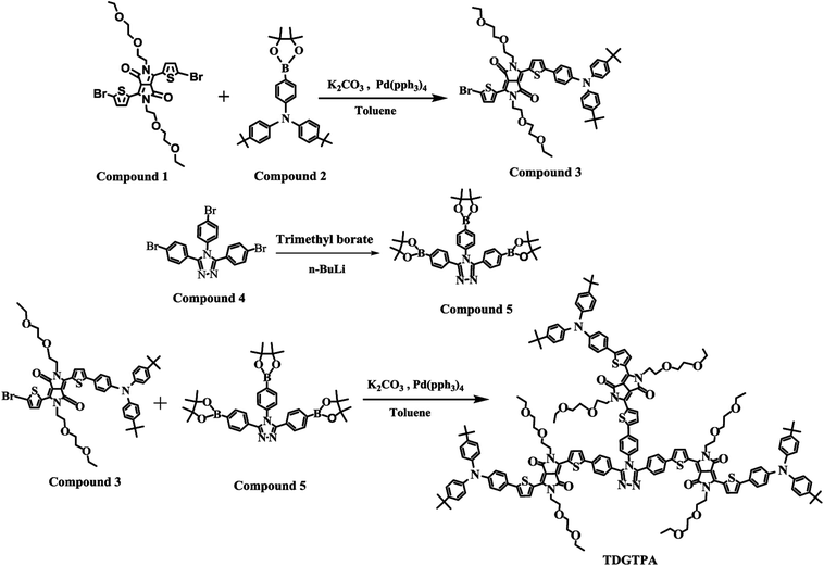 |
| | Scheme 1 Synthesis of 3, 5, and TDGTPA. | |
3-[5-[4-(N,N-Bis(4-tert-butylphenyl)amino)phenyl]thien-2-yl]-2,5-bis(2-(2-ethoxyethoxy)ethyl)-6-(5-bromothien-2-yl)pyrrolo[3,4-c]pyrrole-1,4-dione (3). A solution of 1 (1.00 g, 1.45 mmol), 2 (0.490 g, 1.01 mmol), and Pd(PPh3)4 (0.220 g, 0.200 mmol) in toluene (40 mL) and aqueous K2CO3 (2 M, 10 mL) was heated under reflux with vigorous stirring under a N2 atmosphere for 48 h. After cooling to room temperature, the mixture was partitioned between DCM and water. The organic phase was collected, dried (MgSO4), filtered, and evaporated to dryness. The crude product was purified through column chromatography (SiO2; DCM/acetone) to give a deep-purple solid (0.37 g, 39%). 1H NMR spectrum of compound 3 has been shown in Fig. S1.† 1H NMR (600 MHz, CDCl3, TMS): δ 1.12–1.19 (m, 6H), 1.33 (s, 18H), 3.43–3.49 (m, 4H), 3.51–3.56 (m, 4H), 3.61–3.67 (m, 4H), 3.78–3.82 (m, 4H), 4.20 (t, J = 6.0 Hz, 2H), 4.31 (t, J = 6.0 Hz, 2H), 7.03 (d, J = 9.0 Hz, 2H), 7.07 (d, J = 9.0 Hz, 2H), 7.19 (d, J = 4.2 Hz, 1H), 7.30 (d, J = 8.4 Hz, 2H), 7.35 (d, J = 4.2 Hz, 1H), 7.52 (d, J = 8.4 Hz, 2H), 8.44 (d, J = 4.2 Hz, 1H), 8.90 (d, J = 4.2 Hz, 1H). 13C NMR (150 MHz, CDCl3): δ 15.1, 30.9, 31.4, 34.4, 41.8, 42.2, 66.7, 69.0, 69.7, 70.8, 107.3, 108.4, 110.0, 118.4, 121.7, 123.3, 124.7, 125.5, 126.2, 127.0, 127.1, 131.1, 134.1, 137.3, 137.8, 141.2, 144.2, 146.7, 149.1, 151.4, 161.2, 161.7, 207.0. Anal. calcd for C52H60N3O6S2Br: C, 64.60; H, 6.21; N, 4.35; O, 9.94; S, 6.62. Found: C, 64.58; H, 6.20; N, 4.38; O, 9.90; S, 6.66.
3,4,5-Tris(4-(4,4,5,5-tetramethyl-1,3,2-dioxaborolan-2-yl)phenyl)-4H-1,2,4-triazole (5). A solution of 4 (4.37 g, 8.18 mmol) in dry THF (40 mL) was stirred at −78 °C under a N2 atmosphere for 20 min and then n-BuLi (2.5 M in hexane, 5.24 mL, 13.1 mmol) was added dropwise. The mixture was maintained at −78 °C with stirring for a further 2.5 h, at which point trimethyl borate (1.47 mL, 13.0 mmol) was added dropwise. The mixture was warmed to room temperature and stirred for 12 h, then HCl (1 N) was added to quench the reaction. The mixture was concentrated using a rotary evaporator. The residue was partitioned between DCM and water; the organic phase was dried (MgSO4), filtered, and evaporated to dryness. The residue was recrystallized (MeOH) to provide a white solid (2.70 g, 48.9%). 1H NMR spectrum of compound 5 has been shown in Fig. S2.† 1H NMR (CDCl3, 600 MHz, δ/ppm): 1.33 (s, 24H), 1.37 (s, 12H), 7.09 (d, J = 8.4 Hz, 2H), 7.39 (d, J = 7.8 Hz, 4H), 7.71 (d, J = 8.4 Hz, 4H), 7.80 (d, J = 8.4 Hz, 2H). 13C NMR (150 MHz, CDCl3): δ 10.5, 14.0, 23.0, 23.6, 28.3, 28.4, 29.7, 30.1, 31.4, 34.4, 39.1, 46.0, 121.6, 123.2, 124.7, 125.4, 126.3, 126.8, 128.5, 131.3, 134.6, 138.0, 141.3, 144.2, 146.7, 149.0, 151.0, 161.6, 161.9. Anal. calcd for C38H48N3O6B3: C, 67.62; H, 7.12; N, 6.23; O, 14.23. Found: C, 67.60; H, 7.15; N, 6.20; O, 14.26.
TDGTPA. A solution of 3 (1.00 g, 1.05 mmol), 5 (0.175 g, 0.260 mmol), and Pd(PPh3)4 (0.220 g, 0.200 mmol) in toluene (40 mL) and aqueous K2CO3 (2 M, 10 mL) was heated under reflux with vigorous stirring under a N2 atmosphere for 48 h. After cooling to room temperature, the toluene was evaporated under vacuum. The resulting mixture was partitioned between DCM and water. The organic phase was collected, dried (MgSO4), filtered, and evaporated to dryness. The crude product was purified through column chromatography (SiO2; DCM/acetone) to give a deep-purple solid (0.114 g, 15%) having values of Tg, TC, and Tm of 48.0, 126.4, and 192.7 °C, respectively. 1H NMR spectrum of TDGTPA has been shown in Fig. S3.† 1H NMR (CDCl3, 600 MHz, δ/ppm): 1.12–1.19 (m, 18H), 1.32 (s, 54H), 3.43–3.49 (m, 12H), 3.51–3.56 (m, 12H), 3.61–3.67 (m, 12H), 3.78–3.81 (m, 12H), 4.20 (t, J = 6.0 Hz, 6H), 4.31 (t, J = 6.0 Hz, 6H), 7.04 (d, J = 9 Hz, 12H), 7.05–7.09 (m, 8H), 7.30 (d, J = 9 Hz, 12H), 7.35 (d, J = 4.2 Hz, 3H), 7.44 (t, J = 6.0 Hz, 3H), 7.52 (d, J = 9 Hz, 6H), 7.60 (d, J = 4.2, 4H), 7.70 (d, J = 8.4 Hz, 4H), 7.90 (d, J = 8.4 Hz, 2H), 8.70 (d, J = 3.6 Hz, 3H), 8.75 (d, J = 4.2 Hz, 3H), 8.88 (d, J = 4.2 Hz, 3H), 8.97 (d, J = 4.2 Hz, 3H). 13C NMR spectrum of TDGTPA has been shown in Fig. S4.† 13C NMR (150 MHz, CDCl3): δ 14.1, 15.1, 22.7, 29.7, 31.9, 34.4, 41.9, 65.9, 66.2, 66.7, 68.9, 70.0, 70.7, 107.4, 108.2, 110.0, 121.0, 121.8, 123.2, 124.6, 125.5, 126.2, 127.0, 127.2, 128.4, 128.8, 129.8, 130.4, 130.9, 134.2, 137.1, 139.0, 140.8, 142.1, 144.1, 144.2, 146.6, 146.8, 149.0, 151.0, 161.4, 161.8, 167.7. Anal. calcd for C176H192N12O18S6 (2952) C, 71.54; H, 6.50; N, 5.69; O, 9.76; S, 6.50. Found: C, 71.56; H, 6.47; N, 5.71; O, 9.75; S, 6.51.
2.3 Fabrication and characterization of inverted PSCs
The inverted PSCs in this study were based on the structure ITO-coated glass/ZnO/interfacial layer/photoactive layer/MoO3 (5 nm)/Ag (50 nm), with the photoactive layer comprising an interpenetrating network of P3HT/PC71BM. ITO-coated glass (sheet resistance: 15 Ω per square) was purchased from Applied Film Corp. PC71BM was purchased from Nano-Carbon and used as received. The ITO substrates were patterned lithographically, cleaned with detergent, ultra-sonicated in acetone and isopropyl alcohol, dried on a hot plate (120 °C, 5 min), and then treated with oxygen plasma (15 min). The ZnO precursor solution was spin-cast on a pre-cleaned ITO-glass substrate and annealed (200 °C, 1 h) to give a ZnO film having a thickness of 30 nm, as determined using a profilometer. A solution of TDGTPA (0.1 wt%) in o-DCB was then spin-coated (2000 rpm) onto the ZnO-coated substrates to afford a bilayer film after annealing (80 °C, 30 min). A solution of P3HT/PC71BM (1![[thin space (1/6-em)]](https://www.rsc.org/images/entities/char_2009.gif) :
:![[thin space (1/6-em)]](https://www.rsc.org/images/entities/char_2009.gif) 1, w/w; 20 mg mL−1) in o-DCB was stirred overnight, filtered through a 0.2 mm polytetrafluoroethylene filter, and then spin-coated (1000 rpm, 60 s) onto the TDGTPA-based interfacial layer to form the P3HT/PC71BM film-based photoactive layer. The thickness of the photoactive layer was approximately 90 nm. Subsequently, a thin layer of MoO3 (thickness: ca. 10 nm) was vacuum-deposited on top of the photoactive layer at an evaporation rate of 0.1 Å s−1. The top Ag electrode (100 nm) was thermally deposited through a shade mask having an effective device area of 0.04 cm2. After electrode deposition, the inverted PSC was encapsulated. The cathode deposition rate was determined using a quartz thickness monitor (STM-100/MF, Sycon). The thicknesses of the thin films were determined using a surface texture analysis system (3030ST, Dektak). The PV properties of the inverted PSCs were measured using a programmable electrometer equipped with current and voltage sources (Keithley 2400) under illumination with solar-simulating light (100 mW cm−2) from an AM1.5 solar simulator (NewPort Oriel 96000).
1, w/w; 20 mg mL−1) in o-DCB was stirred overnight, filtered through a 0.2 mm polytetrafluoroethylene filter, and then spin-coated (1000 rpm, 60 s) onto the TDGTPA-based interfacial layer to form the P3HT/PC71BM film-based photoactive layer. The thickness of the photoactive layer was approximately 90 nm. Subsequently, a thin layer of MoO3 (thickness: ca. 10 nm) was vacuum-deposited on top of the photoactive layer at an evaporation rate of 0.1 Å s−1. The top Ag electrode (100 nm) was thermally deposited through a shade mask having an effective device area of 0.04 cm2. After electrode deposition, the inverted PSC was encapsulated. The cathode deposition rate was determined using a quartz thickness monitor (STM-100/MF, Sycon). The thicknesses of the thin films were determined using a surface texture analysis system (3030ST, Dektak). The PV properties of the inverted PSCs were measured using a programmable electrometer equipped with current and voltage sources (Keithley 2400) under illumination with solar-simulating light (100 mW cm−2) from an AM1.5 solar simulator (NewPort Oriel 96000).
3. Results and discussion
3.1 Chemical and thermal characterization of TDGTPA
As displayed in Scheme 1, the conjugated branched compound 3 was synthesized through Suzuki coupling of the 2,5-thienyl diketopyrrolopyrrole dibromide 1 and the tert-butyl-substituted triphenylamino boronic ester 2. TDGTPA was then obtained through Suzuki coupling of the bromide 3 with the triazole tris(boronic ester) 5. The chemical structure of TDGTPA was confirmed using 1H NMR spectroscopy and elemental analysis. TDGTPA is soluble in common organic solvents, including o-DCB, chlorobenzene, DCM, CHCl3, and THF. Such excellent solubility suggested favorable spin-coating of TDGTPA on the ZnO layer. We used DSC and TGA to determine the thermal properties of TDGTPA (Fig. 1). The transition temperatures were determined from the second round of the DSC heating scan. A glass transition temperature (Tg), a recrystallization temperature (TC), and a melting temperature (Tm) were all observed for TDGTPA: 47.5, 126.4, and 192.6 °C, respectively. In addition, the value of Td for TDGTPA was 310 °C. Such a high thermal stability suggested that this compound might be suitable for PSC applications.
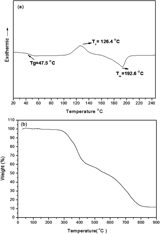 |
| | Fig. 1 DSC and TGA thermograms of TDGTPA. | |
3.2 Optical properties of TDGTPA
Fig. 2 presents normalized UV-Vis absorption spectra of TDGTPA as a solution in o-DCB and as a solid film. In the o-DCB solution, the spectrum of TDGTPA exhibited an absorption band at 600 nm, representing intramolecular charge transfer (ICT) between the triphenylamine donor units and the diketopyrrolopyrrole-based branches. The maximal absorption wavelength of TDGTPA in the thin film state appeared at 604 nm; that is, it was not significantly red-shifted relative to the signal of the sample in o-DCB. We suspect that the presence of three diketopyrrolopyrrole-based branches having bulky structures resulted in spatial non-coplanarity of the triazole core with respect to these three arms. Accordingly, the degree of π-stacking of the branches was low and, therefore, the red-shift of the maximum absorption wavelengths in thin film state was not significant for TDGTPA.37–39 Nevertheless, the full width at half maximum (FWHM) of the absorption band of TDGTPA in the film state was greater than that of the sample in solution, suggesting that the conformation of the SSM in the thin film was more complex than that in solution. We determined the band gap energy (Eg) of TDGTPA in the thin film state from the onset wavelength (740 nm) of the absorption band, obtaining a value of 1.68 eV. Presumably, charge transfer between the triazole core and the conjugated branches resulted in this relatively low value of Eg for TDGTPA.
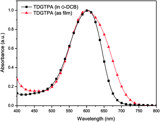 |
| | Fig. 2 Normalized UV-Vis absorption spectra of TDGTPA in solution and as a thin film. | |
3.3 Electrochemical properties of TDGTPA
We used CV to investigate the electrochemical behavior of TDGTPA and to estimate the energy level of its highest occupied molecular orbital (HOMO). Fig. 3 reveals the oxidation behavior of TDGTPA in the CV curve. The oxidation potential (Eoxon) of TDGTPA was 0.56 V vs. Ag/Ag+. Based on this value, we calculated the HOMO energy level of TDGTPA according to the equation:37–39
| HOMO = –e(Eoxon − Eoxon, ferrocene + 4.8) (eV) |
where 4.80 eV is the energy level of ferrocene below the vacuum level and the value of Eoxon of ferrocene/ferrocene+ is 0.09 V in 0.1 M Bu4NClO4/MeCN. Accordingly, we obtained a HOMO energy level for TDGTPA of −5.36 eV. We suspect that the relatively high degree of electron delocalization along the diketopyrrolopyrrole-based conjugated branches led to a relatively low value of Eoxon and the relatively high HOMO energy level of TDGTPA. Because no evidence for reversible n-doping was apparent in the CV spectra, we estimated the LUMO energy level from the HOMO energy level and the value of Eg obtained from the UV-Vis absorption spectra, using the equation
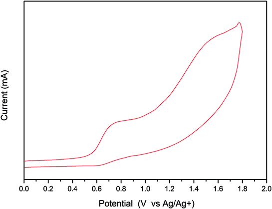 |
| | Fig. 3 Cyclic voltammogram of TDGTPA. | |
This approach gave a LUMO energy level of −3.98 eV for TDGTPA. We attribute this relatively low LUMO energy level to the high content of electron-deficient moieties (diketopyrrolopyrrole, triazole) in the SSM. We suspected that such a low LUMO energy level would, however, be favorable for electron transfer from the P3HT/PC71BM-based photoactive layer to the electron-transporting ZnO layer when we used TDGTPA as the electron-selective layer in inverted PSCs. Apart from that, CV spectrum were measured with 30 runs of scan to study the reversibility and electrochemical stability of TDGTPA (Fig. S5†). The intensity of the CV peak slightly decreased for the first five runs of scan and then remained unchanged for the further runs of scan. CV spectra indicate that the TDGTPA exhibited good electrochemical stability.
3.4 Morphology of TDGTPA-coated ZnO
The electron-injection capacity and PV performance of an inverted PSC are strongly dependent on the morphology of its ZnO layer. We used AFM (topographic and phase-contrast images) to investigate the surface morphologies of TDGTPA-coated ZnO layers. As revealed in Fig. 4(a) and (b), the surface roughness of the ZnO layer was 5.2 nm. The surface roughness decreased after TDGTPA (0.1 wt%) was coated (thickness: 10–20 nm) onto the ZnO layer. Indeed, the surface morphology of the ZnO layer was influenced after modification with TDGTPA. Nevertheless, high surface areas remained for the TDGTPA-coated ZnO layers. A large contact area would favor electron transfer from the photoactive layer to the ZnO layer. Next, we coated the surfaces of the ZnO and TDGTPA-modified ZnO layers with the P3HT/PC71BM (1![[thin space (1/6-em)]](https://www.rsc.org/images/entities/char_2009.gif) :
:![[thin space (1/6-em)]](https://www.rsc.org/images/entities/char_2009.gif) 1, w/w) blend-based photoactive layer. Fig. 5 presents the corresponding topographic and phase-contrast AFM images. The phase images indicate that the PC71BM and P3HT units were phase-separated on the nanoscale on the surfaces of both the ZnO and TDGTPA-modified ZnO layers. This phase separation was more obvious for the P3HT/PC71BM blend film coated on the TDGTPA-modified ZnO layer. Because the PV performance of bulk heterojunction solar cells is strongly dependent on the morphology of the P3HT/PC71BM blend film, the P/N heterojunction phase must be controlled at the nanoscale level to avoid recombination of excitons.37–39 A certain degree of phase separation is crucial for the efficient formation of free carriers to provide PSCs with optimal PV properties. Furthermore, the presence of a large surface area for the photoactive layer favors hole transfer from the photoactive layer to the anode electrode.
1, w/w) blend-based photoactive layer. Fig. 5 presents the corresponding topographic and phase-contrast AFM images. The phase images indicate that the PC71BM and P3HT units were phase-separated on the nanoscale on the surfaces of both the ZnO and TDGTPA-modified ZnO layers. This phase separation was more obvious for the P3HT/PC71BM blend film coated on the TDGTPA-modified ZnO layer. Because the PV performance of bulk heterojunction solar cells is strongly dependent on the morphology of the P3HT/PC71BM blend film, the P/N heterojunction phase must be controlled at the nanoscale level to avoid recombination of excitons.37–39 A certain degree of phase separation is crucial for the efficient formation of free carriers to provide PSCs with optimal PV properties. Furthermore, the presence of a large surface area for the photoactive layer favors hole transfer from the photoactive layer to the anode electrode.
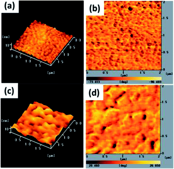 |
| | Fig. 4 Tapping-mode AFM (a and c) topographic and (b and d) phase images of (a and b) ZnO and (c and d) TDGTPA-modified ZnO layers. | |
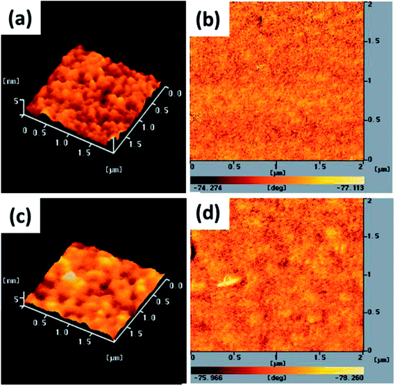 |
| | Fig. 5 Tapping-mode AFM (a and c) topographic and (b and d) phase images of P3HT/PC71BM (1![[thin space (1/6-em)]](https://www.rsc.org/images/entities/char_2009.gif) : :![[thin space (1/6-em)]](https://www.rsc.org/images/entities/char_2009.gif) 1, w/w) blend film-coated (a and b) ZnO and (c and d) TDGTPA-modified ZnO layers. 1, w/w) blend film-coated (a and b) ZnO and (c and d) TDGTPA-modified ZnO layers. | |
3.5 Surface energy of TDGTPA-coated ZnO
The surface energy of ZnO significantly influences the compatibility between the ZnO layer and a conjugated polymer-based photoactive layer.19,49,56 Moreover, the PV performance of inverted PSCs is closely related to the surface energy of the ZnO layer. Furthermore, the PV performance is also influenced by the surface energy of the surface-modified ZnO layer. The best PV performance of a P3HT:PC71BM-based inverted PSC was obtained when the surface-modified ZnO layer had an intermediate surface energy of 51 mN m−1.19,56 Thus, we calculated the surface free energies of the ZnO, TDGTPA, and P3HT:PC71BM layers by measuring their contact angles (CAs) to water and glycerol, based on the Wu model (harmonic mean).56 The measured CAs (θ) were used in the following equations to calculate the polar (γp) and dispersive (γd) components of the total energy γtot; here, the subscript “w” refers to deionized water and “Gly” to glycerol:
γw (1 + cos![[thin space (1/6-em)]](https://www.rsc.org/images/entities/char_2009.gif) θw) = [4γdwγd/(γdw + γd)] + [4γpwγp/(γpw + γp)] θw) = [4γdwγd/(γdw + γd)] + [4γpwγp/(γpw + γp)] |
and
γGly (1 + cos![[thin space (1/6-em)]](https://www.rsc.org/images/entities/char_2009.gif) θGly) = [4γdGlyγd/(γdGly + γd)] + [4γpGlyγp/(γpGly + γp)]. θGly) = [4γdGlyγd/(γdGly + γd)] + [4γpGlyγp/(γpGly + γp)]. |
Thus, the total surface energy is
Table 1 summarizes the calculated surface energies. The surface energies of ZnO and P3HT were 74.5 and 20.0 mN m−1, respectively, in good agreement with those reported previously.19,56 The TDGTPA- and TDGTPA/P3HT:PC71BM-coated ZnO films had surface energies of 40.7 and 24.9 mN m−1, respectively. Thus, the surface energy of ZnO decreased significantly after its surface had been modified with a TDGTPA film. This behavior would presumably improve the compatibility of the ZnO layer with the P3HT:PC71BM–based photoactive layer.
Table 1 Contact angles and surface energies of films of ZnO, TDGTPA, P3HT:PC71BM, and TDGTPA/P3HT:PC71BMa
| Film |
θwater (°) |
θglycerol (°) |
γp (mN m−1) |
γd (mN m−1) |
γtot (mN m−1) |
| The measured contact angles, θ, were used with the Wu equation (harmonic mean) to calculate the polar (γp) and dispersive (γd) components of the total energy (γtot). |
| ZnO |
40.9 |
61.2 |
71.3 |
3.2 |
74.5 |
| ZnO/TDGTPA |
68.1 |
56.4 |
20.1 |
20.6 |
40.7 |
| ZnO/P3HT:PC71BM |
97.8 |
90.4 |
10.0 |
11.1 |
21.1 |
| ZnO/TDGTPA/P3HT:PC71BM |
96.2 |
84.6 |
7.6 |
17.3 |
24.9 |
3.6 PV properties of P3HT/PC71BM-based inverted PSCs incorporating TDGTPA as an electron-selective layer
We fabricated inverted PSCs having the structure ITO/ZnO (30 nm)/P3HT:PC71BM/MoO3 (5 nm)/Ag (50 nm), where ITO and Ag functioned as the cathode and anode, respectively. We also prepared structures in which TDGTPA was inserted as the electron-selective layer between the ZnO layer and the photoactive layer. Fig. 6(a) and (b) present schematic representations of the configurations and energy levels of each component in the PSCs. We expected that the low LUMO energy level of TDGTPA would be favorable for electron transfer from the photoactive layer to the ZnO layer. We measured the PV performance of the PSCs under illumination with solar-simulating light (100 mW cm−2) from an AM1.5 solar simulator. Fig. 7 displays the current density–voltage (J–V) characteristics of the inverted PSCs; Table 2 summarizes the photovoltaic parameters. The control bare device exhibited a PCE of 2.92% with an open-circuit voltage (VOC) of 0.63 V, a short-circuit current (JSC) of 8.00 A cm−2, and an FF of 0.58. After the ZnO layer had been modified with TDGTPA, the PV performance of the inverted PSC improved. The incorporation of the TDGTPA afforded increases in the value of JSC (9.09 mA cm−2) and fill factor (0.60). The PCE of the PSC incorporating the ZnO layer modified with TDGTPA was enhanced significantly, to 3.38%—an improvement of 15.8% over that (2.92%) of the bare inverted PSC. The dark current density measurements of the P3HT/PC71BM blend based inverted PSCs have been newly added in Fig. S6.† The dark current density was reduced for the P3HT/PC71BM blend based inverted PSCs by the insertion of a TDGTPA interlayer between ZnO and photoactive layer. This implies that the presence of TDGTPA is favorable for the electron transport from photoactive layer to ZnO layer. In addition, the electron-mobilities were measured by the space charge limited current (SCLC) method with structure of electron-only device ITO/ZnO/Interlayer/P3HT:PC71BM/Al (Fig. S7†). The electron-mobility values are estimated to be 6.85 × 10⁻⁵ and 9.54 × 10⁻⁵ cm2 V−1 S−1, respectively. After the ZnO layer had been modified with TDGTPA, the electron-mobility of the device was improved. Apart from that, the external quantum efficiency (EQE) spectra of these P3HT/PC71BM based inverted PSCs recorded under monochromatic irradiation are shown in Fig. S8.† The maximal EQE value of TDGTPA-incorporated P3HT:PC71BM based inverted PSC was slightly higher than that of the bare inverted PSC. The enhancement of EQE can be attributed to the reduced contact resistance owing to the TDGTPA layer inserted between ZnO and photoactive layers. Accordingly, TDGTPA did indeed play a positive role as an electron-selective layer in the inverted PSC. The addition of TDGTPA decreased the surface roughness of the ZnO layer while also increasing the conductivity and charge transfer capacity at the interface between the ZnO layer and the photoactive layer. Consequently, we observed a higher photocurrent density and a higher PCE for the inverted PSC incorporating the TDGTPA-modified ZnO layer.
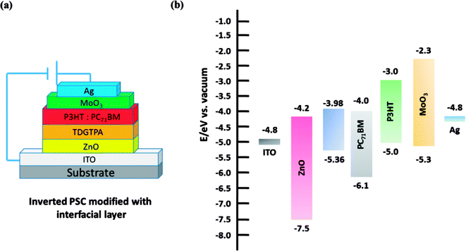 |
| | Fig. 6 (a) Device architecture of the P3HT/PC71BM–based inverted PSCs incorporating TDGTPA as a modifying layer. (b) Schematic representation of the energy levels of the individual components in the inverted PSCs. | |
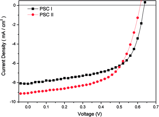 |
| | Fig. 7 Current density–potential characteristics of illuminated (AM 1.5 G, 100 mW cm−2) P3HT/PC71BM-based inverted PSCs. | |
Table 2 Photovoltaic performance of P3HT:PC71BM blend film-based inverted PSCs
| Inverted PSCa |
Electron-selective layer |
Photoactive layer |
VOC (V) |
JSC (mA cm−2) |
FF |
PCE (%) |
| PV properties of illuminated (AM1.5 solar simulator, 100 mW cm−2) P3HT:/PC71BM-based inverted PSCs. |
| PSC I |
— |
P3HT:PC71BM |
0.63 |
8.00 |
0.58 |
2.92 |
| PSC II |
TDGTPA |
P3HT:PC71BM |
0.62 |
9.09 |
0.60 |
3.38 |
In general, the stability of PSCs is mainly affected by the photovoltaic performance of the cell, while the thermal and morphology stability of PSCs is influenced by the P3HT molecular motions in photoactive layer. Nevertheless, the influence of the molecular motions on the thermal stability and morphology of the P3HT:PC71BM blend film would not be significant since the Tg of P3HT:PC71BM blend film is higher than 120 °C. DSC thermograms show that the Tgs of P3HT and P3HT:PC71BM blend were observed at around of 127 °C (Fig. S9†). The molecular motions during the glass transition was suppressed for P3HT after blending with PC71BM. Moreover, the topographic and phase images of P3HT:PC71BM blend film indicate that the morphology of photoactive layer was stable after storage in ambient air for 10 days (Fig. S10†). Therefore, we discussed the storage stability of inverted PSCs in ambient conditions under the illumination of a light intensity of 100 mW cm−2 (Fig. 8). The P3HT:PC71BM blend film based inverted PSC with TDGTPA interlayer exhibited better stability than did the inverted PSC without TDGTPA interlayer. This is attributed to lower series resistance and higher photo-conversion efficiency of TDGTPA inserted PSC.
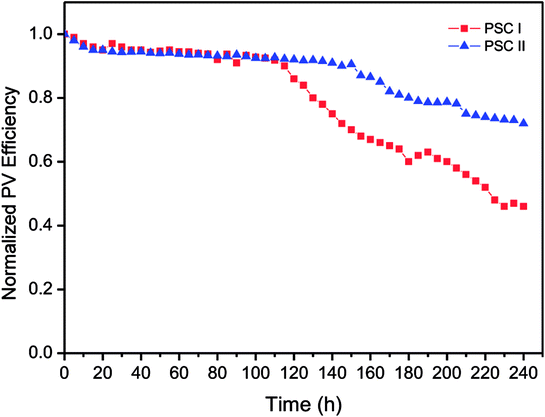 |
| | Fig. 8 Storage stability of P3HT:PC71BM blend film based inverted PSCs with/without TDGTPA interlayer in ambient conditions. | |
4. Conclusion
We have synthesized a novel triazole-cored star-shaped molecule, TDGTPA, presenting 2,5-thienyl diketopyrrolopyrrole derivatives as conjugated branches, and then used it as an electron-selective interlayer in inverted PSCs. The low LUMO energy level of TDGTPA favors electron transfer from the P3HT:PC71BM blend-based photo-conversion layer to the ZnO layer. Moreover, the surface energy of the ZnO layer decreased significantly after its surface was modified with a film of TDGTPA. Such modification improved the compatibility of the ZnO layer and the P3HT:PC71BM-based photoactive layer. As a result, inserting the TDGTPA film as an electron-selective layer enhanced the short-circuit current density and the photo-conversion efficiency of a P3HT:PC71BM blend-based inverted PSC.
Conflicts of interest
There are no conflicts to declare.
Acknowledgements
We thank the Ministry of Science and Technology (MOST) of Taiwan for financial support (grant no. 104-2221-E-005-065-MY3).
References
- Y. Cai, L. Huo and Y. Sun, Adv. Mater., 2017, 29, 1605437 CrossRef PubMed.
- K. E. Hung, C. E. Tsai, S. L. Chang, Y. Y. Lai, U. S. Jeng, F. Y. Cao, C. S. Hsu, C. J. Su and Y. J. Cheng, ACS Appl. Mater. Interfaces, 2017, 9, 43861 CrossRef PubMed.
- Y. Y. Yu, C. H. Chen, C. C. Chueh, C. Y. Chiang, J. H. Hsieh, C. P. Chen and W. C. Chen, ACS Appl. Mater. Interfaces, 2017, 9, 27853 CrossRef PubMed.
- J. Zhang, D. Deng, C. He, Y. He, M. Zhang, Z. G. Zhang, Z. Zhang and Y. Li, Chem. Mater., 2011, 23, 817 CrossRef.
- Y. C. Lin, H. W. Cheng, Y. W. Su, B. H. Lin, Y. J. Lu, C. H. Chen, H. C. Chen, Y. Yang and K. H. Wei, Nano Energy, 2018, 43, 138 CrossRef.
- X. Shi, L. Zuo, S. B. Jo, K. Gao, F. Lin and A. K. Y. Jen, Chem. Mater., 2017, 29, 8369 CrossRef.
- Z. Zhang, L. Feng, S. Xu, J. Yuan, Z. G. Zhang, H. Peng, Y. Li and Y. Zou, J. Mater. Chem. A, 2017, 5, 11286 RSC.
- J. Huang, H. Wang, K. Yan, X. Zhang, H. Chen, C. Z. Li and J. Yu, Adv. Mater., 2017, 29, 1606729 CrossRef PubMed.
- F. C. Krebs and K. Norman, Prog. Photovoltaics, 2007, 15, 697 Search PubMed.
- M. Jorgensen, K. Norman and F. C. Krebs, Sol. Energy Mater. Sol. Cells, 2008, 92, 686 CrossRef.
- H. J. Wang, C. W. Chou, C. P. Chen, Y. H. Chen, R. H. Lee and R. J. Jeng, J. Mater. Chem. A, 2013, 1, 8950 RSC.
- M. J. Tan, S. Zhong, J. Li, Z. Chen and W. Chen, ACS Appl. Mater. Interfaces, 2013, 5, 4696 CrossRef PubMed.
- R. Peng, F. Yang, X. Ouyang, Y. Liu, Y. S. Kim and Z. Ge, Appl. Phys. A, 2014, 114, 429 CrossRef.
- S. K. Hau, H. L. Yip, N. S. Baek, J. Zou, K. O'Malley and A. K. Y. Jen, Appl. Phys. Lett., 2008, 92, 253301 CrossRef.
- Y. M. Sung, F. C. Hsu and Y. F. Chen, Sol. Energy Mater. Sol. Cells, 2014, 125, 239 CrossRef.
- J. Xiong, J. Yang, B. Yang, C. Zhou, X. Hu, H. Xie, H. Huang and Y. Gao, Org. Electron., 2014, 15, 1745 CrossRef.
- Z. Yuan, J. Mater. Sci.: Mater. Electron., 2014, 25, 1289 CrossRef.
- W. Qin, G. Ding, X. Xu, L. Yang and S. Yin, J. Mater. Sci. Technol., 2014, 30, 197 CrossRef.
- Y. A. Su, W. C. Lin, H. J. Wang, W. H. Lee, R. H. Lee, S. A. Dai, C. F. Hsieh and R. J. Jeng, RSC Adv., 2015, 5, 25192 RSC.
- G. K. Mor, K. Shankar, M. Paulose, O. K. Varghese and C. A. Grimes, Appl. Phys. Lett., 2007, 91, 15211 CrossRef.
- Z. Lin, J. Chang, J. Zhang, C. Jiang, J. Wu and C. Zhu, J. Mater. Chem., 2014, 2, 7788 RSC.
- H. Kang, S. Hong, J. Lee and K. Lee, Adv. Mater., 2012, 24, 3005 CrossRef PubMed.
- S. Nam, J. Seo, H. Han, H. Kim, S. G. Hahm, M. Ree, Y. S. Gal, T. D. Anthopoulos, D. D. C. Bradley and Y. Kim, Adv. Mater. Interfaces, 2016, 1600415 CrossRef.
- A. Sharma, R. Kroon, D. A. Lewis, G. G. Andersson and M. R. Andersson, ACS Appl. Mater. Interfaces, 2017, 9, 10929 CrossRef PubMed.
- K. Zhang, R. Xu, W. Ge, M. Qi, G. Zhang, Q. H. Xu, F. Huang, Y. Cao and X. Wang, Nano Energy, 2017, 34, 164 CrossRef.
- S. Dong, Z. Hu, K. Zhang, Q. Yin, X. Jiang, F. Huang and Y. Cao, Adv. Mater., 2017, 29, 1701507 CrossRef PubMed.
- D. Zhou, J. Liu, L. Chen, H. Xu, X. Cheng, F. Wu and Y. Chen, RSC Adv., 2017, 7, 24345 RSC.
- X. Bulliard, S. G. Ihn, S. Yun, Y. Kim, D. Choi, J. Y. Choi, M. Kim, M. Sim, J. H. Park, W. Choi and K. Cho, Adv. Funct. Mater., 2010, 20, 4381 CrossRef.
- P. Fu, X. Guo, S. Wang, Y. Ye and C. Li, Adv. Mater. Interfaces, 2017, 9, 13390 CrossRef PubMed.
- F. Zhu, X. Chen, Z. Lu, J. Yang, S. Huang and Z. Sun, Nano-Micro Lett., 2014, 6, 24 CrossRef.
- S. Cho, K. D. Kim, J. Heo, J. Y. Lee, G. Cha, B. Y. Seo, Y. D. Kim, Y. S. Kim, S. Y. Choi and D. C. Lim, Sci. Rep., 2014, 4, 4306 CrossRef PubMed.
- P. Li, X. Li, C. Sun, G. Wang, J. Li, T. Jiu and J. Fang, Sol. Energy Mater. Sol. Cells, 2014, 126, 36 CrossRef.
- H. Choi, J. Lee, W. Lee, S. J. Ko, R. Yang, J. C. Lee, H. Y. Woo, C. Yang and J. Y. Kim, Org. Electron., 2013, 14, 3138 CrossRef.
- H. L. Yip and A. K. Y. Jen, Energy Environ. Sci., 2012, 5, 5994 RSC.
- J. Li, F. Zhao, T. Wang, M. Nie, J. Li, Z. Wei, L. Jiang and C. Wang, J. Mater. Chem. A, 2017, 5, 947 RSC.
- J. Zhen, Q. Liu, X. Chen, D. Li, Q. Qiao, Y. Lu and S. Yang, J. Mater. Chem. A, 2016, 4, 8072 RSC.
- C. Y. Huang, W. H. Lee and R. H. Lee, RSC Adv., 2014, 4, 48150 RSC.
- S. Y. Shiau, C. H. Chang, W. J. Chen, H. J. Wang, R. J. Jeng and R. H. Lee, Dyes Pigm., 2015, 115, 35 CrossRef.
- Y. W. Kao, W. H. Lee, R. J. Jeng, C. F. Huang and J. Y. Wu, Mater. Chem. Phys., 2015, 163, 138 CrossRef.
- W. Xu, Z. Kan, T. Ye, L. Zhao, W. Y. Lai, R. Xia, G. Lanzani, P. E. Keivanidis and W. Huang, ACS Appl. Mater. Interfaces, 2015, 7, 452 CrossRef PubMed.
- Y. Zou, Z. He, B. Zhao, Y. Liu, C. Yang, H. Wu and Y. Cao, Sci. Rep., 2015, 5, 17329 CrossRef PubMed.
- C. He, C. Zhong, H. Wu, R. Yang, W. Yang, F. Huang, G. C. Bazan and Y. Cao, J. Mater. Chem., 2010, 20, 2617 RSC.
- Y. Liu, W. Zhang, G. Xie, X. Zeng, J. Fang and C. Yang, J. Mater. Chem. C, 2016, 4, 11278 RSC.
- W. Wei, C. Zhang, D. Chen, Z. Wang, C. Zhu, J. Zhang, X. Lu and Y. Hao, ACS Appl. Mater. Interfaces, 2013, 5, 13318 CrossRef PubMed.
- J. Y. Chen, H. C. Wu, Y. C. Chiu and W. C. Chen, Adv. Energy Mater., 2014, 1301665 CrossRef.
- X. Zhang, C. Liu, Z. Li, J. Guo, L. Shen, W. Guo, L. Zhang, S. Ruan and Y. Long, Chem. Eng. J., 2017, 315, 621 CrossRef.
- X. Zhang, J. Guo, F. Lu, H. Wu, T. Luan, L. Shen and W. Guo, J. Phys. Chem. C, 2018, 122, 10706 CrossRef.
- X. L. Li, H. Ye, D. C. Chen, K. K. Liu, G. Z. Xie, Y. F. Wang, C. C. Lo, A. Lien, J. Peng, Y. Cao and S. J. Su, Isr. J. Chem., 2014, 54, 971 CrossRef.
- B. H. Jiang, Y. J. Peng and C. P. Chen, J. Mater. Chem. A, 2017, 5, 10424 RSC.
- S. Shao, K. Zheng, T. Pullerits and F. Zhang, ACS Appl. Mater. Interfaces, 2013, 5, 380 CrossRef PubMed.
- D. Zhou, X. Cheng, H. Xu, H. Yang, H. Liu, F. Wu, L. Chen and Y. Chen, J. Mater. Chem. A, 2016, 4, 18478 RSC.
- D. Zhou, J. Liu, L. Chen, H. Xu, X. Cheng, F. Wu and Y. Chen, RSC Adv., 2017, 7, 24345 RSC.
- R. H. Lee, L. C. Yang, J. Y. Wu and R. J. Jeng, RSC Adv., 2017, 7, 1016 RSC.
- H. J. Wang, J. Y. Tzeng, C. W. Chou, C. Y. Huang, R. H. Lee and R. J. Jeng, Polym. Chem., 2013, 4, 506 RSC.
- S. H. Chen, C. S. Shiau, L. R. Tsai and Y. Chen, Polymer, 2006, 47, 8436 CrossRef.
- X. Bulliard, S. G. Ihn, S. Yun, Y. Kim, D. Choi, J. Y. Choi, M. Kim, M. Sim, J. H. Park, W. Choi and K. Cho, Adv. Funct. Mater., 2010, 20, 4381 CrossRef.
Footnote |
| † Electronic supplementary information (ESI) available. See DOI: 10.1039/c8ra05360j |
|
| This journal is © The Royal Society of Chemistry 2018 |
Click here to see how this site uses Cookies. View our privacy policy here.  Open Access Article
 *b,
Bo-Tau Liuc,
Ru-Jong Jeng
 d and
Rong-Ho Lee
 *a
*a
![[thin space (1/6-em)]](https://www.rsc.org/images/entities/char_2009.gif) :
:![[thin space (1/6-em)]](https://www.rsc.org/images/entities/char_2009.gif) 1, w/w; 20 mg mL−1) in o-DCB was stirred overnight, filtered through a 0.2 mm polytetrafluoroethylene filter, and then spin-coated (1000 rpm, 60 s) onto the TDGTPA-based interfacial layer to form the P3HT/PC71BM film-based photoactive layer. The thickness of the photoactive layer was approximately 90 nm. Subsequently, a thin layer of MoO3 (thickness: ca. 10 nm) was vacuum-deposited on top of the photoactive layer at an evaporation rate of 0.1 Å s−1. The top Ag electrode (100 nm) was thermally deposited through a shade mask having an effective device area of 0.04 cm2. After electrode deposition, the inverted PSC was encapsulated. The cathode deposition rate was determined using a quartz thickness monitor (STM-100/MF, Sycon). The thicknesses of the thin films were determined using a surface texture analysis system (3030ST, Dektak). The PV properties of the inverted PSCs were measured using a programmable electrometer equipped with current and voltage sources (Keithley 2400) under illumination with solar-simulating light (100 mW cm−2) from an AM1.5 solar simulator (NewPort Oriel 96000).
1, w/w; 20 mg mL−1) in o-DCB was stirred overnight, filtered through a 0.2 mm polytetrafluoroethylene filter, and then spin-coated (1000 rpm, 60 s) onto the TDGTPA-based interfacial layer to form the P3HT/PC71BM film-based photoactive layer. The thickness of the photoactive layer was approximately 90 nm. Subsequently, a thin layer of MoO3 (thickness: ca. 10 nm) was vacuum-deposited on top of the photoactive layer at an evaporation rate of 0.1 Å s−1. The top Ag electrode (100 nm) was thermally deposited through a shade mask having an effective device area of 0.04 cm2. After electrode deposition, the inverted PSC was encapsulated. The cathode deposition rate was determined using a quartz thickness monitor (STM-100/MF, Sycon). The thicknesses of the thin films were determined using a surface texture analysis system (3030ST, Dektak). The PV properties of the inverted PSCs were measured using a programmable electrometer equipped with current and voltage sources (Keithley 2400) under illumination with solar-simulating light (100 mW cm−2) from an AM1.5 solar simulator (NewPort Oriel 96000).
![[thin space (1/6-em)]](https://www.rsc.org/images/entities/char_2009.gif) :
:![[thin space (1/6-em)]](https://www.rsc.org/images/entities/char_2009.gif) 1, w/w) blend-based photoactive layer. Fig. 5 presents the corresponding topographic and phase-contrast AFM images. The phase images indicate that the PC71BM and P3HT units were phase-separated on the nanoscale on the surfaces of both the ZnO and TDGTPA-modified ZnO layers. This phase separation was more obvious for the P3HT/PC71BM blend film coated on the TDGTPA-modified ZnO layer. Because the PV performance of bulk heterojunction solar cells is strongly dependent on the morphology of the P3HT/PC71BM blend film, the P/N heterojunction phase must be controlled at the nanoscale level to avoid recombination of excitons.37–39 A certain degree of phase separation is crucial for the efficient formation of free carriers to provide PSCs with optimal PV properties. Furthermore, the presence of a large surface area for the photoactive layer favors hole transfer from the photoactive layer to the anode electrode.
1, w/w) blend-based photoactive layer. Fig. 5 presents the corresponding topographic and phase-contrast AFM images. The phase images indicate that the PC71BM and P3HT units were phase-separated on the nanoscale on the surfaces of both the ZnO and TDGTPA-modified ZnO layers. This phase separation was more obvious for the P3HT/PC71BM blend film coated on the TDGTPA-modified ZnO layer. Because the PV performance of bulk heterojunction solar cells is strongly dependent on the morphology of the P3HT/PC71BM blend film, the P/N heterojunction phase must be controlled at the nanoscale level to avoid recombination of excitons.37–39 A certain degree of phase separation is crucial for the efficient formation of free carriers to provide PSCs with optimal PV properties. Furthermore, the presence of a large surface area for the photoactive layer favors hole transfer from the photoactive layer to the anode electrode.


![[thin space (1/6-em)]](https://www.rsc.org/images/entities/char_2009.gif) :
:![[thin space (1/6-em)]](https://www.rsc.org/images/entities/char_2009.gif) 1, w/w) blend film-coated (a and b) ZnO and (c and d) TDGTPA-modified ZnO layers.
1, w/w) blend film-coated (a and b) ZnO and (c and d) TDGTPA-modified ZnO layers.![[thin space (1/6-em)]](https://www.rsc.org/images/entities/char_2009.gif) θw) = [4γdwγd/(γdw + γd)] + [4γpwγp/(γpw + γp)]
θw) = [4γdwγd/(γdw + γd)] + [4γpwγp/(γpw + γp)]![[thin space (1/6-em)]](https://www.rsc.org/images/entities/char_2009.gif) θGly) = [4γdGlyγd/(γdGly + γd)] + [4γpGlyγp/(γpGly + γp)].
θGly) = [4γdGlyγd/(γdGly + γd)] + [4γpGlyγp/(γpGly + γp)].


