 Open Access Article
Creative Commons Attribution 3.0 Unported Licence
Advanced binder-free electrodes based on CoMn2O4@Co3O4 core/shell nanostructures for high-performance supercapacitors†
Xiaobo Chen *a,
Xiao Liua,
Yongxu Liua,
Yameng Zhua,
Guoce Zhuanga,
Wei Zhenga,
Zhenyu Caia and
Peizhi Yang
 *b
*b
aSchool of New Energy and Electronic Engineering, Yancheng Teachers University, Yancheng, 224051, PR China. E-mail: chenxbok@126.com
bKey Laboratory of Education Ministry for Advance Technique and Preparation of Renewable Energy Materials, Yunnan Normal University, Kunming, 650500, PR China. E-mail: pzhyang@hotmail.com
First published on 10th September 2018
Abstract
Three-dimensional (3D) hierarchical CoMn2O4@Co3O4 core/shell nanoneedle/nanosheet arrays for high-performance supercapacitors were designed and synthesized on Ni foam by a two-step hydrothermal route. The hybrid nanostructure exhibits much more excellent capacitive behavior compared with either the pristine CoMn2O4 nanoneedle arrays alone or Co3O4 nanosheets alone. The formation of an interconnected pore hybrid system is quite beneficial for the facile electrolyte penetration and fast electron transport. The CoMn2O4@Co3O4 electrode can achieve a high specific capacitance of 1627 F g−1 at 1 A g−1 and 1376 F g−1 at 10 A g−1. In addition, an asymmetric supercapacitor (ASC) was assembled by using the CoMn2O4@Co3O4 core/shell hybrid nanostructure arrays on Ni foam as a positive electrode and activated carbon as a negative electrode in an aqueous 3 M KOH electrolyte. A specific capacitance of 125.8 F g−1 at 1 A g−1 (89.2% retention after 5000 charge/discharge cycles at a current density of 2 A g−1) and a high energy density of 44.8 W h kg−1 was obtained. The results indicate that the obtained unique integrated CoMn2O4@Co3O4 nanoarchitecture may show great promise as ASC electrodes for potential applications in energy storage.
1. Introduction
Supercapacitors have attracted a lot of attention due to their ultrafast charge–discharge capability, reversibility, safe operation, long cycle life, high power density and environmental friendliness.1–3 Supercapacitors are usually divided into two categories according to their energy storage behavior: electrical double-layer capacitors (EDLCs) and pseudocapacitors.4,5 Among them, pseudocapacitors exhibit higher specific capacitance due to the fast and fully reversible faradaic redox reactions at the interface between the electrode and electrolyte. As electrode materials for pseudocapacitors, transition metal oxides including Co3O4 and MnO2 and their related compounds have been widely studied.6–12Recently, manganese-based transitional metal oxides (such as CoMn2O4) have emerged as a promising electrode material for supercapacitors due to their high reversible capacities and eco-benignity.13 Jiang et al. synthesized hierarchical nanosheets of CoMn2O4 on Ni foam using a hydrothermal method, which exhibited a high capacitance of 840 F g−1 at 10 A g−1 and retained 102% of its initial capacitance after 7000 cycles.14 Ren et al. fabricated flowerlike microspheres of CoMn2O4, and it showed the specific capacitance of 188 F g−1 at 1 A g−1 with a capacitance retention of 93% after 1000 cycles.15 However, the experimental values of the capacitance are appreciably lower than the theoretical ones as has already been observed. There is a great need and a challenge to enhance the capacitive performance of CoMn2O4. Three-dimensional (3D) nanostructured electrodes have been intensively studied as attractive candidates for electrodes of high-performance supercapacitors due to their unique morphological architectures and super electrochemical properties,16–18 and especially unique porous 3D core/shell nanostructures usually exhibit novel physicochemical properties.19–21 Therefore, intensive research efforts have been expended to design 3D core/shell nanostructured electrodes to shorten diffusion length of electrolytes to interior surfaces. Cai et al. fabricated 3D Co3O4@NiMoO4 core/shell nanowire arrays via a facile two-step hydrothermal method. The material showed excellent electrochemical performance with a remarkable areal capacitance of 5.69 F cm−2 (1094 F g−1) at a current density of 30 mA cm−2.22 Liu et al. fabricated Co3O4@MnO2 core/shell hierarchical nanowire arrays and showed remarkably improved electrochemical performance (about 4 to 10 times increase in areal capacitance with respect to single Co3O4 array).23 Therefore, taking into account the above-mentioned consideration, it is therefore of great possibility to the rational design and fabrication of CoMn2O4@Co3O4 core/shell hybrid nanostructure arrays as electrode materials with combined properties of large areal capacitance and rate capability for high performance pseudocapacitor applications.
In this paper, CoMn2O4@Co3O4 core/shell hybrid nanostructure arrays on Ni foam with unique hierarchical nanostructure for supercapacitor applications were successfully prepared via a facile hydrothermal method. The CoMn2O4@Co3O4 core/shell hybrid nanostructure arrays provides a large surface area and a number of electrochemical reactive sites, and faster ion diffusion and electron transport at electrode/electrolytes interface compared with single CoMn2O4 nanoneedles arrays or Co3O4 nanosheets electrode. Therefore, such interconnected core/shell hybrid network configuration can effectively increase capacitance and cycling stability. The CoMn2O4@Co3O4 hybrid electrodes presented herein exhibited remarkable electrochemical performance for SCs. The CoMn2O4@Co3O4//AC ASC device also exhibits high specific energy and energy density. These results suggest that the CoMn2O4@Co3O4 core/shell hybrid nanostructure arrays can act as a high performance electrode material for SCs applications.
2. Experimental
2.1. Materials
The urea, ethylene glycol, Co(NO3)2·6H2O, Mn(CH3COO)2·4H2O, NH4F and Co(CH3COO)2·4H2O are analytical grade without further purification and purchased from Zhanyun Chemical Co., Ltd., Shanghai, China. Besides, active carbon (AC) was purchased from Tanfeng Tech. Inc (Suzhou, China) with a surface area of 2100 m2 g−1.2.2. Synthesis of CoMn2O4 nanoneedles arrays
In a typical process, firstly, commercially available Ni foam was pretreated with acetone, 3 M HCl solution, deionized water, and ethanol in sequence, and kept in vacuum oven at 60 °C for 6 h. To obtain a homogeneous precursor solution, 2.10 g of Co(NO3)2·6H2O, 3.48 g of Mn(CH3COO)2·4H2O, 5.07 g of urea and 1.63 g of NH4F were dissolved into the 70 mL ethanol under magnetic stirring. The total volume was then made up to 350 mL by adding distilled water and transferred to a Teflon-lined stainless steel autoclave. Then, the well-cleaned Ni foam (1 × 1 cm2 in sizes) was immersed in the autoclave. Subsequently, the autoclave was sealed and placed in an electrical oven at 160 °C for 16 h. After reaction and cooled to room temperature, the precursor deposited Ni foam was taken out and cleaned with ethanol and deionized water, then dried in a vacuum furnace at 60 °C for 6 h. The dried sample was then calcined in air at 400 °C with the heating rate of 10 °C min−1 and kept for 3 h (deposition weight = 3.5 mg cm−2).2.3. Synthesis of CoMn2O4@Co3O4 core/shell hybrid nanostructure arrays
The CoMn2O4 nanoneedles arrays were used as the skeleton for the growth of Co3O4 nanosheets shell, which were synthesized by a simple hydrothermal method. Firstly, 0.8 g of Co(CH3COO)2·4H2O was were dissolved in 35 mL ethylene glycol/H2O (6![[thin space (1/6-em)]](https://www.rsc.org/images/entities/char_2009.gif) :
:![[thin space (1/6-em)]](https://www.rsc.org/images/entities/char_2009.gif) 1) mixed solvent and stirring for 30 min at room-temperature. Then, 0.6 g of sodium dodecyl sulfate as a surfactant was added under stirring. Afterwards, this solution was transferred into a Teflon-lined stainless steel autoclave and heated in an oven at 180 °C for 12 h and then cooled to room temperature. Finally, the solid product was washed with deionized water. Then, the precursor was dried at 60 °C and calcined at 300 °C for 3 h in air to obtain CoMn2O4@Co3O4. The mass loading of CoMn2O4@Co3O4 was 4.6 mg, corresponding with the gain weight of Ni foam. For comparison, the sole Co3O4 nanosheets electrode growing on Ni foam directly was prepared with the same method described above.
1) mixed solvent and stirring for 30 min at room-temperature. Then, 0.6 g of sodium dodecyl sulfate as a surfactant was added under stirring. Afterwards, this solution was transferred into a Teflon-lined stainless steel autoclave and heated in an oven at 180 °C for 12 h and then cooled to room temperature. Finally, the solid product was washed with deionized water. Then, the precursor was dried at 60 °C and calcined at 300 °C for 3 h in air to obtain CoMn2O4@Co3O4. The mass loading of CoMn2O4@Co3O4 was 4.6 mg, corresponding with the gain weight of Ni foam. For comparison, the sole Co3O4 nanosheets electrode growing on Ni foam directly was prepared with the same method described above.
2.4. Characterization
The product scratched down from the Ni foam were characterized by an X-ray diffractometer (XRD, X'pert MPD Pro, Philips, Netherlands) using Cu Ka radiation (λ = 1.5406 Å). The surface morphologies and micro-structures of the electrodes were characterized by field emission scanning electron microscopy (FESEM, Zeiss Supra 35VP, USA) and high resolution transmission electron microscopy (HRTEM, JEM- 2100, Japan). The specific surface area (BET method) and pore size distribution measurements were performed in a micromeritics ASAP 2020 sorptometer at 77 K.2.5. Electrochemical measurements
The electrochemical performances were carried out on an electrochemical workstation (CHI660E, Shanghai Chen Hua Co. Ltd, China) using a three-electrode system, in which as-prepared sample was used as the working electrode, Pt wire as the counter electrode, a mercury oxide mercury electrode (Hg/HgO) as the reference electrode and freshly prepared 3 M KOH aqueous solution was used as the electrolyte, respectively. The cycling tests were conducted using a LAND battery program-control test system (CT2001A, Wuhan LANHE Co. Ltd, China).2.6. Assembling of CoMn2O4@Co3O4//AC ASC
The prepared CoMn2O4@Co3O4 core/shell nanoflowers electrode (positive) and the charge balanced activated carbon (AC) electrode (negative) were pressed together and separated by a fibrin separator (140 μm thick). The electrodes and separator were immersed in an aqueous 3 M KOH electrolyte and assembled layer by layer with soft polyethylene terephthalate (PET) membranes at room temperature.The specific capacitance was determined from galvanostatic charge/discharge via eqn (1):
| Cm= IΔt/mΔV | (1) |
| E = CmΔV2/2 | (2) |
| P = E/Δt | (3) |
3. Results and discussions
3.1. Characterization of CoMn2O4@Co3O4 core/shell electrodes
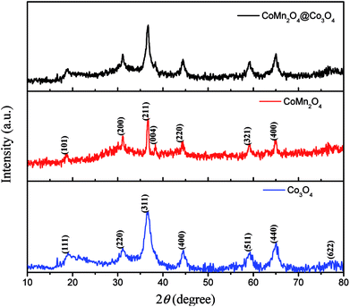
The XRD patterns of as-synthesized CoMn2O4, Co3O4 and CoMn2O4@Co3O4 exfoliated from Ni foam are shown in Fig. 1. The patterns of as-synthesized samples could be indexed to the CoMn2O4 (JCPDS Card no. 77-0471)24 and Co3O4 (JCPDS Card no.42-1467).25 Besides, from the pattern of CoMn2O4@Co3O4, CoMn2O4 and Co3O4 diffraction peaks overlap together and broad peaks were recognized, indicating the combination of the crystalline CoMn2O4 and Co3O4 in one nanostructure. Energy Dispersive Spectrometer (EDS) analysis datum, SEM-mapping pictures and STEM mapping images shown in Fig. S1† is consistent with the XRD result. It shows that as-synthesized CoMn2O4@Co3O4 is mainly composed of Co, O, and Mn chemical elements.The structure and morphology of the as-prepared samples were characterized by FESEM and TEM. Fig. 2(a–c) present the typical FESEM images of the CoMn2O4 nanoneedles arrays supported on Ni foam. On the observation of high-magnification image (Fig. 2(c)), we found that the obtained CoMn2O4 nanoneedles arrays (with lengths of ∼1μm and diameters of ∼20–70 nm) are highly densely. Fig. 2(d–f) show FESEM images of the as-synthesized large-scale and dense Co3O4 nanosheets. It can be observed that the Co3O4 nanosheets exhibits interconnected big channels. Fig. 2(g–i) represent the FESEM images of the CoMn2O4@Co3O4 core–shell hybrid nanostructure arrays grown on Ni foam. The CoMn2O4 nanoneedles are uniformly enwrapped in the Co3O4 nanosheets. The CoMn2O4 nanoneedles clusters were almost all covered by Co3O4 nanosheets with an overall size of ∼15 μm. The TEM images in Fig. 2(j–l) also further reveal the hybrid nanostructure of an individual CoMn2O4@Co3O4 core/shell nanowire, although hierarchical nanoflower structure cannot be clearly observed, probably owing to the partial damage from TEM sample preparation procedure (sonication). The HRTEM image of CoMn2O4@Co3O4 further verifies the crystal structure. Fig. 2(l) and S2† reveal a distinct set of visible lattice fringes with interplanar spacings of 0.240 nm, 0.453 nm, 0.291 nm, 0.243 nm and 0.204 nm, which correspond to the (211) plane of CoMn2O4, (111) plane of Co3O4, (220) plane of Co3O4, (311) plane of Co3O4, and (400) plane of Co3O4, respectively. The results are consistent with the XRD results patterns. The N2-adsorption/desorption measurements were carried out to study the surface area and porosity property of the samples. BET analysis results show that the specific surface area of CoMn2O4@Co3O4 core/shell nanoflowers is 67.5 m2 g−1, which is much higher than that of CoMn2O4 nanoneedles (44.3 m2 g−1) and Co3O4 nanoflowers (61.2 m2 g−1) (Fig. S3†). The pore size distributions of these samples are shown in the insets, confirming that the samples have mesoporous characteristics. Obviously, the CoMn2O4@Co3O4 core/shell configuration can provide a higher surface area, which is mainly attributed to the interconnected Co3O4 nanosheets and the aligned CoMn2O4 nanoneedles scaffold that creating a 3D interconnected porous network and highly porous surface morphology. Such interconnected network configuration not only provides large surface area for charge storage but also facilitates electrolyte penetration through the mesopores and increase the utilization of the active materials.26–29 Based on the above mentioned merits, the CoMn2O4@Co3O4 core/shell nanoflowers can be employed as excellent electrode material for SCs and the detailed electrochemical measurements are performed as follows.
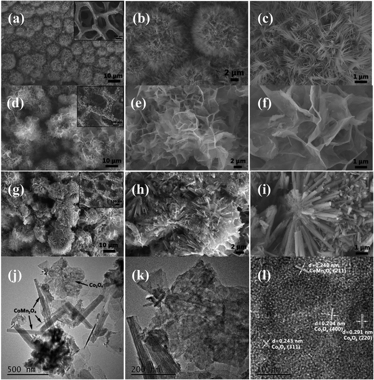 | ||
| Fig. 2 (a–c) SEM images of CoMn2O4 nanoneedles arrays. (d–f) SEM images of Co3O4 nanoflowers. (g–i) CoMn2O4@Co3O4 core/shell nanoflower arrays. (j–l) TEM image of CoMn2O4@Co3O4. | ||
3.2. Electrochemical performance of CoMn2O4@Co3O4 core/shell electrodes
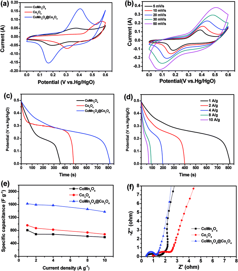
Fig. 3(a) shows the CV curves of CoMn2O4, Co3O4 and CoMn2O4@Co3O4 core/shell electrodes between a potential window of 0 and 0.6 V at a scan rate of 10 mV s−1. Clearly, the CV integrated area of the CoMn2O4@Co3O4 electrode was significantly larger compared with the unitary electrodes, indicating that the CoMn2O4@Co3O4 core/shell electrodes have a apparently larger specific capacitance than pure CoMn2O4 or Co3O4 electrode.The redox reaction mechanism for CoMn2O4 is represented by the following equations:30–33
| CoMn2O4 + H2O + OH− → CoOOH + 2MnOOH + e− | (4) |
| MnOOH + OH− → MnO2 + H2O + e− | (5) |
As shown, two pairs of redox peaks for the Co3O4 electrode appear in the CVs, which is due to the Co2+/Co3+ and Co3+/Co4+ reactions, described by the following reaction:30,34
| (+)3Co(OH)2 + OH− → Co3O4 + 4H2O + e− | (6) |
| Co3O4 + OH− + H2O → 3CoOOH + e− | (7) |
| CoOOH + OH− → CoO2 + H2O + e− | (8) |
| 4OH− → O2 + 2H2O + 4e− | (9) |
| (−)CoO2 + H2O + e− → CoOOH + OH− | (10) |
| 3CoOOH + e− → Co3O4 + OH− + H2O | (11) |
| Co3O4 + H2O + 2e− → 3Co(OH)2 + 2OH− | (12) |
A pair of significantly enhanced redox peaks can be observed at the voltage of 0.16 V and 0.41 V for the CoMn2O4@Co3O4 electrode, which may originate from the fast faradaic redox reactions and the short ion diffusion path provided by CoMn2O4 and Co3O4, as shown in reaction (4)–(12).
Fig. 3(b) shows the CV curves of the CoMn2O4@Co3O4 electrode at various scan rates. As the sweep rate increases, the cathodic peak position was shifted from 0.18 to 0.07 V and the anode peak position was shifted from 0.38 to 0.51 V, which is due to the polarization effect of the electrode.
The improved capacitive performance was also evaluated by galvanostatic charge–discharge (GCD) measurements over a potential range from 0 to 0.5 V. Fig. 3(c) presents the comparison of the discharge curves at 1 A g−1 for CoMn2O4, Co3O4, and CoMn2O4@Co3O4 electrodes. As expected, the CoMn2O4@Co3O4 electrode demonstrate a much longer discharging time than the CoMn2O4 and Co3O4 electrodes, indicating its higher capacitance. In addition, the discharge curves of the CoMn2O4@Co3O4 electrode and specific capacitance of the samples from 1 to 10 A g−1 are shown in Fig. 3(d) and (e), respectively. Based on the GCD curves, the capacitances of CoMn2O4@Co3O4 electrode are calculated to be 1627, 1593, 1575, 1459 and 1376 F g−1 at 1, 2, 4, 8 and 10 A g−1, respectively, which are much higher than the pure CoMn2O4 electrode with the value of 808, 686, 684, 621 and 593 F g−1 and bare Co3O4 electrode with the value of 959, 871, 824, 738 and 682 F g−1 at the same discharge current densities. The significant performance increment of the CoMn2O4@Co3O4 hybrid electrode was also confirmed by electrochemical impedance spectroscopy (EIS). The impedance spectra were obtained using an AC voltage of 5 mV in a frequency range from 0.01 Hz to 100 kHz. The electrochemical impedance data were analyzed with a Randles equivalent circuit that includes the charge transfer resistance (Rct), and the straight line in the low-frequency region represents the diffusive resistance (W). In addition, the internal resistance (Re) is obtained from the high-frequency intersection of the Nyquist plot in the real axis.35 There are a single semicircle in the high-frequency region and a straight line in the low-frequency region in the Nyquist plots of the three electrodes (Fig. 3(f)). The semicircle at high frequency region corresponds to the charge transfer processes whereas the straight line at low-frequency region relates to the ion diffusion processes.36 The smaller semicircle diameter (lower Rct) indicates faster electron-transfer kinetics of corresponding electrode.37–39 CoMn2O4@Co3O4 electrode exhibits a smaller radius in the high-frequency region and a steeper line in the low-frequency region than those of other two electrodes, indicating superior charge transfer and ion diffusion kinetics behavior.
Cycling stability is another important parameter for high-performance supercapacitors. The long-term cycling stability of as-synthesized supercapacitors was tested through a repetitive galvanostatic charge/discharge process at a constant current density of 4 A g−1 for 3000 cycles (Fig. 4). It can be observed that the specific capacitance of CoMn2O4@Co3O4 electrode firstly increases before 200 cycles, and then decreases with cycle number increasing, suggesting an activation process occurring during the beginning of a successive scan.40 It is important to indicate that the electrode shows capacitance retention of 87.6% after 3000 cycles. The decrease of the specific capacitance could be attributed to the dissolution of the outer Co3O4 in alkaline electrolyte, leading to loss of active materials. The excellent stability may be mainly attributed to the unique hierarchical porous core/shell morphology of the CoMn2O4@Co3O4 hybrid. The CoMn2O4 nanowire arrays on the Ni foam serve as a supporting framework for the ultrathin and interconnected Co3O4 nanosheets to produce an hierarchical nanostructures array and therefore enhance the mechanical stability.
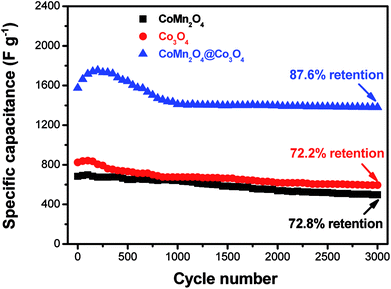 | ||
| Fig. 4 Cycling performances of CoMn2O4, Co3O4 and CoMn2O4@Co3O4 electrodes at a current density of 4 A g−1. | ||
In conclusion, the outstanding electrochemical performance of the CoMn2O4@Co3O4 hybrid electrode can be mainly ascribed to the unique core–shell hierarchical porous nanostructure, providing the advantages as follows: (i) both CoMn2O4 and Co3O4 are good pseudo-capacitive materials in KOH electrolyte, hence contributing to the enhanced pseudo-capacitance activity. (ii) The unique hierarchical core/shell porous nanostructure is anticipated to enhance the amount of accessible active sites for the capacitive reactions,41 and can supply a short and fast ion diffusion pathway, thus enhancing the faradic reaction.
3.3. Electrochemical characterization of CoMn2O4@Co3O4//AC ASC
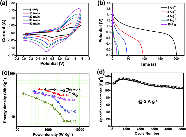
As shown in Fig. 5(a), the CV curve of AC electrode from −1.0 to 0 V (vs. Hg/HgO) exhibits a nearly rectangular shape, typical of capacitive behavior, which indicates the characteristic of the electric double layer capacitance, while that of CoMn2O4@Co3O4 within a voltage the potential window of 0 to 0.6 V (vs. Hg/HgO). As shown in Fig. 6(a), the CoMn2O4@Co3O4//AC device showed a nearly ideal capacitive behavior with a cell voltage up to 1.6 V at a scan rate of 50 mV s−1. The achieved high operating voltage of the device benefits from the advantage of the different stable potential windows of CoMn2O4@Co3O4 and AC electrodes.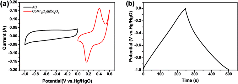 | ||
| Fig. 5 (a) CV curves of the CoMn2O4@Co3O4 and AC electrodes at a scan rate of 10 mV s−1. (b) Galvanostatic charge–discharge curve of the AC electrode at a current density of 1 A g−1. | ||
To obtain the maximum performance of the CoMn2O4@Co3O4//AC ASC, it is crucial to keep the charges balanceable with the relationship q+ = q−. In order to get the charge balanceable, the optimum loading mass of AC was decided by the following equation:
| m(CoMn2O4@Co3O4)/m(AC) = Cm(AC)ΔV(AC)/Cm(CoMn2O4@Co3O4)ΔV(CoMn2O4@Co3O4) | (13) |
Fig. 6(a) shows the CV curves of the CoMn2O4@Co3O4//AC ASC at various scan rates. The CoMn2O4@Co3O4//AC ASC exhibits an irregular shape CV curve, which is distinct from the CV curve of the AC electrode with a rectangular shape. The distortion of CV curves from rectangular-like shapes may be attributed to the pseudo-capacitance from CoMn2O4@Co3O4//AC cathode.42,43 The discharge curves of the ASC device at various current densities within the potential window of 0–1.6 V are shown in Fig. 6(b). The specific capacitances of CoMn2O4@Co3O4//AC ASC were calculated according to the eqn (1) to be 125.8, 120.6, 114.7, 97.1 and 87.4 F g−1 at the current densities of 1, 2,4, 8, 10 A g−1, respectively. It is worth noting that even at a high current density of 10 A g−1, the specific capacitance still reaches up to 87.4 F g−1 (about 69.5% of the capacitance retained), indicating its good rate capability. Note that the specific capacitance is about six times larger than that of conventional AC-based symmetric capacitors (∼20 F g−1),44 which is enhanced by the ultra-high pseudo-capacitance of the CoMn2O4@Co3O4 electrode. To examine the supercapacitor performance of the CoMn2O4@Co3O4//AC device, the energy density (E) and power density (P) of the ASC were calculated according to the eqn (2) and (3), and corresponding Ragone plot is in Fig. 6(c). The CoMn2O4@Co3O4//AC supercapacitor could achieve a high E value of 44.8 W h kg−1 (with a P value of 800.5 W kg−1) and still maintain 31.1 W h kg−1 at a high power density of 8010.3 W kg−1. Note that the energy and power densities of the present ASC are superior to that of many ASCs using core–shell nanostructure materials as electrode positive electrode, such as MnMoO4·H2O@MnO2//AC,45 Co3O4@Ni(OH)2//AC,46 NiCo2S4@Co(OH)2//AC47 and NiCo2O4@MnO2//AC.48 We believe that the high energy and power density of our ASC are mainly due to the wide working voltage window and the improved specific capacitance comes from the high synergistic effect of these two electrodes.
The long-term cycling stability of the CoMn2O4@Co3O4//AC ASC was examined by successive galvanostatic charge–discharge cycling at a current density of 2 A g−1 for 5000 cycles. As shown in Fig. 6(d), the ASC shows capacitance retention of 89.2% after 5000 cycles. Note that the rate capability and cycling stability of the CoMn2O4@Co3O4//AC ASC is comparable or superior to many state-of-art ASC systems (Table S2†), further indicating the advantage of the CoMn2O4@Co3O4//AC ASC. The high power density with energy density, excellent rate capability and cycling stability make the CoMn2O4@Co3O4//AC ASC as a promising candidate for practical energy storage.
4. Conclusions
We have successfully prepared hierarchical CoMn2O4@Co3O4 core/shell nanowire arrays with attractive pseudocapacitance behaviors in situ grown on Ni foam by simple, cost-effective, and facile hydrothermal method. The resultant CoMn2O4@Co3O4 core/shell nanowire arrays exhibited significant capacitance, as compared with bare CoMn2O4 and Co3O4. The CoMn2O4@Co3O4 hybrid with unique architecture is then used as binder-free electrode for supercapacitors. This electrode exhibits a high specific capacitance of 1627 F g−1 at 1 A g−1 and 1376 F g−1 at 10 A g−1. An ASC device employing the CoMn2O4@Co3O4 electrode and active carbon electrode delivers a high specific energy of 125.8 F g−1 at 1 A g−1 as well as high energy density of 44.8 W h kg−1. Also, the ASC exhibits high cycling stability with capacitance retention of 89.2% after 5000 charge/discharge cycles at a current density of 2 A g−1. The superior electrochemical performance indicate that the present low-cost CoMn2O4@Co3O4 core/shell hybrid can serve as a promising electrode material for high-performance supercapacitors.Conflicts of interest
The authors declare no conflict of interest.Acknowledgements
This work was supported by the National Natural Science Foundation of China (Grant No. 11747001), the Scientific Research Fund of Jiangsu Provincial Education Department (Grant No. 17KJB140029), the Key Applied Basic Research Program of Yunnan Province (Grant No. 2017FA024) and Program for Innovative Research Team (in Science and Technology) in University of Yunnan Province.References
- A. Burke, J. Power Sources, 2000, 91, 37–50 CrossRef.
- S. Chu and A. Majumdar, Nature, 2012, 488, 294 CrossRef PubMed.
- J. R. Miller and P. Simon, Science, 2008, 321, 651–652 CrossRef PubMed.
- H. Wang, H. S. Casalongue, Y. Liang and H. Dai, J. Am. Chem. Soc., 2010, 132, 7472–7477 CrossRef PubMed.
- C. Liu, F. Li, L. P. Ma and H. M. Cheng, Adv. Mater., 2010, 22, E28–E62 CrossRef PubMed.
- B. Wang, T. Zhu, H. B. Wu, R. Xu, J. S. Chen and X. W. Lou, Nanoscale, 2012, 4, 2145–2149 RSC.
- X. H. Xia, J. P. Tu, Y. Q. Zhang, Y. J. Mai, X. L. Wang, C. D. Gu and X. B. Zhao, J. Phys. Chem. C, 2011, 115, 22662–22668 CrossRef.
- X. Yu, B. Lu and Z. Xu, Adv. Mater., 2014, 26, 1044–1051 CrossRef PubMed.
- X. L. Guo, M. Kuang, F. Dong and Y. X. Zhang, Ceram. Int., 2016, 42, 7787–7792 CrossRef.
- X. Wang, H. Xia, J. Gao, B. Shi, Y. Fang and M. Shao, J. Mater. Chem. A, 2016, 4, 18181–18187 RSC.
- L. G. Xiao, L. Gang, K. Min, Y. Liang and X. Z. Yu, Electrochim. Acta, 2015, 174, 87–92 CrossRef.
- X. L. Guo, M. Kuang, F. Li, X. Y. Liu, Y. X. Zhang, F. Dong and D. Losic, Electrochim. Acta, 2016, 190, 159–167 CrossRef.
- P. Ahuja, V. Sahu, S. K. Ujjain, R. K. Sharma and G. Singh, Electrochim. Acta, 2014, 146, 429–436 CrossRef.
- S. Jiang, T. Shi, H. Long, Y. Sun, W. Zhou and Z. Tang, Nanoscale Res. Lett., 2014, 9, 492 CrossRef PubMed.
- L. Ren, J. Chen, X. Wang, M. Zhi, J. Wu and X. Zhang, RSC Adv., 2015, 5, 30963–30969 RSC.
- X. L. Guo, X. Y. Liu, X. D. Hao, S. J. Zhu, F. Dong, Z. Q. Wen and Y. X. Zhang, Electrochim. Acta, 2016, 194, 179–186 CrossRef.
- X. L. Guo, J. M. Zhang, W. N. Xu, C. G. Hu, L. Sun and Y. X. Zhang, J. Mater. Chem. A, 2017, 5, 20579–20587 RSC.
- X. Wang, B. Shi, X. Wang, J. Gao, C. Zhang, Z. Yang and H. Xie, J. Mater. Chem. A, 2017, 5, 23543–23549 RSC.
- H. Jiang, C. Li, T. Sun and J. Ma, Chem. Commun., 2012, 48, 2606–2608 RSC.
- X. Wang, B. Shi, Y. Fang, F. Rong, F. Huang, R. Que and M. Shao, J. Mater. Chem. A, 2017, 5, 7165–7172 RSC.
- X. Liu, S. Shi, Q. Xiong, L. Li, Y. Zhang, H. Tang, C. Gu, X. Wang and J. Tu, ACS Appl. Mater. Interfaces, 2013, 5, 8790–8795 CrossRef PubMed.
- D. Cai, D. Wang, B. Liu, L. Wang, Y. Liu, H. Li, Y. Wang, Q. Li and T. Wang, ACS Appl. Mater. Interfaces, 2014, 6, 5050–5055 CrossRef PubMed.
- J. Liu, J. Jiang, C. Cheng, H. Li, J. Zhang, H. Gong and H. J. Fan, Adv. Mater., 2011, 23, 2076–2081 CrossRef PubMed.
- K. N. Jung, S. M. Hwang, M. S. Park, K. J. Kim, J. G. Kim, S. X. Dou, J. H. Kim and J. W. Lee, Sci. Rep., 2015, 5, 7665 CrossRef PubMed.
- X. Liu, Q. Long, C. Jiang, B. Zhan, C. Li, S. Liu, Q. Zhao, W. Huang and X. Dong, Nanoscale, 2013, 5, 6525–6529 RSC.
- T. Zhu, J. S. Chen and X. W. Lou, J. Mater. Chem., 2010, 20, 7015–7020 RSC.
- B. L. Ellis, P. Knauth and T. Djenizian, Adv. Mater., 2014, 26, 3368–3397 CrossRef PubMed.
- Y. Gao, L. Mi, W. Wei, S. Cui, Z. Zheng, H. Hou and W. Chen, ACS Appl. Mater. Interfaces, 2015, 7, 4311–4319 CrossRef PubMed.
- X. Chen, J. Ding, J. Jiang, G. Zhuang, Z. Zhang and P. Yang, RSC Adv., 2018, 8, 29488–29494 RSC.
- X. Xia, J. Tu, Y. Zhang, X. Wang, C. Gu, X. B. Zhao and H. J. Fan, ACS Nano, 2012, 6, 5531–5538 CrossRef PubMed.
- J. Gomez and E. E. Kalu, J. Power Sources, 2013, 230, 218–224 CrossRef.
- L. Li, Y. Q. Zhang, X. Y. Liu, S. J. Shi, X. Y. Zhao, H. Zhang, X. Ge, G. F. Cai, C. D. Gu, X. L. Wang and J. P. Tu, Electrochim. Acta, 2014, 116, 467–474 CrossRef.
- L. Q. Mai, F. Yang, Y. L. Zhao, X. Xu, L. Xu and Y. Z. Luo, Nat. Commun., 2011, 2, 381 CrossRef PubMed.
- X. Xia, J. Tu, Y. Mai, X. Wang, C. Gu and X. Zhao, J. Mater. Chem., 2011, 21, 9319–9325 RSC.
- J. Wang, S. Wang, Z. Huang and Y. Yu, J. Mater. Chem. A, 2014, 2, 17595–17601 RSC.
- L. Zhang, Q. Ding, Y. Huang, H. Gu, Y. E. Miao and T. Liu, ACS Appl. Mater. Interfaces, 2015, 7, 22669 CrossRef PubMed.
- G. Nie, X. Lu, M. Chi, Y. Zhu, Z. Yang, N. Song and C. Wang, Electrochim. Acta, 2017, 231, 36–43 CrossRef.
- Z. Li, M. Shao, L. Zhou, R. Zhang, C. Zhang, J. Han, M. Wei, D. G. Evans and X. Duan, Nano Energy, 2016, 20, 294–304 CrossRef.
- G. X. Pan, X. H. Xia, F. Cao, J. Chen, P. S. Tang, Y. J. Zhang and H. F. Chen, Electrochim. Acta, 2014, 133, 522–528 CrossRef.
- Z. Xin, X. Yan, Y. Sun, Z. Bai, G. Zhang, Y. Shen, Q. Liang and Y. Zhang, ACS Appl. Mater. Interfaces, 2015, 7, 2480–2485 CrossRef PubMed.
- H. Wei, J. Wang, L. Niu, J. Sun, P. Gong and S. Yang, J. Alloys Compd., 2014, 608, 297–303 CrossRef.
- R. R. Salunkhe, J. Tang, Y. Kamachi, T. Nakato, J. H. Kim and Y. Yamauchi, ACS Nano, 2015, 9, 6288–6296 CrossRef PubMed.
- C. Guan, X. Qian, X. Wang, Y. Cao, Q. Zhang, A. Li and J. Wang, Nanotechnology, 2015, 26, 094001 CrossRef PubMed.
- Y. G. Guo, J. S. Hu and L. J. Wan, Adv. Mater., 2008, 20, 2878–2887 CrossRef.
- J. Xu, Y. Sun, M. Lu, L. Wang, J. Zhang, J. Qian and X. Liu, Chem. Eng. J., 2018, 334, 1466–1476 CrossRef.
- X. Bai, Q. Liu, J. Liu, H. Zhang, Z. Li, X. Jing, P. Liu, J. Wang and R. Li, Chem. Eng. J., 2017, 315, 35–45 CrossRef.
- R. Li, S. Wang, Z. Huang, F. Lu and T. He, J. Power Sources, 2016, 312, 156–164 CrossRef.
- K. Xu, W. Li, Q. Liu, B. Li, X. Liu, L. An, Z. Chen, R. Zou and J. Hu, J. Mater. Chem. A, 2014, 2, 4795–4802 RSC.
Footnote |
| † Electronic supplementary information (ESI) available. See DOI: 10.1039/c8ra06289g |
| This journal is © The Royal Society of Chemistry 2018 |

