
 Open Access Article
 This Open Access Article is licensed under a Creative Commons Attribution-Non Commercial 3.0 Unported Licence
Oxide removal and stabilization of bismuth thin films through chemically bound thiol layers†
Giuseppe Alessio Verni abc,
Brenda Long*abc,
Farzan Gityb,
Martin Laniusd,
Peter Schüffelgend,
Gregor Musslerd,
Detlev Grützmacherd,
Jim Greerbe and
Justin D. Holmesabc
abc,
Brenda Long*abc,
Farzan Gityb,
Martin Laniusd,
Peter Schüffelgend,
Gregor Musslerd,
Detlev Grützmacherd,
Jim Greerbe and
Justin D. Holmesabc
aSchool of Chemistry, University College Cork, Cork, T12 P2FY, Ireland. E-mail: brenda.long@ucc.ie
bTyndall National Institute, University College Cork, Cork, T12 PX46, Ireland
cAMBER@CRANN, Trinity College Dublin, Dublin 2, Ireland
dPeter Grünberg Institute 9, Jülich Aachen Research Alliance (JARA-FIT), Research Center Jülich, Germany
eFaculty of Science and Engineering, University of Nottingham Ningbo China, Ningbo, China
First published on 27th September 2018
Abstract
Bismuth has been identified as a material of interest for electronic applications due to its extremely high electron mobility and quantum confinement effects observed at nanoscale dimensions. However, it is also the case that Bi nanostructures are readily oxidised in ambient air, necessitating additional capping steps to prevent surface re-oxidation, thus limiting the processing potential of this material. This article describes an oxide removal and surface stabilization method performed on molecular beam epitaxy (MBE) grown bismuth thin-films using ambient air wet-chemistry. Alkanethiol molecules were used to dissolve the readily formed bismuth oxides through a catalytic reaction; the bare surface was then reacted with the free thiols to form an organic layer which showed resistance to complete reoxidation for up to 10 days.
Bulk bismuth has been identified as a material of interest for electronic applications, due to its extremely high electron mobility (>104 cm2 V−1 s at 300 K).1 The lower Fermi velocity of the surface states of Bi (111) and (110), coupled with larger Fermi surface elements compared to the bulk, leads to a density of states at the Fermi level that is higher at the surface, such that the surface can be considered to be a pseudo-2 D material under certain orientations.2,3 Bi nanowires have previously been investigated for their thermoelectric properties due to their small electron effective mass and highly anisotropic Fermi surface.4
Thickness and crystallographic orientation are key parameters that determine the electronic structure of Bi thin films, the first as it affects the quantum confinement of the material5 and the second because of the strong electronic anisotropy6 of Bi. The relatively large Fermi wavelength of Bi (approximately 40 nm (ref. 7)) can potentially lead to quantum confinement effects at nanoscale dimensions, e.g. semimetal-to-semiconductor transitions have been both predicted5 and observed8 in Bi nanostructures. This semimetal-to-semiconductor transition in Bi has been utilised to form a semiconducting channel between semi-metallic source and drain regions, in what is defined as a confinement modulated gap transistor (CMGT).9 This is a dopant-free transistor that does not suffer from dopant fluctuation and activation problems. Recently a hetero-dimensional rectifier was formed on bismuth thin-films and consisted of a 3D semi-metallic region next to a thin 2D semiconducting region.10 Rectifying behaviour was observed in the Bi diode at room temperature, highlighting that a ‘junction’ can be created without dopant atoms.
However, the fabrication of the Bi CMGTs relies on the formation of the metal-semimetal junction in a UHV system in order to prevent surface re-oxidation, as the surface has been shown to readily re-oxidise when in contact with air, leading to a decrease in resistance.8 While UHV oxide removal through RIE is a simple process, it does not allow for surface passivation and subsequent ambient air handling, requiring an additional capping step to prevent re-oxidation of the device.
The oxidation of bismuth thin films was first reported by Hapase et al.11 in 1967, who found that oxidation proceeds by diffusion of the Bi from the thin film through the oxide film, as previously hypothesised,12 via a Wagner mechanism. Further studies then correlated the oxide thickness to a diffusion equation and showed that a metastable crystal phase of the oxide is present which evolves into a different stable phase upon heating applied.13 In 1990 Puckrin et al.14 compared the oxidation of bulk bismuth and thin films using different spectroscopy techniques and showed that, in both cases, BiO is the first oxide formed on the surface of the samples with a total thickness of approximately 8 monolayers (ca. 2 nm). Further results showed that prolonged air oxidation times lead to further oxidation of the film and to the formation of Bi2O3, which ties back with the results described previously by Kowalczyk et al.15 Despite these reports, the oxidation behavior of Bi thin films has not been studied extensively.
Self-assembled monolayers (SAMs) formed by chemisorption of alkyl thiols on the surface of various inorganic substrates have been extensively reported in the literature; in particular, their use as corrosion inhibitors has been explored on various semiconductors16–19 and metals.20,21 There are two examples of alkyl thiol adsorption on bulk Bi electrode surfaces; Adamovski et al.22 reported the characterization of alkyl thiol adsorption thickness via the diffusion blocking properties of the layer, whilst Romann et al.23 characterized the formation of bismuth thiolate at the surface of the electrode in the absence of a self-assembled monolayer.
This article reports the first example of SAM formation on Bi thin films via a wet chemical process (Scheme 1). The SAM surfaces have been characterised via XPS, IR and AFM and show that, in a similar fashion as for Cu surfaces,21 the alkyl thiol plays an active role in removing the native bismuth oxide from the thin film surface and leads to subsequent stabilization of Bi surfaces preventing complete re-oxidation. Whilst complete oxide removal was not achieved for the films, likely due to a non-continuous passivating layer, the research highlights the ability to remove oxide and passivate Bi surfaces outside of a vacuum environment.
 | ||
| Scheme 1 Depiction of the procedure for the removal of bismuth oxide and its subsequent passivation with thiols. | ||
Bi films used in this study (supplied by the research centre, Jülich, in Germany) were grown by molecular beam epitaxy (MBE) on undoped Si [111] substrates. Prior to bismuth deposition, the Si substrates were chemically cleaned by the HF-last RCA24 procedure to remove the native oxide and to passivate the surface with hydrogen. The substrates were subsequently heated in situ to 700 °C for 20 min to desorb the hydrogen atoms from the Si surface. The Bi material flux was generated by an effusion cell operated at a temperature of 550 °C, which yields a growth rate of 17 nm h−1.8
A round bottom flask was preheated using a heating mantle up to 180 °C and left at this temperature for 30 min. The Bi thin films were then placed in the flask under N2, annealed for 1 h and left to cool to room temperature. Solutions of 1-dodecanethiol (Sigma-Aldrich, ≥98%) in isopropanol (IPA) were prepared, with concentrations ranging from 1 to 100 mM. The solutions were degassed using three freeze–pump–thaw cycles and transferred in the sample flask using a cannula, thus preventing any contact with the outer atmosphere.
The Bi samples were left immersed in solution at room temperature overnight after which time the solution was vacuum pumped out of the flask using a cannula. The samples were then dried by gently heating the flask using a heat gun in order to evaporate the remaining solvent. Clean IPA was pumped into the sample flask to rinse any adsorbed molecules. IPA was then removed, and the thin film dried once again. The same reaction procedure was also used on Bi powder (Fisher Scientific, 100 mesh, 99.5% metal basis) which was used as received. The samples were then transferred to a N2 glovebox from the flask to a gel box which was subsequently transferred to a N2 filled sample preserver. The gel box was kept in the sample preserver until X-ray photoelectron spectroscopy (XPS) measurements were carried out. The exposure time during the loading procedure into the XPS entry chamber was less than 30 s. The XPS powder samples were prepared by depositing the reacted powder on some carbon tape. The powder was degassed overnight in the XPS entry chamber before being analyzed. The exposure time to air of these samples was less than 1 h. XPS data were collected using an Oxford Applied Research Escabase® XPS system. Survey scans were recorded between 0–1400 eV with a step size of 0.7 eV, dwell time of 0.5 s and pass energy of 100 eV. Core level scans were acquired with a step size of 0.1 eV, dwell time of 0.5 s and pass energy of 20 eV averaged over 20 scans. A non-monochromated Al-kα X-ray source operating at 100 W power was used for all scans. All spectra were acquired at a take-off angle of 90° with respect to the analyser. Energy calibration for all spectra was obtained using the C 1s line at 284.8 eV as reference data was processed using CasaXPS software where a Shirley background correction was employed. Relative sensitivity factors used for quantification purposes are from the CasaXPS software library. XPS thickness measurements were performed following the methodology originally defined by Cumpson et al.,25 (see eqn (1)).
 | (1) |
1H (300 MHz) and 13C (75.5 MHz) Nuclear Magnetic Resonance (NMR) spectra were recorded on a Bruker Advance 300 MHz NMR spectrometer. All spectra were recorded at 300 K in deuterated chloroform (CDCl3) using tetramethylsilane (TMS) as an internal standard. Attenuated total reflectance infrared (ATR-FTIR) spectra were recorded using a Nicolet 6700 Infrared Spectrometer with a VariGATR and a liquid cooled MgCdTe detector using 3000 scans at a resolution of 2 cm−1. Spectra were collected under p-polarisation in an ambient atmosphere. Fig. 1 shows XPS scans of the Bi 4f core level peak for the thin films before and after reaction with different concentrations of thiol solutions. At 156.5 eV and 161.8 eV the Bi metal 4f components are present27 and at 158.6 eV and 163.4 eV Bi–X 4f components28 are present, where X is a heteroatom, in this case O. Treatment of the Bi films with a 1 mM 1-dodecanethiol solution did not reduce the intensity of the Bi–X peak considerably, as also shown in Table S1.† However, XPS analysis of Bi films treated with 10 and 100 mM thiol solutions displayed a high Bi metal content, when the Bi peaks at 156.5 eV and 161.8 eV are compared to those of the as received sample. The shoulder peaks at 158.6 eV and 163.4 eV, whilst usually associated with Bi2O3, in this case are likely to be composed of both Bi–O and by Bi–S components. This hypothesis is based on the analysis of the thickness of the thiol-coated Bi thin films by XPS following the method outlined in the experimental section. The thickness of the overlayer, calculated using the Bi–X shoulder as the overlayer peak and the Bi 4f7/2 peak as the thin film peak, was approximately 0.95 ± 0.10 nm. The thickness of the oxide calculated using the O 1s Bi2O3 component as the overlayer peak and the Bi 4d5/2 peak as the thin film peak was found to be 0.43 ± 0.05 nm. This discrepancy in thickness is likely due to S also bound to surface Bi atoms, thus leading to a Bi 4f shoulder peak that was more intense due to contributions from both components, i.e. Bi–S and Bi–O.
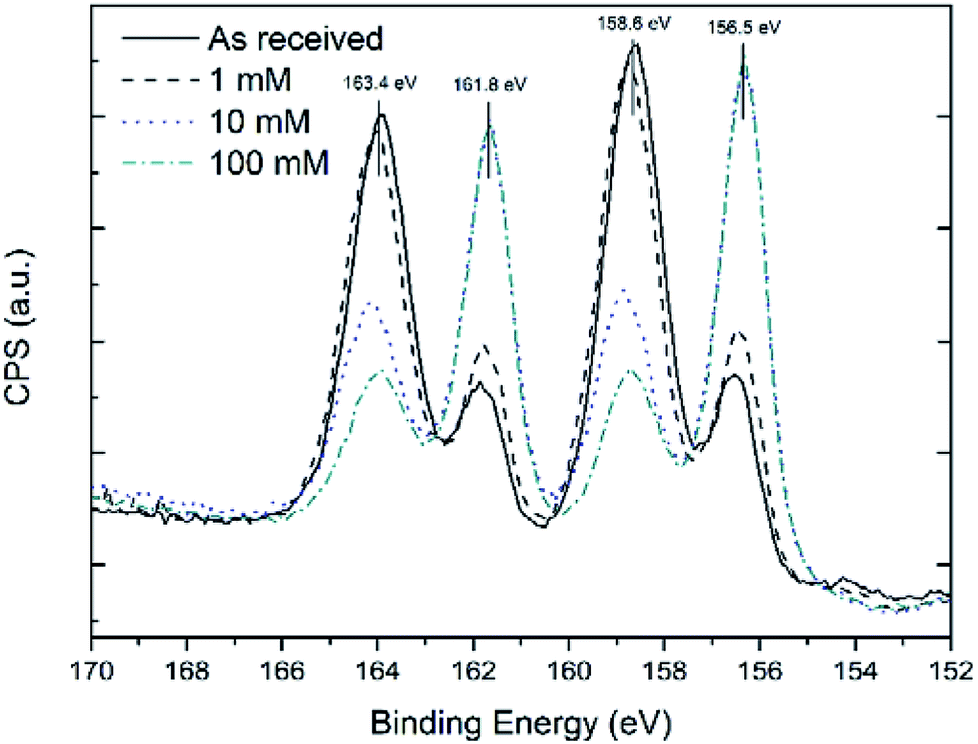 | ||
| Fig. 1 Overlaid XPS spectra of Bi 4f core level after reaction with 1-dodecanethiol solutions at different concentrations. Graphs have been normalised to the maximum of the as-received sample to underline the oxide reduction effect. | ||
Fig. 2 shows an ATR-FTIR scan of the Bi thin film surface before and after the functionalisation process. The solvent-cleaned as-received Bi thin films presents vibrations only due to adventitious carbon adsorbed on the surface. After functionalisation and air exposure, multiple vibrations were observed at 2993 and 2909 cm−1, arising from C–H stretches and vibrations from the aliphatic carbon chains of the thiol molecules. In the fingerprint region between 1500–750 cm−1 there are the two peaks associated with the asymmetric stretching of SO2 at 1367 cm−1 and 1174 cm−1 and one peak due to symmetric stretching at 1083 cm−1.29 This data suggests that the outer facing thiols from the second adsorbed layer, due to the oxidative environment created by the Bi2O3/Bi pair,30,31 are readily oxidised to their sulfonic acid equivalents. Surface bound thiols are known to progressively oxidise to sulfonic acids in the presence of strong oxidative environments.32,33
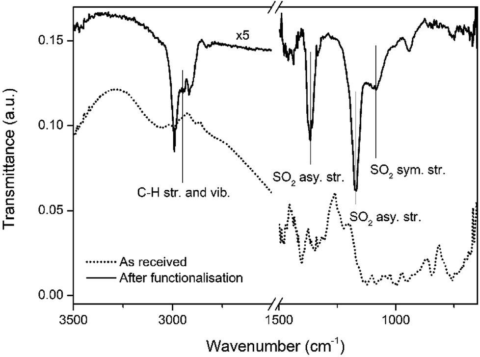 | ||
| Fig. 2 IR spectra of Bi surface before and after functionalisation. | ||
Bi(III) likely catalyses the formation of a disulphide bond between two 1-dodecanethiol molecules, similarly to what has already been observed for copper34 with water as a by-product.
As the sample/solution system is kept under N2, the oxide layer cannot form again and is consumed.30 Once the bare Bi surface is exposed, the thiol passivates the surface as the Bi–S bond is thermodynamically more favourable than the Bi–O bond.35,36 To confirm this mechanism, further experiments were undertaken on Bi powder. The powder samples, which presented a bismuth oxide![[thin space (1/6-em)]](https://www.rsc.org/images/entities/char_2009.gif) :bismuth ratio similar to that of the films (see Table S1†), were annealed at 180 °C for 1 h, under similar conditions to the Bi-coated Si substrates. The annealed powder samples were then immersed in 1-dodecanethiol solutions made in IPA and left in air in order to promote re-oxidation. After approximately 3 h, the solutions changed colour from colourless to yellow, and a precipitate was formed which was collected and dissolved in CDCl3 for NMR analysis (See Fig. S1†). NMR data for the as-received 1-dodecanethiol was also collected and used for comparison to check for the presence of starting material at the end of the reaction.
:bismuth ratio similar to that of the films (see Table S1†), were annealed at 180 °C for 1 h, under similar conditions to the Bi-coated Si substrates. The annealed powder samples were then immersed in 1-dodecanethiol solutions made in IPA and left in air in order to promote re-oxidation. After approximately 3 h, the solutions changed colour from colourless to yellow, and a precipitate was formed which was collected and dissolved in CDCl3 for NMR analysis (See Fig. S1†). NMR data for the as-received 1-dodecanethiol was also collected and used for comparison to check for the presence of starting material at the end of the reaction.
Fig. 3(a) shows an NMR spectrum for the as-received 1-dodecanethiol; a quartet resonating at 2.51 ppm (J = 7.33 Hz), arising from the α-methylene group of the thiol group was identified. The β-methylene and the thiol proton resonate at 1.60 ppm (quintet, J = 7.58 Hz) and 1.39 ppm (unresolved multiplet) respectively, the methyl of the C12 carbon is found at 0.87 ppm (triplet, J = 6.90 Hz) and the remaining protons on C3–C11 form an unresolved multiplet at 1.26 ppm.37 Fig. 3(b) shows an NMR spectrum of the reaction product formed upon reacting 1-dodecanethiol with Bi powder; two α-methylene groups from a disulphide moiety resonate as a triplet at 2.68 ppm (J = 7.35 Hz); two β-methylene groups resonate at 1.67 ppm (quintet, J = 7.31 Hz) and between 1.26 and 1.39 ppm there is an unresolved multiplet formed by the protons on the two alkyl chains. The remaining two methyl groups at the end of the chains resonate at 0.88 ppm (triplet, J = 6.70 Hz).38 No starting material was observed in the final NMR spectra, as the characteristic α-methylene quartet was not apparent. The reaction carried out with the Bi powder in air can proceed indefinitely until all the starting material is oxidized; the powder is in fact allowed to re-oxidize, unlike under N2, thus catalysing the reaction. No precipitate or change in colour of the solution was observed when thiol passivation was undertaken on Bi thin films left in air, probably due to the much smaller surface area of Bi on a compared to the powder form, limiting the oxidation of a noticeable quantity of thiols. This might also explain why at low thiol concentrations only a small reduction of oxide was observed, as most of the thiols in solution are probably oxidized while removing the outer oxide layer, leaving only few molecules available to passivate the Bi films. Using concentrations higher than 100 mM led to visible corrosion of the surface of the sample; therefore, the optimum level was found to be 10 mM as it gave the highest oxide reduction without affecting surface quality.
 | ||
| Fig. 3 NMR spectra of (a) the as-received 1-dodecanethiol used for the reaction and (b) the dodecyldisulfide product found after reacting 1-dodecanethiol solution with bismuth powder. | ||
Functionalised Bi thin film samples were then left in air and re-measured using XPS to check the extent of re-oxidation over time. Fig. 4(a) shows a comparison of the Bi 4f core level peaks of a 100 mM functionalised sample after 1 h, 2 days and 10 days of air exposure. The increase in intensity of the shoulder peaks at 159.3 eV and 164.6 eV arises from oxidation of exposed areas of the thin film, due to the non-continuity of the thiol film formed, as shown by AFM (see Fig. S2†). Fig. 4(b) shows the O 1s peak of thiol functionalised samples before and after air exposure. At 530.3 eV the Bi2O3 component increases in intensity after air exposure,39 further proof that part of the surface undergoes re-oxidation. This increase is accompanied by a general decrease in intensity in the two components at 532.6 eV (ref. 40 and 41) and 534.7 eV;42 likely belonging to O–H/S–O and H2O respectively. The hydroxyl arising from H-termination of the oxidised areas of the sample, the sulfoxide from likely oxidation of the outer facing thiol groups and the water from adsorption on the layer of the reaction by-product due to hydrophilicity of the outer facing thiol group.43,44 However, even after 10 days in air, there was no noticeable changes compared to a 1 h air exposure. Based on this data, an interdigitated “bilayer” of thiols is likely to be present; it has already previously been shown that these “bilayer” structures can be easily formed both on nanoparticles45,46 and on 2-D films47 when using a polar solvent. Moreover, a previous study on silver colloidal nanoparticles48 has shown that an excess of precursor molecules can lead to bilayer structures which in turn lead to an increase in the ambient stability. In a similar fashion, Cu functionalisation with excess thiols, leads to multilayer formation of self-assembled copper thiolate layers.34 This hypothesis is further corroborated by the thickness measurements which has quantified a total carbon layer thickness of 4.3 ± 0.5 nm, which equates to about 2.7 1-dodecanethiol monolayers. This configuration prevents further surface oxidation, thus allowing the bismuth to be more stable in air. In contrast, an unpassivated bismuth metal surface obtained by reactive ion etching (RIE), completely re-oxidizes in air after a 2 min exposure with oxidation levels comparable to the as received sample. Bi powder samples were also functionalized under N2 in a flask under similar conditions. The XPS analysis showed that the total content of oxide was reduced, although not to the same extent as for the thin film samples (see Fig. S3†); this is because of the higher oxide surface area of the powder, which in turn requires a higher number of thiol molecules to for oxide removal. In addition, as it was not possible to disperse the powder during the reaction, the thiol solution did not completely cover all the oxide surface available for the reaction.
 | ||
| Fig. 4 (a) XPS spectra of Bi 4f core level at different times after functionalisation. Graphs have been normalised to the maximum of the sample after reaction to outline the reoxidation process. (b) O 1s core level XPS spectra before and after reoxidation with main component peaks being highlighted. | ||
Conclusions
In conclusion, the data reported in this paper shows for the first time that oxide removal and stabilisation of nanoscale bismuth films is possible outside of a vacuum environment using a wet chemistry approach using the self-assembly of 1-dodecanethiol as a passivating agent. After 1 h there was some re-oxidation of the surface however after this point it was shown that the surface remained stable for up to 10 days, as opposed to 2 min for unpassivated surfaces. The mechanism of oxide removal took place through a bismuth oxide-catalysed thiol oxidation reaction, resulting in the exposure of bare Bi surfaces that were readily passivated by thiol molecules. While there is a basic understanding of the possible mechanisms behind the passivation reaction and oxidation resistance, there is still potential for improvement of the quality of the layer for example by employing different length thiol molecules as longer thiols have been shown to be more effective in lowering thin film re-oxidation rates.21 The easiness of the method and low cost of the precursors make it also potentially attractive for future large-scale production processes where scaling up will be required.Conflicts of interest
There are no conflicts to declare.References
- Y. Hasegawa, Y. Ishikawa, T. Saso, H. Shirai, H. Morita, T. Komine and H. Nakamura, Phys. Rev. B: Condens. Matter Mater. Phys., 2006, 382, 140–146 CrossRef CAS.
- C. R. Ast and H. Höchst, Phys. Rev. B: Condens. Matter Mater. Phys., 2003, 67, 1131021–1131024 CrossRef.
- P. Hofmann, Prog. Surf. Sci., 2006, 81, 191–245 CrossRef CAS.
- X. Sun, Z. Zhang and M. S. Dresselhaus, Appl. Phys. Lett., 1999, 74, 4005–4007 CrossRef CAS.
- Y. Lin, X. Sun and M. Dresselhaus, Phys. Rev. B: Condens. Matter Mater. Phys., 2000, 62, 4610–4623 CrossRef CAS.
- R. Hartman, Phys. Rev., 1969, 181, 1070–1086 CrossRef CAS.
- G. E. Smith, G. A. Baraff and J. M. Rowell, Phys. Rev., 1964, 135, A1118–A1124 CrossRef.
- F. Gity, L. Ansari, C. König, G. A. Verni, J. D. Holmes, B. Long, M. Lanius, P. Schüffelgen, G. Mussler, D. Grützmacher and J. C. Greer, Microelectron. Eng., 2018, 195, 21–25 CrossRef CAS.
- L. Ansari, G. Fagas, J. P. Colinge and J. C. Greer, Nano Lett., 2012, 12, 2222–2227 CrossRef CAS PubMed.
- F. Gity, L. Ansari, M. Lanius, P. Schüffelgen, G. Mussler, D. Grützmacher and J. C. Greer, Appl. Phys. Lett., 2017, 110, 093111 CrossRef.
- M. G. Hapase, V. B. Tare and A. B. Biswas, Acta Metall., 1967, 15, 131–133 CrossRef CAS.
- G. D. Palkar, D. N. Sitharamarao and A. K. Dasgupta, Trans. Faraday Soc., 1963, 59, 2634–2638 RSC.
- K. Komorita, M. Nisio and T. Nishinaga, Shinku, 1978, 21, 196–202 CrossRef CAS.
- E. Puckrin and A. J. Slavin, Phys. Rev. B: Condens. Matter Mater. Phys., 1990, 42, 1168–1176 CrossRef CAS.
- P. J. Kowalczyk, D. Belic, O. Mahapatra, S. A. Brown, E. S. Kadantsev, T. K. Woo, B. Ingham and W. Kozlowski, Appl. Phys. Lett., 2012, 100, 151904 CrossRef.
- P. Ardalan, C. B. Musgrave and S. F. Bent, Langmuir, 2009, 25, 2013–2025 CrossRef CAS PubMed.
- Q. Cai, B. Xu, L. Ye, Z. Di, S. Huang, X. Du, J. Zhang, Q. Jin and J. Zhao, Appl. Surf. Sci., 2015, 353, 890–901 CrossRef CAS.
- G. Collins, P. Fleming, S. Barth, C. O'Dwyer, J. J. Boland, M. A. Morris and J. D. Holmes, Chem. Mater., 2010, 22, 6370–6377 CrossRef CAS.
- P. W. Loscutoff and S. F. Bent, Annu. Rev. Phys. Chem., 2006, 57, 467–495 CrossRef CAS PubMed.
- T. Bürgi, Nanoscale, 2015, 7, 15553–15567 RSC.
- G. K. Jennings, J. C. Munro, T. H. Yong and P. E. Laibinis, Langmuir, 1998, 14, 6130–6139 CrossRef CAS.
- M. Adamovski, A. Zajac, P. Gründler and G. U. Flechsig, Electrochem. Commun., 2006, 8, 932–936 CrossRef CAS.
- T. Romann, V. Grozovski and E. Lust, Electrochem. Commun., 2007, 9, 2507–2513 CrossRef CAS.
- W. Kern, J. Electrochem. Soc., 1990, 137, 1887–1892 CrossRef CAS.
- P. J. Cumpson and P. C. Zalm, Surf. Interface Anal., 2000, 29, 403–406 CrossRef CAS.
- C. J. Powell and A. Jablonski, Electron Effective-Attenuation-Length Database, MD, Gaithersburg, 2011 Search PubMed.
- R. Nyholm, A. Berndtsson and N. Martensson, J. Phys. C: Solid State Phys., 1980, 13, L1091–L1096 CrossRef CAS.
- V. S. Dharmadhikari, S. R. Sainkar, S. Badrinarayan and A. Goswami, J. Electron Spectrosc. Relat. Phenom., 1982, 25, 181–189 CrossRef CAS.
- A. Nersasian and P. R. Johnson, J. Appl. Polym. Sci., 1965, 9, 1653–1668 CrossRef CAS.
- J. M. Bothwell, S. W. Krabbe and R. S. Mohan, Chem. Soc. Rev., 2011, 40, 4649–4707 RSC.
- M. Postel and E. Duñach, Coord. Chem. Rev., 1996, 155, 127–144 CrossRef CAS.
- V. C. Holmberg and B. A. Korgel, Chem. Mater., 2010, 22, 3698–3703 CrossRef CAS.
- C. W. Jones, Applications of Hydrogen Peroxide and Derivatives, Royal Society of Chemistry, Cambridge, 1999 Search PubMed.
- H. Keller, P. Simak, W. Schrepp and J. Dembowski, Thin Solid Films, 1994, 244, 799–805 CrossRef CAS.
- G. G. Briand and N. Burford, Adv. Inorg. Chem., 2000, 50, 285–357 CrossRef CAS.
- H. A. Phillips and N. Burford, Inorg. Chem., 2008, 47, 2428–2441 CrossRef CAS PubMed.
- J. Jayabharathi, G. A. Sundari, V. Thanikachalam, P. Jeeva and S. Panimozhi, RSC Adv., 2017, 7, 38923–38934 RSC.
- M. Kirihara, Y. Asai, S. Ogawa, T. Noguchi, A. Hatano and Y. Hirai, Synthesis, 2007, 3286–3289, DOI:10.1055/s-2007-990800.
- L. z. Zhao and J. b. Zhang, Solid State Commun., 1994, 90, 709–712 CrossRef CAS.
- B. J. Lindberg, K. Hamrin, G. Johansson, U. Gelius, A. Fahlman, C. Nordling and K. Siegbahn, Phys. Scr., 1970, 1, 286–298 CrossRef CAS.
- J. J. Pireaux, J. Riga, R. Caudano, J. J. Verbist, J. Delhalle, S. Delhalle, J. M. André and Y. Gobillon, Phys. Scr., 1977, 16, 329–338 CrossRef CAS.
- J. Russat, Surf. Interface Anal., 1988, 11, 414–420 CrossRef CAS.
- L. H. Dubois and R. G. Nuzzo, Annu. Rev. Phys. Chem., 1992, 43, 437–463 CrossRef CAS.
- H. Rieley, G. K. Kendall, F. W. Zemicael, T. L. Smith and S. Yang, Langmuir, 1998, 14, 5147–5153 CrossRef CAS.
- H. Fan, Z. Chen, C. J. Blinker, J. Clawson and T. Alam, J. Am. Chem. Soc., 2005, 127, 13746–13747 CrossRef CAS PubMed.
- B. Nikoobakht and M. A. El-Sayed, Langmuir, 2001, 17, 6368–6374 CrossRef CAS.
- R. N. Ward, D. C. Duffy, P. B. Davies and C. D. Bain, J. Phys. Chem., 1994, 98, 8536–8542 CrossRef CAS.
- V. Patil, K. S. Mayya, S. D. Pradhan and M. Sastry, J. Am. Chem. Soc., 1997, 119, 9281–9282 CrossRef CAS.
Footnote |
| † Electronic supplementary information (ESI) available. See DOI: 10.1039/c8ra06840b |
| This journal is © The Royal Society of Chemistry 2018 |