 Open Access Article
From grass to battery anode: agricultural biomass hemp-derived carbon for lithium storage†
Ji Hyun Uma,
Chi-Yeong Ahn bc,
Jinsoo Kimd,
Mihee Jeonga,
Yung-Eun Sung
 bc,
Yong-Hun Cho*e,
Seung-Soo Kim*f and
Won-Sub Yoon
 *a
*a
aDepartment of Energy Science, Sungkyunkwan University, Suwon 16419, South Korea. E-mail: wsyoon@skku.edu
bSchool of Chemical and Biological Engineering, Seoul National University, Seoul 08826, South Korea
cCenter for Nanoparticle Research, Institute for Basic Science (IBS), Seoul 08826, South Korea
dDepartment of Chemical Engineering, Kyung Hee University, Yongin 17104, South Korea
eDivision of Energy Engineering, Kangwon National University, Samcheok 25913, South Korea. E-mail: yhun00@kangwon.ac.kr
fDepartment of Chemical Engineering, Kangwon National University, Samcheok 25913, South Korea. E-mail: sskim2008@kangwon.ac.kr
First published on 18th September 2018
Abstract
Biomass-derived carbon, as a low-cost material source, is an attractive choice to prepare carbon materials, thus providing an alternative to by-product and waste management. Herein, we report the preparation of carbon from hemp stem as a biomass precursor through a simple, low-cost, and environment-friendly method with using steam as the activating agent. The hemp-derived carbon with a hierarchically porous structure and a partial graphitization in amorphous domains was developed, and for the first time, it was applied as an anode material for lithium-ion battery. Natural hemp itself delivers a reversible capacity of 190 mA h g−1 at a rate of 300 mA g−1 after 100 cycles. Ball-milling of hemp-derived carbon is further designed to control the physical properties, and consequently, the capacity of milled hemp increases to 300 mA h g−1 along with excellent rate capability of 210 mA h g−1 even at 1.5 A g−1. The milled hemp with increased graphitization and well-developed meso-porosity is advantageous for lithium diffusion, thus enhancing electrochemical performance via both diffusion-controlled intercalation/deintercalation and surface-limited adsorption/desorption. This study not only demonstrates the application of hemp-derived carbon in energy storage devices, but also guides a desirable structural design for lithium storage and transport.
Introduction
Since lithium-ion battery (LIB) was commercialized by Sony Corporation in 1991, it has remained an important energy storage system for mobile electronic devices and electric vehicles.1,2 Commercial LIB uses graphite as an anode with a theoretical capacity of 372 mA h g−1 (one lithium per six carbons, LiC6) and excellent capacity retention upon cycling. However, the low operating voltage (<0.3 V vs. Li/Li+) of graphite causes adverse effects on its performance due to lithium plating and subsequent formation of lithium dendrites under the operating conditions of low temperatures or fast rates.3,4 To improve the safety and rate capability of LIB, significant efforts are devoted into exploring next-generation carbon materials.Carbon materials are being developed from various biomasses (as carbonaceous precursors) and regarded as an attractive choice due to at least two reasons: the biomass-derived carbons provide an alternative for by-product and waste management, and the naturally available raw materials are an economic choice for material engineering.5,6 In particular, agricultural waste biomass has proved to be a promising raw material for the preparation of carbon over the last twenty years.7 Biomass-derived carbons can have intrinsically desirable molecular structures for charge storage and transport and therefore, they often deliver higher capacity than graphite with the intrinsically desirable molecular structures.5,6 Activation of carbonaceous materials with a considerably fibrous structure, such as cellulose and hemicellulose, is easier than activation of those with a less fibrous structure. Simultaneously, higher proportion of lignin in cellulose and hemicellulose has a more labile and a less robust nature compared with lignin alone.8,9 The large amount of oxygen-containing functional groups in cellulose and hemicellulose easily transform into H2O, CO and CO2, producing micropores during pyrolysis, while the rich aromatic functional groups in lignin are chemically inert, resulting in nonporous carbon.10,11 Therefore, it is generally agreed that, in the biomass-derived carbons, the pore structure and pore size distribution is mostly dependent on the nature of starting material.12–15
Hemp (Cannabis sativa L.) is being cultivated for centuries as a useful grass plant with historical applications from the source of ancient fiber for rope, sails, and clothing to its current use, such as in paper, textiles, food, building materials, medicine, detergent, ink, oil, and fuel, which enables hemp to have an important industrial value.16,17 Moreover, hemp grows quickly in most climates and locations without any special requirements for sunshine, water, fertilizer, and pesticides, thus becoming an economical and environment-friendly crop.16,17 Particularly, for the hemp stem, the by-products such as leaf, stem, and roots are rich in cellulose and hemicellulose with a low content of lignin; thus, along with its low-cost and environment protection, these features make the hemp stem an attractive precursor to obtain the biomass-derived carbon. In the hemp stem, the content of cellulose and hemicellulose is 58–72% and 66–91% in woody core and bast fibers, respectively.18 Indeed, hemp-derived carbons with high surface areas up to 2287 m2 g−1 (ref. 19) and well-developed mesopores were obtained using activation agents such as water, ZnCl2, and H3PO4.17,20,21 They were applied as an adsorbent for water vapor,17 as a catalyst for glycolysis of poly(ethylene terephthalate) (PET),22 and as an electrode of supercapacitors.19,23 For a carbon anode for LIB, effects of pore structure and pore size distribution on its performance emphasize the development of hierarchically porous structure consisting of micro-, meso-, and macro-pores.24 It is demonstrated that mesoporosity with a dual pore-sized system is advantageous for obtaining reversible and high capacity because the micro-pores in electrode are prone to clogging by the growth of solid electrolyte interface (SEI) layer and other side reactions, which causes hindrance to electrolyte transport into pores and capacity loss upon cycling.25,26
Herein, we prepared carbon from hemp stem as a biomass precursor through a simple, low-cost, and environment-friendly method by physical activation using only steam. The partially graphitic carbon with a hierarchically porous structure is developed in the hemp-derived carbon. Moreover, for the first time, this hemp-derived carbon was directly applied as an anode material for LIB. Ball-milling processing of the hemp-derived carbon can further control its physical properties, such as crystallinity and porosity. Compared with natural hemp, the increased crystallinity and well-developed mesoporosity in milled hemp are favorable for lithium diffusion. Consequently, enhanced electrochemical performance occurs in both diffusion-controlled intercalation/deintercalation and surface-limited adsorption/desorption. This study explores the potential of hemp for utilization in lithium storage and transport, and demonstrates that hemp-derived carbon can be a next-generation carbon material for LIB anode.
Experimental
Preparation of hemp-derived carbon
Hemp stem was used as the starting biomass for obtaining a carbon material. A section of hemp stem was ground with a knife mill into particles sized less than 1.5 mm and dried at room temperature for 24 h. Fig. S1† depicts the schematic of a tubular pyrolysis reactor used in this study. A quartz tube reactor (length: 800 mm, inner diameter: 55 mm, outer diameter: 60 mm) was set up vertically inside a tubular furnace. For each run, 5 g of hemp stem was placed in a basket made of a stainless steel wire net (60 meshes), which was then placed in center of the tube reactor. The hemp stem was carbonized under continuous N2 gas flow at 200 cm3 STP min−1. The carbonization temperature of 800 °C was achieved at a heating rate of 10 °C min−1 and maintained for 2 h. For the activation process, 300 cm3 STP min−1 of N2 gas was continuously fed into the reactor; at the same time, steam was used as an activation agent. Under the steam flow rate of 2 mL H2O g-char−1 h−1, the activation process was conducted at 800 °C for 2 h. After activation, the sample was cooled inside the furnace under N2 gas flow to prevent oxidation, and the obtained carbon was referred to as natural hemp in this study.To control the physical properties of the obtained carbon powder, a ball-milling process on the hemp-derived carbon was employed in this study. The hemp-derived carbon was ball-milled at room temperature, during which 0.32 g of the natural hemp powder and steel balls with the mass ratio of 1![[thin space (1/6-em)]](https://www.rsc.org/images/entities/char_2009.gif) :
:![[thin space (1/6-em)]](https://www.rsc.org/images/entities/char_2009.gif) 9.1 were placed into a milling apparatus and rotated for 1 h; the obtained carbon powder was referred to as milled hemp.
9.1 were placed into a milling apparatus and rotated for 1 h; the obtained carbon powder was referred to as milled hemp.
Materials characterization
Moisture and ash contents of the hemp stem were determined by ASTM E1756 and ASTEM E1755, respectively, while complying with the standard tests for ash in biomass. Inorganic composition of the sample was analyzed by inductively coupled plasma-mass spectrometry (ICP-MS, Ultramass-700, Varian, USA). BET surface area and porosity of the hemp-derived carbon were measured by the N2 adsorption/desorption isotherms at −196 °C and the Barrett–Joyner–Halenda (BJH) method, respectively, on a Micromeritics ASAP 2420. Pore size distribution and porosity of the hemp-derived carbon were also analyzed using mercury intrusion porosimetry (AutoPore IV 9510, Micromeritics). XRD patterns were obtained on a Bruker D-5005 using Cu-Kα radiation (λ = 1.5406 Å), operating at 40 kV and 40 mA with a scan range of 15–75°. Morphologies of sample were observed using scanning electron microscopy (SEM, JSM-5410, JEOL), field emission scanning electron microscopy (FE-SEM, Carl Zeiss, SUPRA 55VP), and transmission electron microscopy (TEM, JEOL JEM-2100F). C K-edge soft X-ray absorption spectroscopy (XAS) measurement was performed the 10D-KIST beamline using Pohang Light Source-II (PLS-II). All of the spectra were collected in total electron yield (TEY) mode and fluorescence yield (FY) mode simultaneously under a base pressure of 3 × 10⁻¹⁰ torr with 0.1 eV energy resolution. These spectra were normalized to the incident photon flux.Electrochemical measurements
Because carbon was obtained as a chip-shaped reaction product after the activation process, it was milled by hand in a mortar for 1 h to form a powder. The working electrode was fabricated by mixing the hemp-derived carbon powder as an active material, PVDF as a binder, and Super P as a conductive agent in a weight ratio of 70![[thin space (1/6-em)]](https://www.rsc.org/images/entities/char_2009.gif) :
:![[thin space (1/6-em)]](https://www.rsc.org/images/entities/char_2009.gif) 15
15![[thin space (1/6-em)]](https://www.rsc.org/images/entities/char_2009.gif) :
:![[thin space (1/6-em)]](https://www.rsc.org/images/entities/char_2009.gif) 15 in N-methyl-2-pyrrolidone solvent. The mixed slurry was plastered onto a copper foil current collector uniformly through doctor blade processing, and then dried under vacuum at 120 °C for 8 h. The dried slurry was punched to a size of 11 mm in diameter to match the electrode size. A 2032 type coin cell, consisting of the working electrode and lithium metal as both a counter and a reference electrode was assembled in a glove box under a dry argon atmosphere. The organic electrolyte used was 1 M LiPF6 dissolved in a mixture of ethylene carbonate (EC) and diethyl carbonate (DEC) (volume ratio of 1
15 in N-methyl-2-pyrrolidone solvent. The mixed slurry was plastered onto a copper foil current collector uniformly through doctor blade processing, and then dried under vacuum at 120 °C for 8 h. The dried slurry was punched to a size of 11 mm in diameter to match the electrode size. A 2032 type coin cell, consisting of the working electrode and lithium metal as both a counter and a reference electrode was assembled in a glove box under a dry argon atmosphere. The organic electrolyte used was 1 M LiPF6 dissolved in a mixture of ethylene carbonate (EC) and diethyl carbonate (DEC) (volume ratio of 1![[thin space (1/6-em)]](https://www.rsc.org/images/entities/char_2009.gif) :
:![[thin space (1/6-em)]](https://www.rsc.org/images/entities/char_2009.gif) 1). Galvanostatic discharge/charge measurements (WBCS3000, Wonatech) were performed on the coin cell in the voltage range of 3 V to 0.01 V (vs. Li+/Li) at various current densities. Cyclic voltammetry (CV) was also performed on the Wonatech WBCS3000 workstation at a scan rate of 0.05 mV s−1 in the voltage range of 3–0.01 V (vs. Li+/Li). Electrochemical tests were conducted at the constant room temperature of 25 °C. Galvanostatic intermittent titration technique (GITT) was performed during the first discharge and charge processes at a constant current flux of 30 mA g−1 for an interval of 15 min, followed by an open-circuit condition of 3 h to attain steady state equilibrium voltage (Es) of the cell.
1). Galvanostatic discharge/charge measurements (WBCS3000, Wonatech) were performed on the coin cell in the voltage range of 3 V to 0.01 V (vs. Li+/Li) at various current densities. Cyclic voltammetry (CV) was also performed on the Wonatech WBCS3000 workstation at a scan rate of 0.05 mV s−1 in the voltage range of 3–0.01 V (vs. Li+/Li). Electrochemical tests were conducted at the constant room temperature of 25 °C. Galvanostatic intermittent titration technique (GITT) was performed during the first discharge and charge processes at a constant current flux of 30 mA g−1 for an interval of 15 min, followed by an open-circuit condition of 3 h to attain steady state equilibrium voltage (Es) of the cell.
Results and discussion
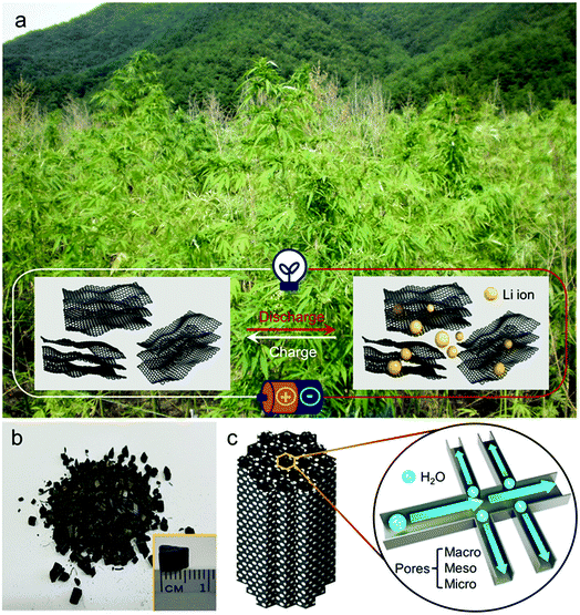
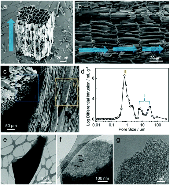
A hemp field from where the hemp stem was harvested as one of the by-products is shown in the photograph in Fig. 1a, with the illustration of hemp-derived carbon as the host material for lithium storage. As described in the experimental section, hemp stem was ground with a knife mill into smaller particles (less than 1.5 mm) in a chip-like form that is maintained after the activation process (Fig. 1b). As illustrated in Fig. 1c, during activation, steam flows in the reactor along the vertical direction to form an inter-connected pore network in the carbon, with hierarchically porous carbon consisting of micro-, meso-, and macro-pores, which were further investigated.FE-SEM images (Fig. 2a–c) show the morphologies of carbon after activation process. As shown in Fig. 2a, at higher magnification than that shown in Fig. 1b, the structure of the chip-shaped carbon is observed as a bundle of pores of ca. 10 μm in diameter, which results from the primary flow of steam in the reactor, as indicated by the blue arrow. The interior morphology of carbon shown in Fig. 2b seems to be a xylem structure composed of vessel elements that transport water and minerals from roots to all other parts of the plant; such vessels are hollow with no contents and separated by the carbon wall.27 It can be considered that steam passing through the carbon interior enables carbon to have this channel-like form with a hollow structure. Along with the channel-shaped pores (blue box I, Fig. 2c), the steam flow vertical to the main stream is reflected generates small pores on the carbon wall (yellow box II), which implies the development of macro-pores with dual pore-size distribution. Indeed, as shown in Fig. 2d, the channel-shaped pores and macro-porous walls of carbon are confirmed by pores of several tens of micrometers (I) and several micrometers (II), respectively. The structure of hemp-derived carbon was further examined using HR-TEM images, as shown in Fig. 2e–g. To conduct TEM analysis, the chip-shaped carbon was ground by hand; the corresponding carbon fragment is shown in Fig. 2e. The chip-like form breaks into small fragments of several tens of micrometers even during the sampling for SEM analysis (Fig. S2†), which confirms that the material hardness is poor enough to ground by hand. As magnification is increased, meso- and/or micro-pores are observed with different transparencies of the carbon fragments, as indicated by the black arrows in Fig. 2f, implying the abundance of nano-pores.28 In addition, Fig. 2g presents that the hemp-derived carbon is composed of randomly oriented small graphitic sheets, which forms an amorphous carbon structure.28,29 To quantitatively identify the residue materials in the hemp-derived carbon, the inorganic compositions were analyzed, and the presence of calcium (Ca), phosphorous (P), magnesium (Mg), potassium (K), and sodium (Na) were confirmed (Table S1†). In general, the concentrations of inorganic matter in woody biomasses, including hemp, are much lower than those in algae biomass.30–32
As described above, because the carbon after activation process was obtained as a chip-shaped reaction product, hand-milling in a mortar was necessary to form the powder needed for electrode fabrication. In this study, a ball-milling process for the hemp-derived carbon was designed with an intention to obtain finer powder than that from hand-milling. As shown in Fig. 3a, the crystalline structures of both natural and milled hemp-derived carbons were investigated by XRD analysis. Two peaks at ca. 23° and 43° (indicated by the area with diagonal lines) can be respectively assigned to the (002) and (100) reflections of typical graphite, and the considerable broadness of these peaks is indicative of the defective structure of the amorphous carbons.29 The two peaks become sharp and narrow in case of the milled hemp carbon, implying that the ball-milling process increases the extent of graphitization in the amorphous carbon.33 Graphitization is a process of transformation from metastable non-graphitic carbon to graphitic carbon.34 Ball-milling of amorphous carbon as well as catalytic pyrolysis of carbon precursors are known strategies to obtain partially graphitic carbons.33,35 In addition to the (002) and (100) reflections, several peaks are observed in the XRD patterns of both carbons, which can be attributed to the inorganic matter such as K, Ca, P, and Mg, as confirmed by ICP analysis. To further investigate the graphitic nature of carbon, Raman spectroscopy was performed on the hemp-derived carbons (Fig. 3b). Two major characteristic peaks at ca. 1331 cm−1 and 1592 cm−1 are observed, which correspond to the typical features of disordered graphite, i.e., crystal defects (D band) and ideal graphite (G band), respectively.36,37 The ratio of intensities of D and G band (ID/IG, denoted by R) denotes the extent of graphitization. Enhanced partial graphitization in amorphous carbon during the ball-milling process is confirmed from the Raman spectra of milled hemp, as observed in Fig. 3b.33,35 Moreover, it is known that the value of R is related to the size of in-plane crystallite of graphite (denoted by Lc), as expressed by an empirical formula Lc = 4.4/R.38 Lc was calculated as ca. 4.87 nm and 4.98 nm for natural hemp and milled hemp, respectively, indicating that the size of the in-plane graphite crystallite increases when the amorphous carbon undergoes the ball-milling process. Thus, it can be concluded that ball-milling of amorphous carbon from natural hemp enhances the extent of graphitization in the microcrystalline structure. Fig. 3c shows the C K-edge XANES spectra of the hemp-derived carbons and graphite reference, in both surface-sensitive total electron yield (TEY) and bulk-sensitive fluorescence yield (FY) modes. In TEY C K-edge spectra, all the samples, including graphite, have two main features at ca. 285.8 eV and 293 eV, which are assigned to the π* and σ* bands, respectively. The π* feature is typical of C![[double bond, length as m-dash]](https://www.rsc.org/images/entities/char_e001.gif) C bond (sp2) above and below the plane, while the σ* feature is typical of in-plane C–C bond (sp3).36,37 In addition, a wide feature centered at ca. 289.5 eV is observed between the π* and σ* features in the XANES spectra due to the physically adsorbed or chemically grafted molecules.39,40 Compared with TEY mode, a clear distinction of spectral profiles is observed between the hemp-derived carbons and the graphite in FY C K-edge XANES spectra. Prior to the π* feature at ca. 285.8 eV, one new peak at ca. 283 eV, which is ascribed to π′*, is observed only in the spectrum of the hemp-derived carbons, supporting the fact that the amorphous carbon in natural and milled hemps have a disordered structure because this peak is related with the structural defects in graphene.41,42 The inset in Fig. 3c clearly displays the peaks from adsorbed or grafted molecules, along with the π′* feature. Although the assignment of π′* feature is controversial, it is stronger in natural and milled hemps than in graphite, suggesting that it is contributed from H- and O-related bonds in the hemp-derived carbons.39,40
C bond (sp2) above and below the plane, while the σ* feature is typical of in-plane C–C bond (sp3).36,37 In addition, a wide feature centered at ca. 289.5 eV is observed between the π* and σ* features in the XANES spectra due to the physically adsorbed or chemically grafted molecules.39,40 Compared with TEY mode, a clear distinction of spectral profiles is observed between the hemp-derived carbons and the graphite in FY C K-edge XANES spectra. Prior to the π* feature at ca. 285.8 eV, one new peak at ca. 283 eV, which is ascribed to π′*, is observed only in the spectrum of the hemp-derived carbons, supporting the fact that the amorphous carbon in natural and milled hemps have a disordered structure because this peak is related with the structural defects in graphene.41,42 The inset in Fig. 3c clearly displays the peaks from adsorbed or grafted molecules, along with the π′* feature. Although the assignment of π′* feature is controversial, it is stronger in natural and milled hemps than in graphite, suggesting that it is contributed from H- and O-related bonds in the hemp-derived carbons.39,40
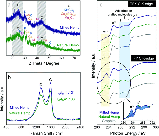 | ||
| Fig. 3 Characterization of hemp-derived carbons. (a) XRD patterns, (b) Raman spectra, and (c) XANES spectra at C K-edge of natural hemp and milled hemp. | ||
To analyze surface area and porosity, N2 adsorption/desorption isotherms and pore size distribution of the hemp-derived carbons were investigated (Fig. 4). Both hemp carbons show a type IV pattern in their isotherms with a distinct hysteresis loop at ca. 0.5 P P0−1, associated with the capillary condensation that takes place in meso-pores (Fig. 4a).43 The surface areas of natural and milled hemp were obtained as ca. 605 m2 g−1 and 526 m2 g−1, respectively. From the pore size distributions in Fig. 4b, the reason for the slightly decreased surface area in the milled hemp carbon is ascribed to the considerably decreased micro-pores after ball-milling. However, volume fraction of mesopores is significantly enhanced from 26% to 47% with ball-milling. Although further work is needed to elucidate the effect of ball-milling on porosity,44 presently, we can confirm that the hierarchically porous structure with dual mesopore system is developed in both hemp-derived carbons. Moreover, the ball-milling process introduces increased mesopores as well as decreased micropores in the amorphous carbon.
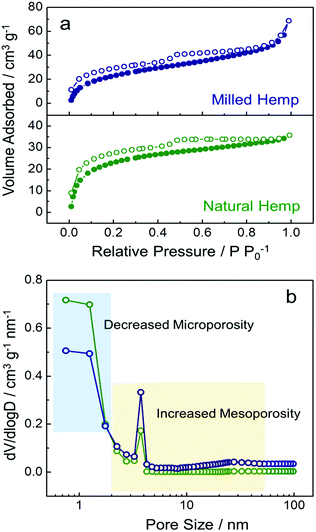 | ||
| Fig. 4 Characterization of natural hemp and milled hemp. (a) N2 adsorption/desorption isotherms and (b) pore size distributions. | ||
To investigate the electrochemical activity of hemp-derived carbon electrodes, cyclic voltammetry (CV) was performed in the range of 0.01–3 V at a scan rate of 0.05 mV s−1, as shown in Fig. 5. In electrodes of both natural and milled hemp, higher charge is involved in the first reduction process than in the first oxidation process, which is ascribed to electrolyte decomposition resulting in the irreversible formation of SEI layer at the first cathodic peak at 0.5–0.7 V. Insertion of Li+ into carbon starts below 1 V and majority Li+ insertion occurrs below 0.4 V. The corresponding extraction of Li+ from carbon is observed at 0.1–0.5 V.45,46 The electrochemical reaction above 1 V is understood as the discharge/charge process in electrochemical double-layer capacitors (EDLCs), which is typically similar to the electrochemical behavior of non-graphitic carbon anodes.47 Because the CV curve normalized by mass quantitatively represents the reactive surface area of an electrode, the wider surface area of milled hemp electrode compared with the natural hemp electrode, as distinguished by the dashed regions in Fig. 5, implies that the milled hemp electrode stores more Li+ than the natural hemp electrode during the second reduction and oxidation processes.
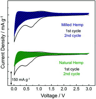 | ||
| Fig. 5 Electrochemical behavior of natural hemp and milled hemp electrodes in the first two CV curves. | ||
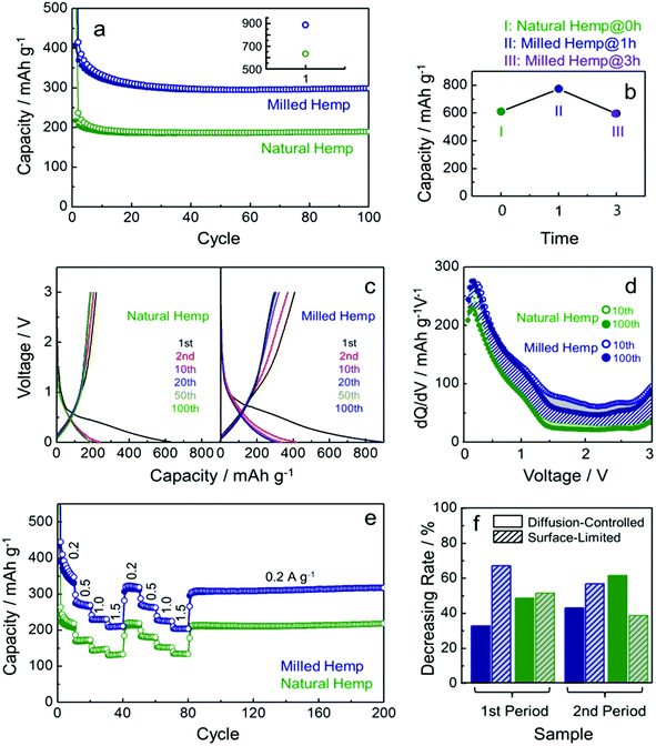
A series of electrochemical measurements of milled hemp and natural hemp electrodes for evaluating their lithium storage properties as anode materials for LIB were conducted (Fig. 6). Fig. 6a shows the cycling performance of both electrodes at a constant current density of 300 mA g−1. Although the capacities of both electrodes degrade until 20 cycles, they exhibit stable capacity retention till the 100th cycle. Compared with the natural hemp electrode, higher capacity is observed for the milled hemp electrode during the first 100 cycles. Charge capacity of natural hemp and milled hemp electrodes at the 100th cycle is 190 mA h g−1 and 300 mA h g−1, respectively. The capacity of 190 mA h g−1 at the 100th cycle with stable capacity retention indicates that natural hemp reversibly delivers 0.51 lithium per 6 carbons. For the milled hemp electrode, enhanced capacity of 300 mA h g−1 is achieved, which is better than48–50 or comparable51–55 to that of biomass-derived carbon anodes reported in recent years. As observed, the lithium storage capacity depends on whether ball-milling was conducted or not; therefore, for optimizing the condition, the ball-milling time was extended to 3 h. Fig. 6b shows the 1st discharge capacity as a function of ball-milling time, where discharge capacities of 611 mA h g−1, 774 mA h g−1, and 596 mA h g−1 are obtained for natural hemp@0 h, milled hemp@1 h, and milled hemp@3 h electrodes, respectively. Natural hemp@0 h, milled hemp@1 h, and milled hemp@3 h corresponds respectively to natural hemp electrode without ball-milling and milled hemp electrodes with ball-milling times of 1 h and 3 h. The milled hemp@1 h electrode consistently yielded the best capacity during 100 cycles, as shown in Fig. S3.† Consequently, the ball-milling time was controlled at 1 h for subsequent experiments with the natural hemp electrode studied as the control. Voltage profiles of natural hemp and milled hemp electrodes are shown in Fig. 6c, where the first discharge/charge capacities are 630 mA h g−1/217 mA h g−1 and 886 mA h g−1/408 mA h g−1, respectively. The decrease in irreversible capacity of milled hemp is presumably due to the development of crystallinity and a densely packed structure after ball-milling.56–63 No distinct plateau is observed below 0.4 V, which is characteristic of lithium storage in amorphous carbon with a low extent of graphitization. In addition, we can seen the slope inflection in the charge profile with a fiducial point at ∼1 V, which suggests that the de-lithiation process can be separated into two parts at around 1 V45,46 as follows: (i) below 1 V (0.01–1 V), de-intercalation occurs from the interlayer of carbon by lithium diffusion and (ii) above 1 V (1–3 V), desorption occurs at the surface of carbon via EDLCs-like capacitive behavior.47 To understand the lithium storage process in detail, differential capacity profiles (dQ/dV vs. voltage) of natural and milled hemp electrodes after 10th and 100th cycles were compared (Fig. 6d). First, the wider areas below 1 V compared with those above 1 V in all the differential capacity profiles imply that lithium storage is predominant through diffusion for both electrodes, with higher contribution from the bulk than the surface. Second, robust bulk utilization of both electrodes is attributed to the decrease in capacity of the milled hemp electrode for capacitive lithium storage, as indicated by the grey area. Third, compared with the natural hemp electrode, the increased capacity of the milled hemp electrode originates from both reaction processes (i) and (ii), with a positive difference in overall voltage ranges (diagonal blue lines). It is suggested that the structure of milled hemp is favorable for both bulk and surface utilizations. In particular, higher capacitive lithium storage of the milled hemp electrode than the natural hemp electrode, in spite of its lower surface area, can be due to increased electrolyte-accessible surface area from mesopores instead of micro-pores clogged by SEI and side reactions.25,26 Rate capability was evaluated by increasing the current density from 0.2 A g−1 to 1.5 A g−1 and then decreasing back to 0.2 A g−1 in two consecutive cycles, as shown in Fig. 6e. For both electrodes, although the initial charge capacity gradually decreases during the first 10 cycles, stable capacity retention and good cycling stability up to 200 cycles is exhibited. Rate capacity of ∼130 mA h g−1 and ∼210 mA h g−1 are achieved for natural hemp and milled hemp electrodes, respectively at the first 1.5 A g−1 cycle, and maintained at a similar level even at the second 1.5 A g−1 cycle. In spite of continuous cycling, when the current density returns to 0.2 A g−1, capacities of both electrodes are considerably recovered, demonstrating good rate capability. Fig. S4† compares the rate capability of milled hemp with other biomass-derived carbons reported in recent years, which again confirms the excellent rate capability of hemp-derived carbon through the ball-milling process. Moreover, the contribution of diffusion-controlled intercalation/de-intercalation and surface-limited adsorption/desorption was quantitatively investigated (Fig. 6f). The value of decreasing rate was calculated by subtracting the differential capacity profile at 0.2 A g−1 from that at 1.5 A g−1 at 1 V, and subsequently dividing into two reaction parts, i.e., bulk (below 1 V) and surface (above 1 V) reactions. All of the differential capacity profiles for these calculations are displayed in Fig. S5.† As the current density increases from 0.2 A g−1 to 1.5 A g−1, diffusion-controlled intercalation of the milled hemp electrode is less deteriorated compared with that of the natural hemp electrode in the 1st period. The facile Li+ diffusion into bulk in the milled hemp electrode is consistently retained in the 2nd period. Furthermore, priority of bulk utilization in natural hemp is even reversed, which again confirms that the structure of milled hemp is favorable for bulk diffusion.
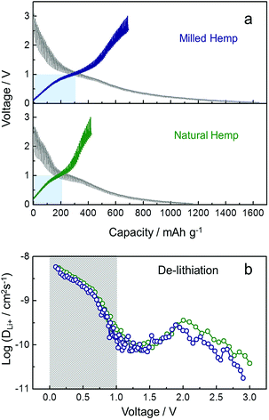
To understand the kinetics of hemp-derived carbon electrodes, GITT analysis was employed (Fig. 7), and the Li+ diffusion coeff-icient (DLi+) was calculated by using the following equation based on Fick's law:
Conclusions
Carbon from hemp stem, as a biomass precursor, was prepared using a simple, low-cost, and environment-friendly method by physical activation using only steam. The partially graphitic carbon with a hierarchically porous structure is developed in the hemp-derived carbon, which for the first time was directly applied as an anode material for LIB. In addition, ball-milling the hemp-derived carbon can control its physical properties, such as crystallinity and porosity. Consequently, enhanced graphitization and mesoporosity are simultaneously observed in the milled hemp electrode. While the natural hemp electrode itself delivers a reversible capacity of 190 mA h g−1 at a rate of 300 mA g−1 after 100 cycles, the capacity of the milled hemp electrode increases to 300 mA h g−1, along with excellent rate capability of 210 mA h g−1 even at a considerably high rate of 1.5 A g−1, suggesting that ball-milling leads to enhanced electrochemical properties for lithium storage and transport. Both the increase in diffusion-controlled intercalation/deintercalation and surface-limited adsorption/desorption contribute to the enhanced capacity of milled hemp, which is elucidated by the advantage of enhanced graphitization and mesoporosity for lithium diffusion. This study explores the potential of hemp for its utilization in storage and transport of lithium and demonstrates that hemp-derived carbon can be a promising material for obtaining carbon electrode in energy storage devices.Conflicts of interest
There are no conflicts to declare.Acknowledgements
J. H. Um acknowledges support by Basic Science Research Program through the NRF (NRF-2016R1A6A3A11932369). This work was supported by the National Research Foundation of Korea (NRF) grant funded by the Korea government (MSIP) (No. NRF-2017R1A4A1015770). This study was also supported by the Institute for Basic Science (IBS) in Korea (IBS-R006-A2). Y.-H. Cho. acknowledges financial support from the Basic Science Research Program (2016R1D1A3B03934752) through the National Research Foundation of Korea (NRF), which is funded by the Ministry of Education. This research was supported by the Basic Science Research Program through the National Research Foundation of Korea (NRF), funded by the Ministry of Education, Science and Technology (NRF-2017R1E1A1A01074282).References
- M. Mohri, N. Yanagisawa, Y. Tajima, H. Tanaka, T. Mitate, S. Nakajima, M. Yoshida, Y. Yoshimoto, T. Suzuki and H. Wada, J. Power Sources, 1989, 26, 545–551 CrossRef.
- Z. Yang, J. Zhang, M. C. W. Kintner-Meyer, X. Lu, D. Choi, J. P. Lemmon and J. Liu, Chem. Rev., 2011, 111, 3577–3613 CrossRef PubMed.
- L. E. Downie, L. J. Krause, J. C. Burns, L. D. Jensen, V. L. Chevrier and J. R. Dahn, J. Electrochem. Soc., 2013, 160, A588–A594 CrossRef.
- Z. Li, J. Huang, B. Yann Liaw, V. Metzler and J. Zhang, J. Power Sources, 2014, 254, 168–182 CrossRef.
- P. Kalyani and A. Anitha, Int. J. Hydrogen Energy, 2013, 38, 4034–4045 CrossRef.
- Y. Yao and F. Wu, Nano Energy, 2015, 17, 91–103 CrossRef.
- A. A. Nunes, A. S. Franca and L. S. Oliveira, Bioresour. Technol., 2009, 100, 1786–1792 CrossRef PubMed.
- C. A. Toles, W. E. Marshall and M. M. Johns, Carbon, 1997, 35, 1407–1414 CrossRef.
- W. M. A. W. Daud and W. S. W. Ali, Bioresour. Technol., 2004, 93, 63–69 CrossRef PubMed.
- B. Cagnon, X. Py, A. Guillot, F. Stoeckli and G. Chambat, Bioresour. Technol., 2009, 100, 292–298 CrossRef PubMed.
- J. Deng, T. Xiong, H. Wang, A. Zheng and Y. Wang, ACS Sustainable Chem. Eng., 2016, 4, 3750–3756 CrossRef.
- R. R. Bansode, J. N. Losso, W. E. Marshall, R. M. Rao and R. J. Portier, Bioresour. Technol., 2003, 90, 175–184 CrossRef PubMed.
- J. Deng, M. Li and Y. Wang, Green Chem., 2016, 18, 4824–4854 RSC.
- Y. Gao, X. Chen, J. Zhang and N. Yan, Chempluschem, 2015, 80, 1556–1564 CrossRef.
- X. Chen, Y. Gao, L. Wang, H. Chen and N. Yan, Chempluschem, 2015, 80, 1565–1572 CrossRef.
- P. T. Williams and A. R. Reed, J. Anal. Appl. Pyrolysis, 2003, 70, 563–577 CrossRef.
- J. M. Rosas, J. Bedia, J. Rodríguez-Mirasol and T. Cordero, Ind. Eng. Chem. Res., 2008, 47, 1288–1296 CrossRef.
- E. Gümüşkaya, M. Usta and M. Balaban, Bioresour. Technol., 2007, 98, 491–497 CrossRef PubMed.
- H. Wang, Z. Xu, A. Kohandehghan, Z. Li, K. Cui, X. Tan, T. J. Stephenson, C. K. King'Ondu, C. M. B. Holt, B. C. Olsen, J. K. Tak, D. Harfield, A. O. Anyia and D. Mitlin, ACS Nano, 2013, 7, 5131–5141 CrossRef PubMed.
- J. M. Rosas, J. Bedia, J. Rodríguez-Mirasol and T. Cordero, Fuel, 2009, 88, 19–26 CrossRef.
- R. Yang, G. Liu, X. Xu, M. Li, J. Zhang and X. Hao, Biomass Bioenergy, 2011, 35, 437–445 CrossRef.
- M. H. Yang, D. S. Kim, J. W. Sim, J. M. Jeong, D. H. Kim, J. H. Choi, J. Kim, S. S. Kim and B. G. Choi, Appl. Surf. Sci., 2017, 407, 540–545 CrossRef.
- M. Yang, D. S. Kim, S. B. Hong, J. W. Sim, J. Kim, S. S. Kim and B. G. Choi, Langmuir, 2017, 33, 5140–5147 CrossRef PubMed.
- S. Dutta, A. Bhaumik and K. C.-W. Wu, Energy Environ. Sci., 2014, 7, 3574–3592 RSC.
- M. Broussely, P. Biensan, F. Bonhomme, P. Blanchard, S. Herreyre, K. Nechev and R. J. Staniewicz, J. Power Sources, 2005, 146, 90–96 CrossRef.
- D. P. Abraham, J. L. Knuth, D. W. Dees, I. Bloom and J. P. Christophersen, J. Power Sources, 2007, 170, 465–475 CrossRef.
- J. M. O. Scurlock, D. C. Dayton and B. Hames, Biomass Bioenergy, 2000, 19, 229–244 CrossRef.
- B. Campbell, R. Ionescu, Z. Favors, C. S. Ozkan and M. Ozkan, Sci. Rep., 2015, 5, 14575 CrossRef PubMed.
- A. M. Stephan, T. P. Kumar, R. Ramesh, S. Thomas, S. K. Jeong and K. S. Nahm, Mater. Sci. Eng., A, 2006, 430, 132–137 CrossRef.
- S. S. Kim, H. V. Ly, G. H. Choi, J. Kim and H. C. Woo, Bioresour. Technol., 2012, 123, 445–451 CrossRef PubMed.
- S. S. Kim, H. V. Ly, J. Kim, J. H. Choi and H. C. Woo, Bioresour. Technol., 2013, 139, 242–248 CrossRef PubMed.
- S. S. Kim, H. V. Ly, J. Kim, E. Y. Lee and H. C. Woo, Chem. Eng. J., 2015, 263, 194–199 CrossRef.
- S. Zhang, Y. Cui, B. Wu, R. Song, H. Song, J. Zhou, X. Chen, J. Liu and L. Cao, RSC Adv., 2014, 4, 505–509 RSC.
- M. Liu, L. Gan, W. Xiong, Z. Xu, D. Zhu and L. Chen, J. Mater. Chem. A, 2014, 2, 2555–2562 RSC.
- S. Yi, Z. Fan, C. Wu and J. Chen, Carbon, 2008, 46, 378–380 CrossRef.
- A. C. Ferrari and J. Robertson, Phys. Rev. B, 2000, 61, 14095–14107 CrossRef.
- K. N. Kudin, B. Ozbas, H. C. Schniepp, R. K. Prud’homme, I. A. Aksay and R. Car, Nano Lett., 2008, 8, 36–41 CrossRef PubMed.
- D. S. Knight and W. B. White, J. Mater. Res., 1989, 4, 385–393 CrossRef.
- H. K. Jeong, H. J. Noh, J. Y. Kim, M. H. Jin, C. Y. Park and Y. H. Lee, Europhys. Lett., 2008, 82, 67004 CrossRef.
- B. J. Schultz, C. J. Patridge, V. Lee, C. Jaye, P. S. Lysaght, C. Smith, J. Barnett, D. A. Fischer, D. Prendergast and S. Banerjee, Nat. Commun., 2011, 2, 372 CrossRef PubMed.
- A. Laikhtman, I. Gouzman, A. Hoffman, G. Comtet, L. Hellner and G. Dujardin, J. Appl. Phys., 1999, 86, 4192–4198 CrossRef.
- Y. H. Tang, T. K. Sham, Y. F. Hu, C. S. Lee and S. T. Lee, Chem. Phys. Lett., 2002, 366, 636–641 CrossRef.
- K. S. W. Sing, Pure Appl. Chem., 1985, 57, 603–619 Search PubMed.
- S. C. Peterson, M. A. Jackson, S. Kim and D. E. Palmquist, Powder Technol., 2012, 228, 115–120 CrossRef.
- K. Tang, R. J. White, X. Mu, M. M. Titirici, P. A. Van Aken and J. Maier, ChemSusChem, 2012, 5, 400–403 CrossRef PubMed.
- C. Huang, S. Zhang, H. Liu, Y. Li, G. Cui and Y. Li, Nano Energy, 2015, 11, 481–489 CrossRef.
- H. Zhou, S. Zhu, M. Hibino and I. Honma, J. Power Sources, 2003, 122, 219–223 CrossRef.
- J. Tang, V. Etacheri and V. G. Pol, ACS Sustainable Chem. Eng., 2016, 4, 2624–2631 CrossRef.
- Q. Han, Z. Yi, F. Wang, Y. Wu and L. Wang, J. Alloys Compd., 2017, 709, 227–233 CrossRef.
- R. R. Gaddam, D. Yang, R. Narayan, K. V. S. N. Raju, N. A. Kumar and X. S. Zhao, Nano Energy, 2016, 26, 346–352 CrossRef.
- C. Choi, S.-D. Seo, B.-K. Kim and D.-W. Kim, Sci. Rep., 2016, 6, 39099 CrossRef PubMed.
- J. Tang and V. G. Pol, Sci. Rep., 2016, 6, 20290 CrossRef PubMed.
- S. W. Han, D. W. Jung, J. H. Jeong and E. S. Oh, Chem. Eng. J., 2014, 254, 597–604 CrossRef.
- L. Wang, Z. Schnepp and M. M. Titirici, J. Mater. Chem. A, 2013, 1, 5269–5273 RSC.
- X. Sun, X. Wang, N. Feng, L. Qiao, X. Li and D. He, J. Anal. Appl. Pyrolysis, 2013, 100, 181–185 CrossRef.
- J. Eom and H. Kwon, J. Mater. Res., 2008, 23, 2458–2466 CrossRef.
- Z. Zhang, Y. Wang, Q. Tan, D. Li, Y. Chen, Z. Zhong and F. Su, Nanoscale, 2014, 6, 371–377 RSC.
- Z. Zhang, Z. L. Wang and X. Lu, ACS Nano, 2018, 12, 3587–3599 CrossRef PubMed.
- W. Weppner, J. Electrochem. Soc., 1977, 124, 1569 CrossRef.
- A. Pan, J. Liu, J.-G. Zhang, G. Cao, W. Xu, Z. Nie, X. Jie, D. Choi, B. W. Arey, C. Wang and S. Liang, J. Mater. Chem., 2011, 21, 1153–1161 RSC.
- J. S. Gnanaraj, M. D. Levi, E. Levi, G. Salitra, D. Aurbach, J. E. Fischer and A. Claye, J. Electrochem. Soc., 2001, 148, A525–A536 CrossRef.
- C. Garau, A. Frontera, D. Quiñonero, A. Costa, P. Ballester and P. M. Deyà, Chem. Phys., 2004, 297, 85–91 CrossRef.
- S. Sun, X. Zhao, M. Yang, L. Wu, Z. Wen and X. Shen, Sci. Rep., 2016, 6, 19564 CrossRef PubMed.
Footnote |
| † Electronic supplementary information (ESI) available. See DOI: 10.1039/c8ra06958a |
| This journal is © The Royal Society of Chemistry 2018 |

