 Open Access Article
Adsorption and photo-Fenton catalytic degradation of organic dyes over crystalline LaFeO3-doped porous silica†
Thi To Nga Phan,
Aleksandar N. Nikoloski,
Parisa Arabzadeh Bahri and
Dan Li *
*
Chemical and Metallurgical Engineering and Chemistry, School of Engineering and Information Technology, Murdoch University, Western Australia, Australia. E-mail: L.Li@murdoch.edu.au; Tel: +61 8 9360 2569
First published on 24th October 2018
Abstract
LaFeO3 (LFO)-doped mesoporous silica (HPS) (HPS-xLFO with theoretical LFO/silica molar ratio x = 0.075, 0.15, 0.3) was successfully prepared via impregnation of metal ions into the porous silica HPS-0LFO support and subsequent calcination. The characterization studies suggest that increasing the doping of LFO, which exhibited a particle size of ∼10–15 nm, in the silica support led to a reduction in surface area and bandgap of the resulting catalyst. The use of HPS-0.15LFO yielded a superior removal rate (98.9%) of Rhodamine B (RhB), thanks to the effective dark adsorption and visible light-induced photo-Fenton degradation, both of which were greater than those of pure LFO crystals. This enhancement could be explained by the unique properties of the mesoporous silica support. In particular, the wide-opening mesopores created a large surface area to dope LFO as active sites and minimize diffusion of RhB into pores during the photo-Fenton reaction. The photo-Fenton catalytic degradation of RhB could reach 98.6% within 90 min exposure to visible light irradiation under optimized conditions: RhB concentration = 10 mg L−1, catalyst dosage = 1 g L−1, pH = 6 and H2O2 = 15 mM. Moreover, the recycle and reuse test proved the good stability and repetitive use of HPS-0.15LFO for high performance RhB removal.
1. Introduction
Advanced oxidation processes (AOPs) have been considered as alternative and effective methods in treating various industrial wastewaters contaminated by dyes and organic compounds over the last few years. As one of the AOPs, the Fenton reaction, using the strong oxidant hydrogen peroxide to generate highly reactive hydroxyl radicals (˙OH), has attracted intensive research interest since the 1960s in the removal of a variety of recalcitrant organic contaminants.1 Typically, the Fenton process is conducted in a homogeneous way using dissolved ferrous ions and hydrogen peroxide as Fenton reagents. However, the application of the homogeneous Fenton process on an industrial scale is limited due to: (i) pH-dependent chemical reactivity of iron; (ii) difficulty and complexity in separation and recovery of metal ions from the final effluent.2 Therefore, research efforts have been directed towards designing heterogeneous iron-based Fenton-like catalysts, such as iron oxide,3 iron exchanged zeolite4 and iron supported porous material.5 Combined with visible light irradiation, the cost-effectiveness of a heterogeneous Fenton-like process for use in wastewater treatment has been seen as promising.6,7Perovskite materials having the generic formula of ABO3, in which A is typically an alkaline-earth or rare-earth element and B is a transition metal, have been found to exhibit high visible light photo-Fenton-like activity for dye degradation.8,9 Ju et al. found that EuFeO3 nanoparticles prepared by the sol–gel method and calcined at 750 °C yielded 71% removal rate in 5 mg L−1 Rhodamine B (RhB) solution after being exposed to visible light for 3 h, in the presence of 1 g L−1 catalyst and 0.05 mL H2O2.8 An and co-workers investigated the use of BiFeO3 heterogeneous photo-Fenton-like catalyst synthesized by the sol–gel method on the degradation of RhB, Methyl Violet (MV) and phenol.9 Their results revealed that with the assistance of visible light irradiation, the RhB, phenol and MV degradation rate constant (k), derived from the pseudo-first-order model, was increased by 1.95, 2.07 and 3.47 times, respectively, compared to that under the dark condition. The utilization of visible light enhanced the photocatalytic activity of BiFeO3 for pollutant degradation in the presence of H2O2.
The literature suggests that LaFeO3 (LFO), as a member of the group of perovskite materials, could be a promising heterogeneous catalyst in the photo-Fenton degradation of pollutants.10–13 In the photo-Fenton reaction, the pollutant is believed to be oxidized and degraded by the attack of the hydroxyl radicals; thereby it is necessary to increase the number of active sites on the catalyst surface and in turn enhance the contact area between the pollutant and the catalyst towards the optimization of pollutant removal. However, LFO crystals synthesized via the traditional sol–gel method normally possess small specific surface area, show no porosity and therefore have a limited amount of active sites for catalytic degradation,10,14 due to the high temperature usually used in the synthesis.
So far, there has been some effort contributed to the development of supported LFO catalysts with porosity for high-performance Fenton or photo-Fenton degradation of pollutants. A number of materials have been explored for use as the supports, such as montmorillonite,15 carbon spheres,16 mesoporous silicas,17,18 and graphene.19 In particular, mesoporous silicas have received recent research interest because of their unique features, including high specific surface area, tunable pore size and structure.20–23 Zhu's group successfully loaded LFO on SBA-15 mesoporous silica and investigated its Fenton-like catalytic activity for the oxidation of Rhodamine B (RhB), reactive brilliant red X-3B, direct scarlet 4BS and methylene blue (MB).17 The results showed that 80% and 66% of RhB and MB was removed after 60 min, respectively; whilst that for 4BS and X-3B was similar, approximately 42% (test conditions: 1 mL of 30 wt%H2O2, 0.1 g catalyst and 50 mL of 0.02 mmol L−1 dye solution). It was also concluded that SBA-15-supported LFO was more efficient than the bulk LFO in the catalysing oxidation of organic. Later the same group studied the role of silica, including porous (e.g. SBA-15, SBA-16, MCF) and non-porous silica powders, on RhB oxidative degradation using the supported LFO.24 Their results revealed that the LFO sample supported by MCF, which had randomly distributed pores and short pore length, exhibited the highest photocatalytic performance when compared to other LFO-doped samples. This suggests that the porous structure of the support plays an essential role in the adsorption of the organic, its transportation to active sites and eventually catalytic degradation.24 However, there have been few publications, exploring the use of silica-supported LFO for enhanced photo-Fenton degradation of organics under visible light irradiation. There have been no reports of studies to optimize its catalytic performance under different operational conditions or to investigate its feasibility for recycle and reuse; all of which is necessary information for practical utilization in wastewater treatment.
In this work, a type of mesoporous silica (HPS), which showed a unique fine pore system, narrow inner channels and wide outer pore opening,25 was selected as a support for different amounts of LFO doping to prepare heterogeneous photo-Fenton-like catalysts HPS-xLFO (with theoretical LFO/silica molar ratio x = 0.075, 0.15, 0.3). This unique mesoporous structure may endow great surface area for LFO doping and in turn would offer a large number of active sites. Meanwhile, its wider pore opening would greatly reduce the resistance to large organic molecules being transported into the pores and reaching active sites for catalytic degradation. RhB, a representative of xanthane dyes, is widely used in a variety of industries (e.g. textile, dyeing, paint and printing) and imposes hazardous effect on the environment and public health.26,27 Although significant effort has been concentrated on the application of methods, including adsorption,28 membrane separation,29 ion flotation30 and ozonation,31 to remove RhB from water, they have to date been found to be ineffective or uneconomical due to the stability of dye.26 In this study, we selected RhB as the model organic dye to investigate its removal effectiveness using HPS-xLFO via adsorption and photo-Fenton catalytic degradation. The effect of catalyst dosage, H2O2 concentration, solution pH and co-existing ions on the photo-Fenton removal of RhB was investigated; and its performance after recycling was also studied.
2. Experimental
2.1 Chemicals
Cyclohexane (C6H12; 99.9%), 1-pentanol (CH3(CH2)4OH; ≥99%), cetyltrimethylammonium bromide (CH3(CH2)15N(Br)(CH3)3; 99%), tetraethyl orthosilicate (Si(OC2H5)4; 99%), lanthanum nitrate hexahydrate (La(NO3)3·6H2O; 99.9%), citric acid (C6H8O7·H2O; ≥99.5%), H2O2 (30 wt%), and Rhodamine B (RhB; ≥95%) were purchased from Sigma-Aldrich. Iron nitrate nonahydrate (Fe(NO3)3·9H2O; 98–101%) was purchased from Alta Aesar. Urea (NH2CONH2) was obtained from Merck Pty Limited, Australia. Other chemicals were from Biolab Ltd in Australia. All of the chemicals were used without additional purification.2.2 Preparation of porous silica
Mesoporous silica (HPS-0LFO) support was synthesized according to a reported procedure.25 First of all, 2.7 mL tetraethyl orthosilicate (TEOS) was dissolved in the mixture with 1.5 mL 1-pentanol and 30 mL cyclohexane at the room temperature. The resulting solution was stirred for 5 h, followed by the addition of a mixture which was made up of 1.87 g cetyltrimethylammonium bromide (CTAB), 0.6 g urea, 30 mL deionized (DI) water. After stirring, the solution was transferred into a Teflon-lined autoclave (100 mL) and heated in an oven at 120 °C for 4 h. Finally, white precipitates were separated from the liquid, washed with acetone and DI water, dried in an oven and calcined in air at 550 °C for 6 h (heating rate of 1 °C min−1 from room temperature to 550 °C).2.3 Synthesis of LaFeO3-doped HPS
LaFeO3-doped mesoporous silica (HPS-xLFO) was synthesized by impregnation and subsequent calcination. Typically, 10 mmol La(NO3)3·6H2O, 10 mmol Fe(NO3)3·9H2O and 20 mmol citric acid was dissolved in a mixture of 10 mL DI water and 20 mL of ethanol to form a homogeneous solution at room temperature. After adding 2 g HPS-0LFO, the resulting suspension was stirred at room temperature for 3 h and then at 70 °C to evaporate the solvent, followed by drying at 80 °C and then calcination at 700 °C (heating rate of 2 °C min−1 from room temperature to 700 °C). The theoretical molar ratio between LaFeO3 (LFO) and silica in different samples was 0.075, 0.15 and 0.3. The corresponding catalysts were designated as HPS-0.075LFO, HPS-0.15LFO, and HPS-0.3LFO, respectively. For comparison, the sample, which was synthesized following the same above procedures in the absence of HPS, was denoted as LFO.2.4 Sample characterization
Powder X-ray diffraction (XRD) measurement was performed on a diffractometer (XRD, GBC eMMA), which was operated in the reflection mode with Cu Kα radiation (28 mA, 35 kV) at a step size of 1° min−1 in the range of 10–80°. The surface morphology and elemental composition of each sample was characterized using Scanning Electron Microscopy (SEM) (Zeiss 1555, VP-FESEM) at an accelerating voltage of 5 kV with energy dispersive X-ray spectrometry (EDS). The samples were loaded onto the carbon tape and coated by platinum. Transmission Electron Microscopy (TEM) analysis was performed on TEM-TITAN operating at 200 kV. The samples were dispersed in ethanol under ultrasonication and loaded onto carbon copper grid for TEM characterization. Nitrogen adsorption–desorption isotherms were measured at 77 K using SAPA2010 (Micromeritics Inc., USA). The samples were degassed at 200 °C overnight under vacuum.2.5 Removal of RhB from water
100 mL of RhB aqueous solution (10 mg L−1) was introduced into a cylindrical Pyrex vessel (300 mL), surrounded by a circulating water jacket to maintain solution temperature at 25 °C. 100 mg of HPS-xLFO (x = 0, 0.075, 0.15, 0.3) or 100 mg of LFO was added to the RhB solution; the resulting suspension was magnetically stirred in the dark for 90 min to investigate its adsorption of RhB in water. Samples were taken from the suspension at given period of times and centrifuged at 10![[thin space (1/6-em)]](https://www.rsc.org/images/entities/char_2009.gif) 000 rpm. The obtained supernatant was analysed using a Perkin Elmer Lambda 750 UV/Vis spectrometer to determine the concentration of RhB (Ci, mg L−1), compared to the initial concentration of RhB before adsorption (C, mg L−1).
000 rpm. The obtained supernatant was analysed using a Perkin Elmer Lambda 750 UV/Vis spectrometer to determine the concentration of RhB (Ci, mg L−1), compared to the initial concentration of RhB before adsorption (C, mg L−1).
The results showed that the adsorption–desorption equilibrium was achieved within 30 min. Therefore, the photo-Fenton catalytic degradation test was started after 30 min dark adsorption using the catalyst. Typically, 100 mL of RhB aqueous solution (10 mg L−1) was introduced into a cylindrical Pyrex vessel (300 mL), surrounded by a circulating water jacket to maintain solution temperature at 25 °C. 100 mg of HPS-xLFO (x = 0, 0.075, 0.15, 0.3) or LFO was added to the RhB solution; the resulting suspension was magnetically stirred in the dark for 30 min to reach adsorption–desorption equilibrium. After that, a xenon lamp (CEL-HX F300) with a 400 nm cut-off filter was used to provide visible light and 1 mL H2O2 was added to the suspension to initiate the photo-Fenton-like reaction. Samples were taken from the suspension at given periods of time and centrifuged at 10![[thin space (1/6-em)]](https://www.rsc.org/images/entities/char_2009.gif) 000 rpm. The obtained supernatant was analysed using Perkin Elmer Lambda 750 UV/Vis spectrometer to determine the concentration of RhB (Ct, mg L−1), as compared with the concentration of RhB before starting photo-Fenton-like degradation (C0, mg L−1).
000 rpm. The obtained supernatant was analysed using Perkin Elmer Lambda 750 UV/Vis spectrometer to determine the concentration of RhB (Ct, mg L−1), as compared with the concentration of RhB before starting photo-Fenton-like degradation (C0, mg L−1).
The reusability of the catalyst was assessed by repeating the photo-Fenton degradation test under the same reaction conditions after recovering HPS-0.15LFO from the solution.
3. Results and discussion
3.1 Characterization of HPS-xLFO
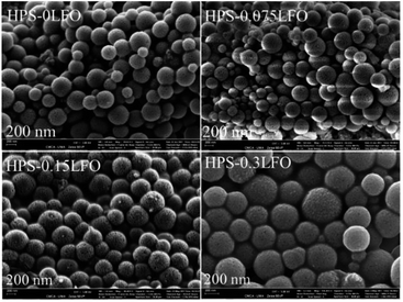
The general morphologies of HPS-xLFO (x = 0, 0.075, 0.15, 0.3) with different LFO loadings are presented in Fig. 1. The sample of HPS-0LFO exhibited monodispersed spheres with a particle diameter of ∼300–400 nm. The morphology of LFO-loaded HPS (HPS-0.075LFO, HPS-0.15LFO, and HPS-0.3LFO) was similar to that of HPS-0LFO, suggesting that the HPS support is stable during doping with LFO. No significant LFO crystals or clumps were seen separately from the particles of HPS-xLFO (x = 0.075, 0.15, 0.3).The morphology and size of HPS and HPS-0.15LFO observed by TEM (Fig. 2a and b) are consistent with those in Fig. 1. In Fig. 2a, the particles of HPS-0LFO exhibited a unique mesoporous structure. Compared with Fig. 2a, the TEM image of HPS-0.15LFO (Fig. 2b) shows that some small particles (e.g. indicated in red) were loaded in the HPS support. These particles were observed with an interplanar distance of 0.278 nm (Fig. 2c), which corresponds to the (121) crystal plane of LFO.32 The high-angle-annular dark-field (HAADF) scanning TEM image of HPS-0.15LFO (Fig. 2d), and the corresponding elemental mapping images (Fig. 2e) further confirm that LFO was loaded to the HPS support.
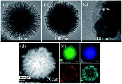 | ||
| Fig. 2 TEM images of (a) HPS-0LFO and (b) HPS-0.15LFO; (c) HRTEM image of HPS-0.15LFO; (d) HAADF scanning TEM image of HPS-0.15LFO and (e) the corresponding elemental mapping (Si, O, La, and Fe). | ||
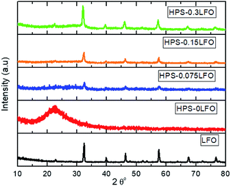
The XRD patterns of HPS-xLFO (x = 0, 0.075, 0.15, 0.3) are shown in Fig. 3; the XRD pattern of LFO synthesized without the use of HPS was included for comparison. A broad characteristic peak at 2θ = 23° was observed for the amorphous mesoporous SiO2, HPS-0LFO. As expected, the LFO loading affected the porous structure of the HPS support. The characteristic peak intensity of SiO2 considerably decreased with increased LFO loading in HPS, which is probably due to the partial or complete filling of LFO inside the HPS pores. The samples of HPS-0.075LFO, HPS-0.15LFO, and HPS-0.3LFO exhibited the characteristic diffraction peaks indexable to the orthorhombic structure of LFO (JCPDS no. 37-1493).33 No apparent characteristic peaks of impurities were detected, confirming the high purity of the samples.
The nitrogen adsorption–desorption isotherms and BJH pore size distribution curves of HPS-xLFO (x = 0, 0.075, 0.15, 0.3) are shown in Fig. 4. The N2 adsorption–desorption isotherm curves of all samples showed a type IV isotherm with H2-hysteresis loops (Fig. 4a), which suggests the characteristic of mesoporous structure.25 It can be seen from Fig. 4b that HPS possessed a broad pore size distribution with multimodal mesopores ranging from 15 nm to 30 nm. It is worth noting that the high BET surface area of 496.62 m2 g−1 was recorded for HPS-0LFO; whereas that of HPS-xLFO (x = 0.075, 0.15, 0.3) was considerably reduced from 349.52 m2 g−1 to 123.12 m2 g−1 as the theoretical molar ratio of LFO loading to silica increased from 0.075 to 0.3. The pore volume of HPS-xLFO showed a similar trend, from 2.34 cm3 g−1 (HPS-0LFO), 1.22 cm3 g−1 (HPS-0.075LFO), 0.47 cm3 g−1 (HPS-0.15LFO) to 0.27 cm3 g−1 (HPS-0.3LFO). The decrease of BET surface area and total pore volume accompanied with the increase of LFO loading could be attributed to the presence of LFO in the pores and channels of the HPS support. These results suggest that LFO was successfully incorporated into the mesopores of HPS. A low BET surface area of 8.06 m2 g−1 was observed for the LFO sample synthesized without the use of a HPS support. As can be seen, the LFO-doped HPS samples exhibited much higher specific surface area and presented accessible pores, providing more active sites and pathways for RhB removal.
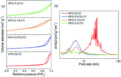 | ||
| Fig. 4 (a) N2 adsorption–desorption isotherms and (b) BJH pore size distributions of HPS-xLFO (x = 0, 0.075, 0.15, 0.3). | ||
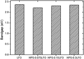
Fig. S1† presents the UV-vis absorption spectra of HPS-doped LFO as compared with that of LFO. All samples exhibited the broad absorption peaks in the visible region, implying they could absorb visible light. Fig. 5 presents the bandgap values of LFO and HPS-xLFO (x = 0.075, 0.15, 0.3). They were estimated from the interception of the straight line fitted the curve [F(R)hν]2 versus hν, in which F(R) is the Kubelka–Munk function and hν is the energy of the incident photon (shown in the inset of Fig. S1†). The corresponding bandgap was 2.21 eV, 2.31 eV, and 2.34 eV, respectively, for HPS-0.075LFO, HPS-0.15LFO, HPS-0.3LFO, which was narrower as compared with 2.36 eV for LFO. In the literature, Perathoner and co-workers also reported the improved effectiveness of light absorption of SBA15-supported TiO2, relative to TiO2.34
3.2 Adsorptive removal of RhB using HPS-xLFO
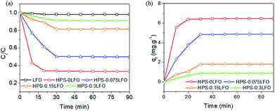
The photo-Fenton degradation of RhB generally takes place on the surface of catalyst; therefore the RhB adsorption capability of LFO or HPS-xLFO (x = 0, 0.075, 0.15, 0.3) is expected to affect its photocatalytic performance.24,35–37 Fig. 6a shows the adsorptive removal of RhB using LFO and HPS-xLFO (x = 0, 0.075, 0.15, 0.3), which was conducted in the dark for 90 min. Fig. 6b reveals the RhB adsorption capacity of the samples as a function of time.The adsorption kinetics were not in good agreement with the pseudo-first-order model, as revealed by the low values of r2 (r2 = 0.8161–0.9862) in Table S1.† On the other side, high correlation coefficients (r2 = 0.9661–0.9998; Table S1†) of the linear plots suggest the good agreement of the kinetic data with the pseudo-second-order model, which indicates the process is mainly chemisorption.
As shown above, the HPS-xLFO (x = 0, 0.075, 0.15, 0.3) samples exhibited better adsorption capability of RhB than LFO. This might be ascribed to their structural properties (specific surface area and porosity), which were seen in the SEM, TEM and nitrogen adsorption–desorption characterization. The porous structure of the HPS support (HPS-0LFO) was observed in the SEM and TEM images (Fig. 1 and 2), which could offer more space and pathways to facilitate the adsorption of RhB as compared with LFO solid crystals. Moreover, mesoporous silica material has an abundance of silanol groups (Si–OH) on the surface;38,39 whilst RhB molecules contain carboxyl groups. A hydrogen bond might be established between the functional groups of the HPS support and RhB,40 which would translate into higher RhB adsorption by HPS-xLFO than by LFO. HPS-0LFO exhibited the highest adsorption capacity as compared to other LFO-doped HPS samples (HPS-0.075LFO, HPS-0.15LFO and HPS-0.3LFO); since the doping of LFO into the HPS support reduced specific surface area, pore volume and number of surface silanol groups. The BET surface area and pore volume of the catalysts changed in a trend of HPS-0LFO > HPS-0.075LFO > HPS-0.15LFO > HPS-0.3LFO. This is consistent with the obtained results for RhB adsorption capability.
3.3 Photo-Fenton catalytic degradation of RhB using HPS-xLFO
To evaluate the photo-Fenton-like catalytic activity of HPS-xLFO (x = 0, 0.075, 0.15, 0.3), the degradation of RhB in the presence of H2O2 under visible light irradiation was carried out. The data were fitted with the pseudo-first-order kinetic model and the apparent rate constant was obtained from the slope of the straight line by plotting −ln(Ct/C0) as a function of time.Fig. S2† reveals no change in Ct/C0 in the absence of catalyst and H2O2, implying that RhB does not be self decompose under visible light irradiation. Without the use of catalyst, approximately 7% of RhB was removed in the presence of H2O2 and visible light. A limited amount of RhB (∼5%) was removed using just the catalyst of HPS-0.15LFO and exposure to visible light source. As compared with the results in Fig. 7, the use of H2O2 is indispensible for the efficient removal of RhB from water when using the as-prepared catalyst herein.
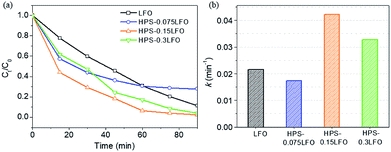
The photo-Fenton-like catalytic degradation of RhB using HPS-0.075LFO was 72.1%, which was slightly lower than that using LFO, which was 88.6%. The pseudo-first-order reaction constant of HPS-0.075LFO and HPS-0LFO was 0.0174 min−1 and 0.0215 min−1, respectively. The relatively lower degradation performance of HPS-0.075LFO might be explained by the small loading of LFO into the HPS support resulting in fewer active sites available for degradation. When the molar ratio of LFO loading and silica was increased to 0.15 the RhB degradation efficiency of HPS-0.15LFO reached 97.5%, with the pseudo-first-order reaction rate constant 0.0423 min−1. However, when using HPS-0.3LFO, the degradation efficiency was reduced slightly to 95.9% (the pseudo-first-order reaction rate constant was 0.0327 min−1). This could be attributed to excess LFO partially covering or blocking the pores in the HPS support; as a result, the transport of organic into pores and subsequently its degradation was hindered.
Note that, the use of HPS-0.15LFO and HPS-0.3LFO resulted in better removal of RhB (97.5% and 95.9%, respectively) than LFO (88.6%) in the photo-Fenton degradation. In particular, the theoretical molar ratio of LFO/silica in HPS-0.15LFO and HPS-0.3LFO was 0.15 and 0.3. No degradation of RhB was found when using the HPS support (HPS-0LFO) as the catalyst, suggesting the support plays no role in degradation reaction. That implies that for the same dosage of catalyst, the actual amount of LFO in the doped HPS participating in the reaction was much smaller but its activity was more efficient, as compared with the bulk LFO crystals. On the other side, the RhB adsorption using HPS-0.15LFO or HPS-0.3LFO was noticeable in Fig. 6, in contrast to the negligible adsorption using the bulk LFO crystals. This suggests that both of the LFO-doped catalysts could adsorb RhB from solution onto the silica support and guarantee the degradation to occur smoothly on the LFO active sites.24
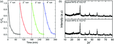
As can be seen above, the plain silica support HPS-0LFO could remove RhB to some level, mainly governed by adsorption (~65% shown in Fig. 6a). So far, various methods, including biological, physical and chemical ways, have been widely explored to remove organics and dyes from water. Adsorption, as a traditional method, only transfers dyes from water to another phase. It normally requires further treatment of saturated adsorbents after adsorption, e.g. disposal or regeneration. For example, in the case of this study, the use of high temperature (normally >500 °C) or organic solvent would be needed to regenerate dye-saturated adsorbents for recycle and reuse,41,42 which may add further cost and complexity to the process. Advanced oxidation process (AOPs) have shown advantageous features as compared with adsorption. Especially, the heterogenous AOPs (e.g. photo-Fenton) has demonstrated promising results for degradation of dyes to produce more biologically degradable and less toxic substances.43 In our study, the use of LFO doping onto HPS (e.g. HPS-0.15LFO) could achieve much better total removal rate of RhB (over 98%), as compared to only <75% using the parent HPS-0LFO. Note that, the regeneration process herein is simple and capable for scale-up; especially it required no high temperature calcination and organic solvent (the results of recycle and reuse were shown in 3.4.5). The photo-Fenton catalytic performance in terms of dye removal using HPS-0.15LFO was almost completely retained after 4 cycles of use.
Our work also compared the photo-Fenton catalytic performance of HPS-0.15LFO with that of Fe2O3-doped HPS using our HPS support (under the same molar ratio of loading). However, the preliminary results found that the degradation rate of plain Fe2O3 or its doped HPS was <70%, thus lower than that of HPS-0.15LFO. More systematic study is undertaken to reveal the reasons.
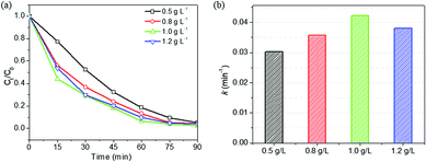
As discussed above, HPS-0.15LFO exhibited the greatest reaction rate constant, best degradation performance and highest removal efficiency, among the samples of LFO-doped HPS, HPS support and LFO pure crystals. Therefore, we selected HPS-0.15LFO to study the effects of catalyst dosage, H2O2 centration, initial pH and co-existing ions on photo-Fenton degradation of RhB.
Interestingly, in the dark, HPS-0.15LFO yielded a degradation rate of 66.5% (Fig. S2†), revealing that HPS-0.15LFO can act as a heterogeneous Fenton-like catalyst.24 With the use of visible light, the degradation of RhB was significantly enhanced, up to 97.5%, strongly suggesting that the combination of HPS-0.15LFO catalyst, H2O2 and visible light is necessary to achieve efficient and effective removal of RhB.
3.4 Effect of operational parameters on photo-Fenton using HPS-0.15LFO
It might be attributed to the scavenging effect because of excess H2O2, as shown in eqn (1):45
| H2O2 + ˙OH → HO2˙ + H2O | (1) |
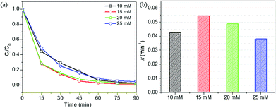
At high concentration of H2O2, H2O2 could act as a ˙OH radical scavenger, resulting in the reduced number of ˙OH radicals. Moreover, the generated HO2˙ would be less reactive than ˙OH;46 as a result, the RhB degradation efficiency decreased. The optimal H2O2 concentration for the photo-Fenton degradation of RhB using HPS-0.15LFO was found to be 15 mM.
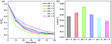
As reported in the literature,48,49 the low degradation% of RhB at high pH might be attributed to the decomposition of H2O2 into less reactive hydroperoxyl radicals and the restriction of ˙OH production in a basic medium. Moreover, in a solution with pH > 3.7 (pKa of RhB), RhB presents in zwitterionic form.26 At high pH, the zwitterionic form of RhB tends to form bigger molecules,50 which might hinder the transport and entry of dye molecules into the pores of HPS-15LFO. In addition, the zwitterionic form of RhB molecules at high pH are less attackable by ˙OH radicals.26 These effects could explain the decrease in the degradation of RhB which was observed at high pH (e.g. pH > 6). Fig. 10b shows that the pseudo-first-order reaction rate constant k was the highest (0.0544 min−1) at pH = 6; as compared with 0.0404 min−1, 0.0346 min−1 and 0.0287 min−1 at pH = 7, 8 and 9, respectively. The maximum degradation efficiency of RhB (98.6%) was observed at pH = 6.
Note that the RhB degradation rate gradually decreased as the initial solution pH was reduced from 6 down to 4. Fig. 10b shows that the pseudo-first-order reaction rate constant k was 0.0369 min−1 and 0.0437 min−1, respectively at pH = 4 and 5; which was smaller than that at pH = 6 (0.0544 min−1), but still comparable or greater than those at pH > 6. Fig. S3† reveals the pHpzc of HPS-15LFO to be 6.39, using pH drift method.51–53 When the solution pH was below the pHpzc, the surface of HPS-15LFO was positively charged; and above the pHpzc, the surface was negatively charged. As the proton concentration increased at lower pH, RhB could be protonated to RhBH+ under the acidification with H+.54 The positively charged surfaces of HPS-0.15LFO might inhibit the adsorption of dye due to the repulsive force,54 resulting in the observed slight decrease of degradation rate.
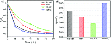
In Fig. 11a, the coexistence of NO3− ion could slightly improve the degradation efficiency. Similar results were also reported by previous studies.55,56 The pseudo-first-order reaction rate constant k was 0.0702 min−1 in the presence of 0.1 M NaNO3. This may be explained by the photolysis of NO3− to produce hydroxyl radicals via the following reactions:57,58
| NO3− + hν → [NO3−]* | (2) |
| [NO3−]* → NO2˙ + O−˙ | (3) |
| O−˙ + H2O → ˙OH + OH− | (4) |
The presence of Cl− and SO42− showed an inhibitory effect on the RhB photo-Fenton catalytic degradation using HPS-0.15LFO. The pseudo-first-order reaction rate constant k was 0.0413 and 0.0280 min−1 when NaCl or Na2SO4 was added, in comparison of 0.0544 min−1 in the absence of coexisting ions. Eskandarloo et al. reported that Cl− could act as an effective scavenging agent of holes and/or hydroxyl radicals,59 thus lowering photo-Fenton-like catalytic degradation efficiency. This result is also in a good agreement with the literature.60 Similarly, the inhibitory effect of SO42− on the degradation was suggested by Konstantinou and co-workers that SO42− react with h+ and ˙OH to form less reactive species SO4˙− (eqn (5) and (6)):61
| SO42− + h+ → SO4˙− | (5) |
| SO42− + ˙OH → SO4˙− + OH− | (6) |
On the other side, the competitive adsorption could more or less contribute to the observed reduction of degradation rates. SO42−, as the double charged anion, might be easier to adsorb on the surface of HPS-0.15LFO as compared to NO3− and Cl−, which potentially blocked more active site and in turn reduced degradation rate more significantly.56 The large molecular size of SO42− might also enhance steric hindrance and reduce the contact of RhB with HPS-0.15LFO. Consequently, the degradation efficiency appeared slightly lower in the presence of SO42− as compared with Cl−.
![[triple bond, length as m-dash]](https://www.rsc.org/images/entities/char_e002.gif) FeIII + H2O2 → FeIII + H2O2 → ![[triple bond, length as m-dash]](https://www.rsc.org/images/entities/char_e002.gif) FeIIIH2O2 FeIIIH2O2
| (7) |
![[triple bond, length as m-dash]](https://www.rsc.org/images/entities/char_e002.gif) FeIIIH2O2 → FeIIIH2O2 → ![[triple bond, length as m-dash]](https://www.rsc.org/images/entities/char_e002.gif) FeII + HO2˙ + H+ FeII + HO2˙ + H+
| (8) |
![[triple bond, length as m-dash]](https://www.rsc.org/images/entities/char_e002.gif) FeIII + HO2˙ + H+ → FeIII + HO2˙ + H+ → ![[triple bond, length as m-dash]](https://www.rsc.org/images/entities/char_e002.gif) FeII + O2 + 2H+ FeII + O2 + 2H+
| (9) |
![[triple bond, length as m-dash]](https://www.rsc.org/images/entities/char_e002.gif) FeII + H2O2 → FeII + H2O2 → ![[triple bond, length as m-dash]](https://www.rsc.org/images/entities/char_e002.gif) FeIII + ˙OH + OH− FeIII + ˙OH + OH−
| (10) |
| HPS-0.15LFO + hν → e− + h+ | (11) |
| H2O2 + e− → ˙OH + OH− | (12) |
| dye + hν → dye* | (13) |
| dye* + h+ → dye+ | (14) |
| ˙OH + dye (or dye+) → degradation products | (15) |
It is commonly accepted that the interfacial Fe atoms (denoted as ![[triple bond, length as m-dash]](https://www.rsc.org/images/entities/char_e002.gif) FeIII) of perovskite-based catalysts can activate H2O2 to form hydroxyl radicals (˙OH) during the Fenton-like reaction (eqn (7)–(10)).8,62 The ˙OH radical is considered as a strong oxidizing agent because of its standard redox potential (+2.8 V), which could oxidize most of the dyes to the mineral end-products.63 Meanwhile, HPS-0.15LFO can absorb visible light to produce photogenerated electron–hole pairs (eqn (11));64 the electron is trapped by H2O2 to generate highly reactive ˙OH (eqn (12)) and the hole is also an important active species to directly mineralize organic (eqn (14)).62 Note that the role of h+ in oxidation process of organics has so far remained inconclusive.65 Some studies speculated that h+ could activate dye*, which was formed after light absorption of dye (eqn (13)), into dye+ (eqn (14)); dye+ or dye was then oxidized by ˙OH radical (eqn (15)).66,67
FeIII) of perovskite-based catalysts can activate H2O2 to form hydroxyl radicals (˙OH) during the Fenton-like reaction (eqn (7)–(10)).8,62 The ˙OH radical is considered as a strong oxidizing agent because of its standard redox potential (+2.8 V), which could oxidize most of the dyes to the mineral end-products.63 Meanwhile, HPS-0.15LFO can absorb visible light to produce photogenerated electron–hole pairs (eqn (11));64 the electron is trapped by H2O2 to generate highly reactive ˙OH (eqn (12)) and the hole is also an important active species to directly mineralize organic (eqn (14)).62 Note that the role of h+ in oxidation process of organics has so far remained inconclusive.65 Some studies speculated that h+ could activate dye*, which was formed after light absorption of dye (eqn (13)), into dye+ (eqn (14)); dye+ or dye was then oxidized by ˙OH radical (eqn (15)).66,67
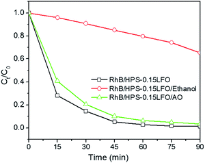
To investigate the mechanism for photo-Fenton-like degradation over HPS-0.15LFO, the effect of active species, such as hole (h+) and hydroxyl radicals (˙OH), in the process was explored. Ethanol and ammonium oxalate (AO) were selected for use as the scavengers of ˙OH and h+ in the trapping experiment, respectively.68,69 Fig. 13 shows that when AO was introduced, no significant change was observed in the photo-Fenton catalytic RhB degradation. However, when ethanol was added into the reaction solution, the 90 min RhB degradation efficiency was suppressed to only 47.3%. It suggests that ˙OH play a more significant role in the photo-Fenton-like catalytic RhB degradation using HPS-0.15LFO.
4. Conclusions
The catalyst LaFeO3 supported by mesoporous silica (HPS) was successfully synthesized by the method of impregnation and subsequent calcination. The characterization results showed that the sample of HPS-0.15LFO with a theoretical LFO/silica molar ratio of 0.15 exhibited great surface area and a narrow bandgap. It exhibited higher total removal rate of RhB (98.9%) from water compared to the others with different loadings of LFO; which was contributed to dark adsorption (18.5% in 30 min) and photo-Fenton degradation (98.6% in 90 min in the presence of 15 mM H2O2, 1 g L−1 catalyst and pH of 6). The optimum operational conditions for photo-Fenton degradation using HPS-0.15LFO were found to be: RhB concentration = 10 mg L−1, catalyst dosage = 1 g L−1, pH = 6 and H2O2 = 15 mM. It is suggested that in this reaction, the hydroxyl radicals were the main active species. The high degradation efficiency, good reusability and stability may enable promising industrial application of HPS-0.15LFO as a visible-light-driven photo-Fenton-like catalyst for removal of organic from wastewater.Conflicts of interest
There are no conflicts to declare.Acknowledgements
T. Phan's PhD study is supported by Australia Awards Scholarship. This research was funded by Murdoch SEIT Small Grant Scheme (2016). The authors acknowledge the facilities, and the scientific and technical assistance of the Australian Microscopy & Microanalysis Research Facility at the Centre for Microscopy, Characterisation & Analysis, The University of Western Australia, a facility funded by the University, State and Commonwealth Governments.Notes and references
- E. Neyens and J. Baeyens, J. Hazard. Mater., 2003, 98, 33–50 CrossRef CAS PubMed.
- M. R. Carrasco-Díaz, E. Castillejos-López, A. Cerpa-Naranjo and M. L. Rojas-Cervantes, Chem. Eng. J., 2016, 304, 408–418 CrossRef.
- K. Rusevova, F.-D. Kopinke and A. Georgi, J. Hazard. Mater., 2012, 241, 433–440 CrossRef PubMed.
- M. Tekbaş, H. C. Yatmaz and N. Bektaş, Microporous Mesoporous Mater., 2008, 115, 594–602 CrossRef.
- J. H. Ramirez, F. J. Maldonado-Hódar, A. F. Pérez-Cadenas, C. Moreno-Castilla, C. A. Costa and L. M. Madeira, Appl. Catal., B, 2007, 75, 312–323 CrossRef CAS.
- H. Zheng, Y. Pan and X. Xiang, J. Hazard. Mater., 2007, 141, 457–464 CrossRef CAS PubMed.
- J. M. Chacón, M. T. Leal, M. Sánchez and E. R. Bandala, Dyes Pigm., 2006, 69, 144–150 CrossRef.
- L. Ju, Z. Chen, L. Fang, W. Dong, F. Zheng and M. Shen, J. Am. Ceram. Soc., 2011, 94, 3418–3424 CrossRef CAS.
- J. An, L. Zhu, Y. Zhang and H. Tang, J. Environ. Sci., 2013, 25, 1213–1225 CrossRef CAS.
- Y. Nie, L. Zhang, Y.-Y. Li and C. Hu, J. Hazard. Mater., 2015, 294, 195–200 CrossRef CAS PubMed.
- L. Li, X. Wang and Y. Zhang, Mater. Res. Bull., 2014, 50, 18–22 CrossRef CAS.
- T. T. N. Phan, A. N. Nikoloski, P. A. Bahri and D. Li, J. Ind. Eng. Chem., 2018, 61, 53–64 CrossRef CAS.
- T. T. N. Phan, A. N. Nikoloski, P. A. Bahri and D. Li, J. Environ. Chem. Eng., 2018, 6, 1209–1218 CrossRef CAS.
- K. Rusevova, R. Köferstein, M. Rosell, H. H. Richnow, F.-D. Kopinke and A. Georgi, Chem. Eng. J., 2014, 239, 322–331 CrossRef CAS.
- K. Peng, L. Fu, H. Yang and J. Ouyang, Sci. Rep., 2016, 6, 19723 CrossRef CAS PubMed.
- K. Wang, H. Niu, J. Chen, J. Song, C. Mao, S. Zhang and Y. Gao, Appl. Surf. Sci., 2017, 404, 138–145 CrossRef CAS.
- P. Xiao, J. Hong, T. Wang, X. Xu, Y. Yuan, J. Li and J. Zhu, Catal. Lett., 2013, 143, 887–894 CrossRef CAS.
- H. Su, L. Jing, K. Shi, C. Yao and H. Fu, J. Nanopart. Res., 2010, 12, 967–974 CrossRef CAS.
- X. Ren, H. Yang, S. Gen, J. Zhou, T. Yang, X. Zhang, Z. Cheng and S. Sun, Nanoscale, 2016, 8, 752–756 RSC.
- S. Nguyen, V. Szabo, D. T. On and S. Kaliaguine, Microporous Mesoporous Mater., 2002, 54, 51–61 CrossRef CAS.
- J. Zhao, Y. Liu, X. Li, G. Lu, L. You, X. Liang, F. Liu, T. Zhang and Y. Du, Sens. Actuators, B, 2013, 181, 802–809 CrossRef CAS.
- W. Huang, X. Yu, J. Tang, Y. Zhu, Y. Zhang and D. Li, Microporous Mesoporous Mater., 2015, 217, 225–232 CrossRef CAS.
- K. Zhang, L.-L. Xu, J.-G. Jiang, N. Calin, K.-F. Lam, S.-J. Zhang, H.-H. Wu, G.-D. Wu, B. l. Albela and L. Bonneviot, J. Am. Chem. Soc., 2013, 135, 2427–2430 CrossRef CAS PubMed.
- H. Li, J. Zhu, P. Xiao, Y. Zhan, K. Lv, L. Wu and M. Li, Microporous Mesoporous Mater., 2016, 221, 159–166 CrossRef CAS.
- S. Gai, P. Yang, L. Wang, C. Li, M. Zhang and L. Jun, Dalton Trans., 2012, 41, 4511–4516 RSC.
- S. Merouani, O. Hamdaoui, F. Saoudi and M. Chiha, Chem. Eng. J., 2010, 158, 550–557 CrossRef CAS.
- S. K. Das, J. Bhowal, A. R. Das and A. K. Guha, Langmuir, 2006, 22, 7265–7272 CrossRef CAS PubMed.
- H. M. Gad and A. A. El-Sayed, J. Hazard. Mater., 2009, 168, 1070–1081 CrossRef CAS PubMed.
- S. Sachdeva and A. Kumar, J. Membr. Sci., 2009, 329, 2–10 CrossRef CAS.
- K. Shakir, A. F. Elkafrawy, H. F. Ghoneimy, S. G. Elrab Beheir and M. Refaat, Water Res., 2010, 44, 1449–1461 CrossRef CAS PubMed.
- M. Faryadi, M. Rahimi and M. Akbari, Korean J. Chem. Eng., 2016, 33, 922–933 CrossRef CAS.
- W. Wei, S. Guo, C. Chen, L. Sun, Y. Chen, W. Guo and S. Ruan, J. Alloys Compd., 2017, 695, 1122–1127 CrossRef CAS.
- J. Chandradass and K. H. Kim, Mater. Chem. Phys., 2010, 122, 329–332 CrossRef CAS.
- S. Perathoner, P. Lanzafame, R. Passalacqua, G. Centi, R. Schlögl and D. S. Su, Microporous Mesoporous Mater., 2006, 90, 347–361 CrossRef CAS.
- W. Dong, C. W. Lee, X. Lu, Y. Sun, W. Hua, G. Zhuang, S. Zhang, J. Chen, H. Hou and D. Zhao, Appl. Catal., B, 2010, 95, 197–207 CrossRef CAS.
- X. Li and J. Ye, J. Phys. Chem. C, 2007, 111, 13109–13116 CrossRef CAS.
- J. Zhao, T. Wu, K. Wu, K. Oikawa, H. Hidaka and N. Serpone, Environ. Sci. Technol., 1998, 32, 2394–2400 CrossRef CAS.
- M. Kruk, M. Jaroniec and A. Sayari, J. Phys. Chem. B, 1997, 101, 583–589 CrossRef CAS.
- J. M. Rosenholm, T. Czuryszkiewicz, F. Kleitz, J. B. Rosenholm and M. Lindén, Langmuir, 2007, 23, 4315–4323 CrossRef CAS PubMed.
- P. Liao, Z. Malik Ismael, W. Zhang, S. Yuan, M. Tong, K. Wang and J. Bao, Chem. Eng. J., 2012, 195–196, 339–346 CrossRef CAS.
- P. Qin, Y. Yang, X. Zhang, J. Niu, H. Yang, S. Tian, J. Zhu and M. Lu, Nanomaterials, 2018, 8, 4 CrossRef PubMed.
- S. Wang, H. Li, S. Xie, S. Liu and L. Xu, Chemosphere, 2006, 65, 82–87 CrossRef CAS PubMed.
- W. Wang, M. O. Tadé and Z. Shao, Chem. Soc. Rev., 2015, 44, 5371–5408 RSC.
- J. Feng, X. Hu, P. L. Yue, H. Y. Zhu and G. Q. Lu, Ind. Eng. Chem. Res., 2003, 42, 2058–2066 CrossRef CAS.
- J. Feng, X. Hu, P. L. Yue, H. Y. Zhu and G. Q. Lu, Water Res., 2003, 37, 3776–3784 CrossRef CAS PubMed.
- R. Molina, F. Martínez, J. A. Melero, D. H. Bremner and A. G. Chakinala, Appl. Catal., B, 2006, 66, 198–207 CrossRef CAS.
- I. Arslan-Alaton, G. Tureli and T. Olmez-Hanci, J. Photochem. Photobiol., 2009, 202, 142–153 CrossRef CAS.
- Y. Gao, H. Gan, G. Zhang and Y. Guo, Chem. Eng. J., 2013, 217, 221–230 CrossRef CAS.
- P. P. Gan and S. F. Y. Li, Chem. Eng. J., 2013, 229, 351–363 CrossRef CAS.
- G. Wang, J. Qi, S. Wang, Z. Wei, S. Li, J. Cui and W. Wei, J. Dispersion Sci. Technol., 2017, 38, 632–641 CrossRef CAS.
- P. Singh, P. Raizada, S. Kumari, A. Kumar, D. Pathania and P. Thakur, Appl. Catal., A, 2014, 476, 9–18 CrossRef CAS.
- O. Bechambi, L. Jlaiel, W. Najjar and S. Sayadi, Mater. Chem. Phys., 2016, 173, 95–105 CrossRef CAS.
- J. R. Kim, S. G. Huling and E. Kan, Chem. Eng. J., 2015, 262, 1260–1267 CrossRef CAS.
- Y. Wang and W. Chu, Ind. Eng. Chem. Res., 2011, 50, 8734–8741 CrossRef CAS.
- X. Gao, X. Zhang, Y. Wang, S. Peng, B. Yue and C. Fan, Chem. Eng. J., 2015, 273, 156–165 CrossRef CAS.
- C. Wang, L. Zhu, M. Wei, P. Chen and G. Shan, Water Res., 2012, 46, 845–853 CrossRef CAS PubMed.
- L. Chu and C. Anastasio, J. Phys. Chem. A, 2003, 107, 9594–9602 CrossRef CAS.
- X. Zhang, Y. Wang and G. Li, J. Mol. Catal. A: Chem., 2005, 237, 199–205 CrossRef CAS.
- H. Eskandarloo, A. Badiei and M. A. Behnajady, Ind. Eng. Chem. Res., 2014, 53, 6881–6895 CrossRef CAS.
- H.-c. Liang, X.-z. Li, Y.-h. Yang and K.-h. Sze, Chemosphere, 2008, 73, 805–812 CrossRef CAS PubMed.
- I. K. Konstantinou and T. A. Albanis, Appl. Catal., B, 2004, 49, 1–14 CrossRef CAS.
- L. Li, X. Wang, Y. Lan, W. Gu and S. Zhang, Ind. Eng. Chem. Res., 2013, 52, 9130–9136 CrossRef CAS.
- I. K. Konstantinou and T. A. Albanis, Appl. Catal., B, 2004, 49, 1–14 CrossRef CAS.
- J. Yang, R. Hu, W. Meng and Y. Du, Chem. Commun., 2016, 52, 2620–2623 RSC.
- W. Wang, M. O. Tadé and Z. Shao, Chem. Soc. Rev., 2015, 44, 5371–5408 RSC.
- L. Li, X. Wang, Y. Lan, W. Gu and S. Zhang, Ind. Eng. Chem. Res., 2013, 52, 9130–9136 CrossRef CAS.
- Y. Soltanabadi, M. Jourshabani and Z. Shariatinia, Sep. Purif. Technol., 2018, 202, 227–241 CrossRef CAS.
- N. Daneshvar, D. Salari and A. Khataee, J. Photochem. Photobiol. A, 2003, 157, 111–116 CrossRef CAS.
- S. Meng, D. Li, M. Sun, W. Li, J. Wang, J. Chen, X. Fu and G. Xiao, Catal. Commun., 2011, 12, 972–975 CrossRef CAS.
Footnote |
| † Electronic supplementary information (ESI) available: Kinetic parameters of pseudo-first-order and pseudo-second-order; UV-vis absorption spectra of the samples (the inset: the corresponding [F(R)hν]2 versus hν plots); change of RhB concentration in different systems: RhB/light, RhB/H2O2/light, RhB/HPS-0.15LFO/light, and RhB/HPS-0.15LFO/H2O2/dark; pHpzc of the HPS-0.15LFO sample using the pH drift method. See DOI: 10.1039/c8ra07073c |
| This journal is © The Royal Society of Chemistry 2018 |

