 Open Access Article
Underwater superoleophobic polyurethane-coated mesh with excellent stability for oil/water separation†
Xianhou Yangac,
Daning Langa,
Ziyuan Wanga,
Jingjing Caoa,
Ronglan Wu *a and
Wei Wang
 *b
*b
aKey Laboratory of Oil and Gas Fine Chemicals, College of Chemistry and Chemical Engineering, Xinjiang University, Urumqi, 830046, China. E-mail: wuronglan@163.com
bDepartment of Chemistry and Center for Pharmacy, University of Bergen, Bergen, 5020, Norway. E-mail: wei.wang@uib.no
cYibin Tianyuan Group Co., Ltd., Yibin, 644004, China
First published on 27th November 2018
Abstract
Oil/water separation has been a challenge in chemical engineering for various applications. There are numbers of studies on using coated metal meshes as a filter for oil/water separation. However, water resistance, chemical (such as: acid, base, and fouling) resistance and heat resistance for coating materials need further exploration, especially in terms of the durability of the coating materials. In this study, we synthesized a new coating material, hydrophilic polycarbonate polyurethane (HPCPU). We used HPCPU to chemically modify a steel mesh, and the mesh exhibits superhydrophilic and underwater superoleophobic properties. The HPCPU coated mesh shows excellent capacity for oil/water separation with a separation efficiency higher than 99.99% even after 40 cycles of separation. The coating material also exhibits excellent properties of water resistance, heat resistance, and chemical resistance. Moreover, the HPCPU-coated mesh exhibits a strong durability. For example, the separation efficiency for various oil/water mixtures remains higher than 99.7% after the HPCPU-coated mesh has been soaked in water for 30 days, hot water for 5 days, oils for 5 days, 0.5 M HCl solution, 0.5 M NaOH solution and 0.5 M NaCl solution for 24 hours.
1. Introduction
Oil/water separation has become an indispensable and pressing challenge due to the growing waste of oil/water mixtures caused by the frequent oil spills and the emission of industrial waste water.1 Effective technologies are needed to remove, recover and clean up oil spills or oil slicks from the surface of water.2 So far, a number of methods are applied in handling the water/oil separation in real oil spill accidents, such as shimming, using dispersants, in situ burning, and other manpower-intensive technologies.3 The environmental and economic concerns of treating oil spills have encouraged many researchers to search for and find eco-friendly solutions to separate oil/water mixtures, such as adsorption, bioremediation, and filtration.4–11 Among these technologies, filtration is the most frequently-used method due to certain advantages, such as high flux, non-pollution, low energy consumption, eco-friendliness and easy-operation.6With regard to wettability, the coating materials used in filtration are mainly divided into two categories. One is the ‘oil-removing’ type with the properties of superoleophilicity and superhydrophobicity;12–21 the other is ‘water-removing’ type with the properties of superhydrophilicity and superoleophobicity,22–25 or the properties of superhydrophilicity and underwater superoleophobicity.26–32 In recent studies, the coating materials for the ‘water-removing’ type have attracted great attention due to the advantages of outstanding stain resistance and industrial applicability, in particularly, the coating materials with superhydrophilicity and underwater superoleophobicity. The superhydrophilic and underwater superoleophobic material is usually prepared, then covering the hydrophilic material on the surface of the porous material by physical coating or chemical grafting. To achieve the superhydrophilicity and underwater superoleophobicity, many materials have been used as membrane substrates of filtration, including metal meshes, fabrics,33–35 foams,13,36 nylon meshes,37 aerogel,38 sponges39–41 and etcetera. Among them, metal meshes, such as stainless-steel mesh and copper mesh, exhibit superior mechanical properties and feasibility. Whereas, the surface of metal meshes is difficult to modify chemically to achieve the hydrophilicity. Often, the surface is modified physically to obtain the hydrophilicity by coating with hydrophilic hydrogels,42,43 graphene oxide,44,45 titania,46 zinc oxide,47 palygorskite,30 chitosan48 and etc. Due to the superhydrophilic property and lacking the chemical bonds between the metals and the coating materials, the coating easily falls off from the mesh after being in the water for long time. Consequently, the water-resisting property of such meshes is very poor. For copper meshes, the surface could be chemically modified to yield the hydrophilicity. The hydrophilic compounds, generated on the surface of the copper mesh by chemical reactions, such as: copper hydroxide, copper oxide, etc.,49–52 are easy to react with acids, leading to the damage of the copper mesh, implying a deficiency of acid-resistance. The practical application calls for new coating materials with the new properties, such as remarkable chemical stability and water-resistance, in addition to high flux, low environment pollution, low energy consumption, and simple operation. There are extremely few relevant reports on promising metal meshes with superhydrophilic and underwater superoleophobic properties.
In the previous studies in our group, we found that the polycarbonate polyurethane (PCPU) exhibits excellent water resistance, heat resistance, and weatherability.53–56 Here, we prepared two layers of coating coated mesh with superhydrophilicity and underwater superoleophobicity. First, we synthesized inner layer that PCPU with terminal group of C![[double bond, length as m-dash]](https://www.rsc.org/images/entities/char_e001.gif) C and then coated it onto the stainless steel mesh (PCPU-coated mesh). Next, outer layer, poly-hydroxyethyl acrylate (PHEA), was grafted on PCPU-coated mesh by free radical polymerization to obtained hydrophilic PCPU-coated (HPCPU-coated) mesh. Under the joint effect of strong adhesion between water resistant, weatherable inner-layer and stainless steel mesh and chemical crosslinking between outer layer and inner layer, the coating material exhibits strong water resistance, heat resistance and acid/base-resistance in addition to the high separation efficiency (>99.7%) for various oil/water mixtures. The high separation efficiency was maintained after the coated meshes being treated in water for 30 days, in hot water for 5 days, in 0.5 M HCl, 0.5 M NaOH, and 0.5 M NaCl solutions for 24 hours, and in various oils for 5 days. To our knowledge, this is the first time that the metal meshes for oil/water separation exhibits such properties. In addition, the synthetic route for the coating material is very simple, depicting a promising application in large-scale production.
C and then coated it onto the stainless steel mesh (PCPU-coated mesh). Next, outer layer, poly-hydroxyethyl acrylate (PHEA), was grafted on PCPU-coated mesh by free radical polymerization to obtained hydrophilic PCPU-coated (HPCPU-coated) mesh. Under the joint effect of strong adhesion between water resistant, weatherable inner-layer and stainless steel mesh and chemical crosslinking between outer layer and inner layer, the coating material exhibits strong water resistance, heat resistance and acid/base-resistance in addition to the high separation efficiency (>99.7%) for various oil/water mixtures. The high separation efficiency was maintained after the coated meshes being treated in water for 30 days, in hot water for 5 days, in 0.5 M HCl, 0.5 M NaOH, and 0.5 M NaCl solutions for 24 hours, and in various oils for 5 days. To our knowledge, this is the first time that the metal meshes for oil/water separation exhibits such properties. In addition, the synthetic route for the coating material is very simple, depicting a promising application in large-scale production.
2. Materials and methods
2.1. Materials
Polycarbonate diol was purchased from Jinjiuchen Chemicals (Tianjin, China) with the average molecular weight of 3000. Ammonium persulfate (APS) was purchased from Hongyan Chemicals (Tianjing, China). Absolute ethanol and N,N-dimethylformamide (DMF) were purchased from Oubokai Co. Ltd. (Tianjing, China). Isophorone diisocyanate (IPDI), 1,4-butanediol (BDO), 2-hydroxyethyl acrylate (HEA), dibutyltin dilaurate, sodium hydroxide and hydrochloric acid were purchased from Aladdin Chemicals (Shanghai, China). All chemicals were used as received. Milli-Q water with resistivity of 18.2 MΩ cm was used for all experiments.2.2. Synthesis of polycarbonate polyurethane (PCPU)
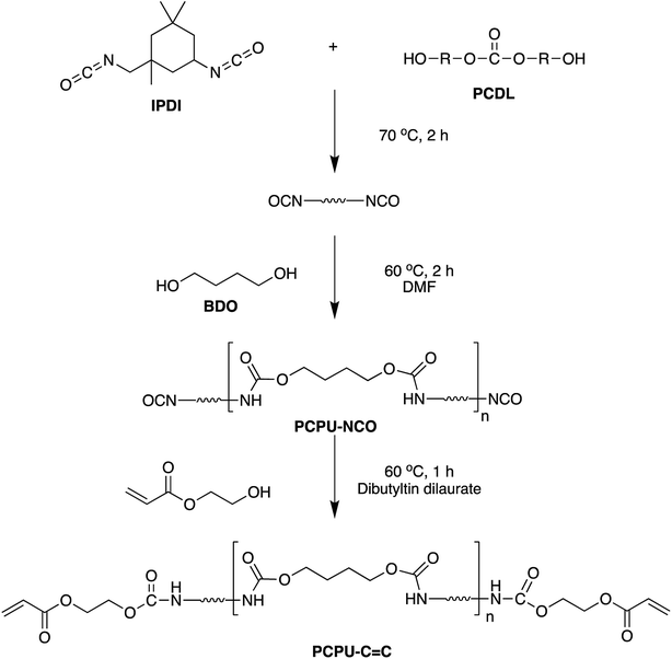
Scheme 1 shows the synthetic route of PCPU. Polycarbonate diol (PCDL, 1.8 g) and isophorone diisocyanate (IPDI, 4.45 g) were mixed in a flask, and reacted at 70 °C for 2 hours. The solution was then cooled down to 60 °C, and 1,4-butanediol (1.13 g) and DMF (10 mL) were added into the solution. The mixture was stirred at 60 °C for 2 hours, and yielded PCPU with the end group of isocyanate group (PCPU–NCO). Then, 2-hydroxyethyl acrylate (HEA, 1.60 g) and dibutyltin dilaurate (0.04 g) were added into the mixture. The mixture was stirred at 60 °C for another hour to obtain PCPU with carbon–carbon double bonds at the end of the polymer chain (PCPU–C![[double bond, length as m-dash]](https://www.rsc.org/images/entities/char_e001.gif) C).
C).
2.3. Preparation hydrophilic polycarbonate polyurethane (HPCPU) coated mesh
Scheme 2 shows the preparation of HPCPU-coated mesh. A steel-mesh (5 × 5 cm2, 300 mesh) was first cleaned with water and ethanol thoroughly, and dried. Then, the PCPU (2 mL) and DMF (6 mL) were mixed in a beaker. The steel-mesh was immersed into the solution for 10 seconds. The PCPU-coated mesh was obtained by drying the mesh at 70 °C for 30 minutes. Afterwards, the PCPU-coated mesh was immersed in an aqueous solution of APS (0.5 mg mL−1, 40 mL) at 70 °C for 10 minutes. Then, HEA (1.5 g) was added into the solution, and the mesh was kept in the solution for 6 hours at 70 °C to obtain HPCPU-coated mesh.2.4. Characterization
The chemical compositions of PCPU–CNO and PCPU–C![[double bond, length as m-dash]](https://www.rsc.org/images/entities/char_e001.gif) C were examined by Fourier transform infrared spectroscopy (FTIR, Prestige-21, Shimadzu, Japan). The HPCPU-coated mesh was investigated by thermal gravimetric analyzer (TG-STA7300, Hitachi, Japan). The morphology of the steel-mesh, PCPU-coated mesh, and HPCPU-coated mesh were characterized by scanning electron microscopy (SEM-TM3030, Hitachi, Japan). Underwater oleophobicity of the PCPU-coated mesh and the HPCPU-coated mesh was characterized by contact angle measurements (JJ2000B, Zhongchen, Shanghai, China) at room temperature. The measurements were carried out at minimum five positions.
C were examined by Fourier transform infrared spectroscopy (FTIR, Prestige-21, Shimadzu, Japan). The HPCPU-coated mesh was investigated by thermal gravimetric analyzer (TG-STA7300, Hitachi, Japan). The morphology of the steel-mesh, PCPU-coated mesh, and HPCPU-coated mesh were characterized by scanning electron microscopy (SEM-TM3030, Hitachi, Japan). Underwater oleophobicity of the PCPU-coated mesh and the HPCPU-coated mesh was characterized by contact angle measurements (JJ2000B, Zhongchen, Shanghai, China) at room temperature. The measurements were carried out at minimum five positions.
3. Results
3.1. FT-IR characterization of PCPU–CNO and PCPU–C![[double bond, length as m-dash]](https://www.rsc.org/images/entities/h3_char_e001.gif) C
C
In the synthesis, the introduction of C![[double bond, length as m-dash]](https://www.rsc.org/images/entities/char_e001.gif) C to PU is essential to achieve a stable and hydrophilic coating since the C
C to PU is essential to achieve a stable and hydrophilic coating since the C![[double bond, length as m-dash]](https://www.rsc.org/images/entities/char_e001.gif) C bonds can be easily crosslinked with HEA by free-radical polymerization. This process was characterized by FT-IR. The FT-IR spectra of PCPU–CNO and PCPU–C
C bonds can be easily crosslinked with HEA by free-radical polymerization. This process was characterized by FT-IR. The FT-IR spectra of PCPU–CNO and PCPU–C![[double bond, length as m-dash]](https://www.rsc.org/images/entities/char_e001.gif) C are shown in Fig. 1a. For the PCPU–NCO and PCPU–C
C are shown in Fig. 1a. For the PCPU–NCO and PCPU–C![[double bond, length as m-dash]](https://www.rsc.org/images/entities/char_e001.gif) C, the characteristic adsorptions are identified as follows: stretching vibrational absorption of secondary amino groups (–NH) of carbamate groups (–HNCOO–) at 3327 cm−1; methylene (–CH2–) at 2950 cm−1; carbonyl groups (–C
C, the characteristic adsorptions are identified as follows: stretching vibrational absorption of secondary amino groups (–NH) of carbamate groups (–HNCOO–) at 3327 cm−1; methylene (–CH2–) at 2950 cm−1; carbonyl groups (–C![[double bond, length as m-dash]](https://www.rsc.org/images/entities/char_e001.gif) O) of carbamate groups (–HNCOO–) at 1718 cm−1; ether groups (–C–O–) of carbamate groups (–HNCOO–) at 1250 cm−1; deformed vibrational absorption peak of secondary amino groups (–NH) of carbamate groups (–HNCOO–) at 1535 cm−1. In addition, for the PCPU–CNO, a sharp –NCO absorption peak is present at 2267 cm−1, and after the last step in the synthesis, the absorption peak at 2267 cm−1 was completely disappeared for the PCPU–C
O) of carbamate groups (–HNCOO–) at 1718 cm−1; ether groups (–C–O–) of carbamate groups (–HNCOO–) at 1250 cm−1; deformed vibrational absorption peak of secondary amino groups (–NH) of carbamate groups (–HNCOO–) at 1535 cm−1. In addition, for the PCPU–CNO, a sharp –NCO absorption peak is present at 2267 cm−1, and after the last step in the synthesis, the absorption peak at 2267 cm−1 was completely disappeared for the PCPU–C![[double bond, length as m-dash]](https://www.rsc.org/images/entities/char_e001.gif) C, indicating that the HEA successfully reacted with PCPC–CNO, which further resulted a HPCPU-coated mesh with superhydrophilicity and underwater superoleophobicity.
C, indicating that the HEA successfully reacted with PCPC–CNO, which further resulted a HPCPU-coated mesh with superhydrophilicity and underwater superoleophobicity.
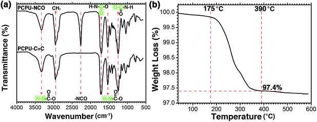 | ||
Fig. 1 (a) The FT-IR spectra of PCPU–CNO and PCPU–C![[double bond, length as m-dash]](https://www.rsc.org/images/entities/char_e001.gif) C. (b) Thermogravimetric analysis of the HPCPU-coated mesh. C. (b) Thermogravimetric analysis of the HPCPU-coated mesh. | ||
3.2. Thermogravimetric analysis of the HPCPU coated mesh
Because the coating will affect the flux as well as the preparation cost, HPCPU on the coated mesh was investigated by thermogravimetric analysis. As shown in Fig. 1b, the weight of the coated mesh started decreasing at 175 °C. When temperature reached 390 °C, the weight of coated mesh decreased to 97.4%, and leveled out, suggesting that the quality of coating accounts for 2.6% of the quality of the coated mesh.3.3. Mesh morphology
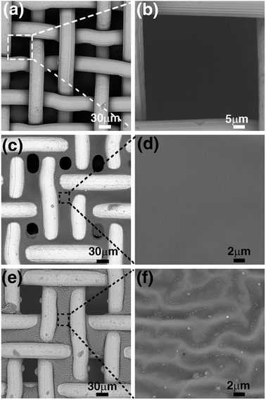
Fig. 2 shows the SEM images of the untreated steel-mesh, the PCPU-coated mesh, and the HPCPU-coated mesh. The untreated mesh shows a smooth surface of steel material (Fig. 2a), and the size of mesh is around 50 μm (Fig. 2b). The untreated mesh was simply dipped in the solution of PCPU for ten seconds, and left for drying. Due to the high viscosity of the solution, a fine layer of PCPU was covered on the steel mesh and formed a uniform film (Fig. 2c). The enlarged image of the film shows a smooth feature of the PCPU coated on the mesh (Fig. 2d). Small holes on the scale of 30 μm can be found on the mesh. The coating in the first step is a physical one in nature. The coated layer is dependent on the viscosity of the PCPU, and the coated layer may not be stable. In the synthesis, the reactive double bonds were introduced in the last step (Scheme 1). The acrylate group in PCPU can be easily crosslinked with HEA by free-radical polymerization to obtain two layer of coating HPCPU-coated mesh. Besides obtaining the hydrophilicity, the chemically crosslinked film is much more robust as it shows in the later tests. The surface of the PCPU-coated mesh is also undergone a noticeable change (Fig. 2d). Comparing to the PCPU-coated mesh, the HPCPU-coated mesh shows evenly distributed pores with the size of 50 μm (Fig. 2e). The enlarged view of the HPCPU surface displays a rough feature (Fig. 2f). Micrometer-scaled groove patterns formed on the surface of the HPCPU-coated mesh.3.4. The wettability of the PCPU and HPCPU-coated meshes
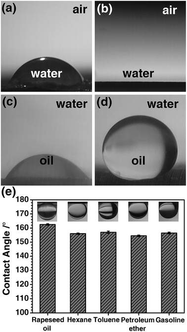
Chemical composition and the micro/nano-structure of a solid surface are the two factors that affect the wettability, and the wettability will further affect the separation efficiency of oil/water mixture. Thus, the wettability of the PCPU and HPCPU-coated meshes were characterized by the contact angle measurements (Fig. 3). In air, a droplet of water placed on the surface of the PCPU-coated mesh (Fig. 3a). The contact angle is about 60°. Whereas, the contact angle of water on the HPCPU-coated mesh is 0° (Fig. 3b). Under water, a droplet of dichloromethane placed on the surface of the PCPU-coated mesh (Fig. 3c). The contact angle is about 45°, indicating the PCPU-coated mesh can be wetted by oil (dichloromethane); whereas, the HPCPU-coated mesh shows an underwater superoleophobic feature because the contact angle of water/dichloromethane on the HPCPU-coated surface is larger than 150° (Fig. 3d). These results indicate that the PCPU-coated mesh was successfully modified and the surface of the mesh was the superhydrophilic and underwater superoleophobic.We further measured the contact angles of light oils/water beneath the surface of the HPCPU-coated mesh (Fig. 3e). In all the measurements, the contact angles are in the range of 154° to 162.5°, indicating the underwater superoleophobic feature of the HPCPU-coated mesh. This underwater superoleophobic feature can be attribute to the cooperative effect of the hydrophilicity of the massive hydroxyl groups on the grated poly-HEA and the rough microstructure of the coating (Fig. 2f). Due to this cooperative effect, water can be trapped in the rough microstructure and forms a hydrophilic layer, which provides a strong repulsive force to oil due to the difference of the surface tension. As a consequence, the coating material can also provide a barrier from oil stains, thus, prolonging its service life.
Subsequently, the adhesion of underwater oil on the surface of the HPCPU-coated mesh was also studied. The process of adhesion of dichloromethane oil on HPCPU-coated mesh was recorded (Fig. 4). In the first two steps, the needle was slowly moved towards the HPCPU-coated mesh. In the second picture, the dichloromethane contact with the HPCPU-mesh. When we retrieved the needle, the liquid drop was easily detached from the surface of the mesh. Based on this results, we may conclude the HPCPU-coated mesh has excellent resistance from oil contamination.
3.5. Oil/water separation
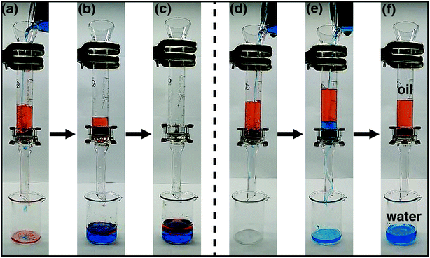
To test the capability of oil/water separation for the coated meshes, we carried out a series of proof-of-concept studies. The apparatus is shown in Fig. 5. The pre-wetted mesh was fixed between two volumetric cylinders. Mixture of n-hexane and water (1![[thin space (1/6-em)]](https://www.rsc.org/images/entities/char_2009.gif) :
:![[thin space (1/6-em)]](https://www.rsc.org/images/entities/char_2009.gif) 1 v/v) was poured in the cylinder. Fig. 5a–c show the process of oil/water separation for the PCPU-coated mesh. Both water and hexane quickly permeated through the mesh and dropped into a beaker (Video S1 in the ESI†). However, the oil/water separation by using the HPCPU-coated mesh exhibited a completely different scenario (Fig. 5d–f, and Video S2 in the ESI†). In Fig. 5f, water permeated through the mesh, whereas hexane retained above the mesh due to the superhydrophilic and underwater superoleophobic features of the coated mesh. Based on the visual inspection, no oil drop was found in the beaker, indicating high separation efficiency.
1 v/v) was poured in the cylinder. Fig. 5a–c show the process of oil/water separation for the PCPU-coated mesh. Both water and hexane quickly permeated through the mesh and dropped into a beaker (Video S1 in the ESI†). However, the oil/water separation by using the HPCPU-coated mesh exhibited a completely different scenario (Fig. 5d–f, and Video S2 in the ESI†). In Fig. 5f, water permeated through the mesh, whereas hexane retained above the mesh due to the superhydrophilic and underwater superoleophobic features of the coated mesh. Based on the visual inspection, no oil drop was found in the beaker, indicating high separation efficiency.
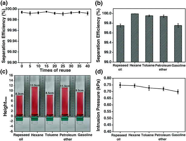
The reuse of the HPCPU-coated mesh (Fig. 6a) and a variety of oils (Fig. 6b) were tested for the oil/water separation by using the HPCPU-coated mesh. The separation efficiency (η) can be quantitatively calculated as follows:  , where m1 and m2 are the mass of oil in water before and after the separation, respectively. The separation efficiency for the hexane/water system was 99.994% on the first separation, and maintained on the very high level after even 40 separation cycles (Fig. 6a). We further evaluated the durability of the mesh on the oil/water separation. After 500 cycles of oil/water separation, the separation efficiency retained above 99.7% the separation efficiency. Fig. 6b shows the separation efficiency for the oil/water mixtures of other five types of oil. The separation efficiencies are all higher than 99.7%.
The intrusion pressure of the oils on the HPCPU-coated mesh is a parameter that assesses the separation ability of coated meshes. Based on the definition: P = ρghmax, the experimental intrusion pressure of the oils on the HPCPU-coated mesh was calculated, where ρ is the density of the oil, g is the acceleration of gravity and hmax is the maximum height of the oil that the coated mesh can support. The average maximum heights of 5 measurements for a series of oil are obtained, and all of them are higher than 8 cm (Fig. 6c). Correspondingly, the experimental intrusion pressure is calculated to be over 0.7 kPa (Fig. 6d).
In addition to the separation efficiency and the intrusion pressure, the flux per unit time is also important. The flux of liquid (F) is investigated as follows:  where V is the volume of liquid permeated through the mesh, r is the radius of the cylinder, and t is the time taking for the permeation of V mL liquid. In the measurements, 0.5 L water was used to evaluate the flux, and the average value of flux is around 25 L m−2 s−1.
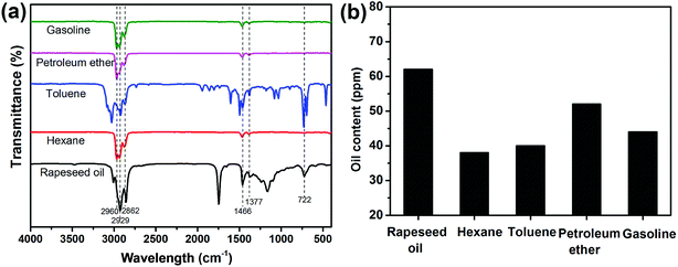
The purity of the collected oils (rapeseed oil, hexane, toluene, petroleum ether and gasoline) was investigated by FTIR (Fig. 7a). All the absorption bands were owing to the characteristic vibrations of the chemical constituents of the collected oils. The bands from 2862 to 2960 cm−1 were assigned to the –C–H asymmetric and symmetric stretching vibration of –CH3 and –CH2– groups. The –C–H scissoring vibration of –CH2– groups and the –C–H asymmetric stretching vibration of –CH3 groups were found at 1466 cm−1. The bands at 1377 cm−1 corresponded to the –C–H symmetric bending vibration of –CH3 groups. The bands around 722 cm−1 originated from the –(CH2)n– rocking vibration and –HC![[double bond, length as m-dash]](https://www.rsc.org/images/entities/char_e001.gif) CH– bending vibration. No trace of water was observed based on FTIR spectra, implying the high purity of the separated oils. In addition, the amount of oil in the collected water was evaluated (see Fig. 7b). According to the results, the oil content was lower than 65 ppm for the four oil/water mixtures. Therefore, the HPCPU-coated mesh is highly efficient for oil/water separation.
CH– bending vibration. No trace of water was observed based on FTIR spectra, implying the high purity of the separated oils. In addition, the amount of oil in the collected water was evaluated (see Fig. 7b). According to the results, the oil content was lower than 65 ppm for the four oil/water mixtures. Therefore, the HPCPU-coated mesh is highly efficient for oil/water separation.
3.6. The effect of synthetic conditions on oil/water separation
As aforementioned, chemical composition and the micro/nano-structure of the mesh affect the oil/water separation. These two factors change with the reaction conditions. Therefore, we investigated the effects of three reaction conditions on the separation efficiency, flux and intrusion pressure, which are the concentration of PCPU in DMF, the amount of HEA added as the reactant, and the reaction time.The viscosity of PCPU is dependent on the concentration. With less PCPU in DMF, the solution becomes less viscous. In this case, when dip the mesh in the PCPU solution, there will be less PCPU coated on the mesh, and further affects the oil/water separation. In the experiment, we fix the amount of PCPU (2 mL) added into DMF, and increase the amount of DMF from 2 to 8 mL, corresponding to the concentration of PCPU in the region of 8.8 to 22.8 wt%. The amount of HEA (1 g) and reaction time (10 h) were kept constant. We observed that the flux substantially increased with the decrease of the concentration of PCPU (Fig. 8a). However, the separation efficiency remained unchanged when the concentration of PCPU was above 11 wt%. The decrease of separation efficiency may suggest the coating on the mesh is not enough, and therefore jeopardize the oil/water separation. Another interesting observation in Fig. 8a is that the separation efficiency shows a good correlation to the intrusion pressure. This argument will be further strengthened based on the results in Fig. 8b and c.
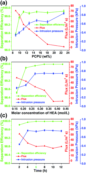 | ||
| Fig. 8 The effects of (a) PCPU concentration, (b) HEA concentration, and (c) reaction time on flux, separation efficiency, and intrusion pressure. | ||
The addition of HEA will finally crosslink the PCPU chains in the coating, which contributes to the stability of the coating as well as the separation efficiency. The PCPU concentration was kept as 11.1% and the reaction time as 10 hours, and changed the amount of HEA in the reaction from 0.75 to 2 g (corresponding to 0.16 to 0.43 mol L−1). A monotonic decrease of flux was observed with increasing HEA concentration in the reaction. While, the separation efficiency and intrusion pressure are both increased when HEA concentration is below 0.27 mol L−1, and afterwards levels off.
Based on these two results (Fig. 8a and b), we studied the effect of the reaction time on the oil/water separation. The results (Fig. 8c) show that reaction time has very little effect on the oil/water separation providing the enough reaction time (>2 hours) is given. This result is reasonable for the reaction rate of free-radical polymerization is generally large.
3.7. Stability of the HPCPU-coated mesh in various environments
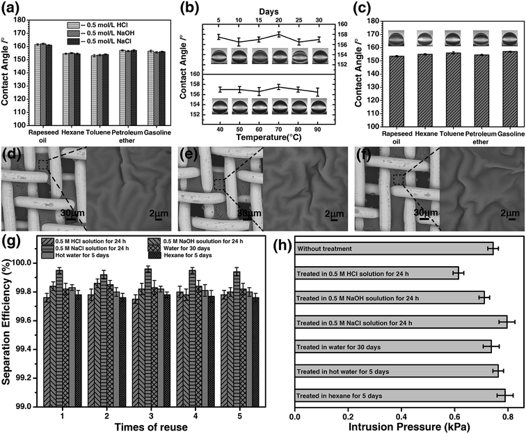
The stability of the coated materials was investigated in harsh environments. The meshes were pretreated with 0.5 M HCl solution, 0.5 M NaOH solution, and 0.5 M NaCl solution for 24 hours. Afterwards, the meshes were used to separate the hexane/water mixture. The results are presented in Fig. 9. After the treatments, the underwater contact angle was first measured for the meshes, and Fig. 9a shows the contact angle of five types of oils on the mesh after being pretreatment. The contact angles remained the same for all types of oils, and little difference was observed for the meshes being pretreated in acidic, basic or saline solutions. The microstructure of mesh was examined by SEM. Based on the contact angle and SEM image (Fig. 9d), we conclude that the microstructure of the coated mesh is very stable in acidic, basic, and saline solutions. The separation of hexane/water mixture was performed with the meshes immersed in the solutions, respectively. Water passes through the mesh, whereas, hexane was stopped by the mesh and retained on the upper tube. The separation efficiency of the mesh was up to 99.7% for the three meshes treated with the acidic, basic, and salt solutions (Fig. 9g). The intrusion pressure after the treatments is also maintained on the same level as it was for the original mesh (Fig. 9h).Considering that the materials used to separate oil/water should sustain in mal conditions for practical applications, we investigated the durability of the HPCPU-coated mesh. After the mesh being immersed in water for 30 days successively, the separation of hexane/water mixture was studied. The underwater contact angle of dichloromethane remained nearly the same during the 30 days (Fig. 9b). In addition, we tested the endurance of the mesh in hot water at different temperatures for 5 days. The contact angle after the hot-water treatment is presented in Fig. 9b. We conclude that the mesh is also durable in hot water. The microstructure of the mesh also remained the same as original (Fig. 9e). We tested the separation efficiency and intrusion pressure after these two treatments. The reuse of the mesh was tested for 5 times, and the separation efficiency is higher than 99.8% (Fig. 9g). The intrusion pressure also maintained on the same level as original (Fig. 9h).
Many of materials with underwater superoleophobicity were obtained by coating hydrophilic materials on a mesh. However, as shown in Scheme 3a, due to the superhydrophilic property of the coating and lacking covalent bonds between the matrix and the coating materials, the coating easily falls off from the mesh after being in water for long time so that the separation ability of the mesh is damaged. Here, chemically processed PCPU–C![[double bond, length as m-dash]](https://www.rsc.org/images/entities/char_e001.gif) C with the properties of water resistant and heat-resistant as inner layer was first coated on the stainless steel mesh, and then PHEA as outer layer was grafted on the PCPU-coated mesh by free-radical polymerization. As shown in Scheme 3b, because the inner layer (PCPU) is water resistant, heat-resistant and adheres strongly to the stainless steel mesh, in addition, the outer layer (PHEA) is chemically crosslinked with the inner layer, the as-prepared two layer of coating shows excellent long-term stability in water, and even hot water.
C with the properties of water resistant and heat-resistant as inner layer was first coated on the stainless steel mesh, and then PHEA as outer layer was grafted on the PCPU-coated mesh by free-radical polymerization. As shown in Scheme 3b, because the inner layer (PCPU) is water resistant, heat-resistant and adheres strongly to the stainless steel mesh, in addition, the outer layer (PHEA) is chemically crosslinked with the inner layer, the as-prepared two layer of coating shows excellent long-term stability in water, and even hot water.
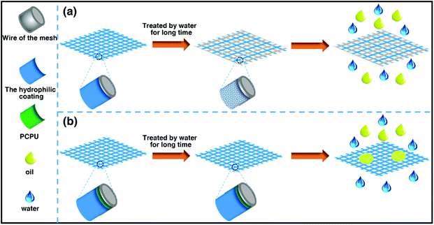 | ||
| Scheme 3 A demonstration of traditional materials with underwater superoleophobicity and materials we prepared in water for long term application. | ||
Moreover, we tested the fouling resistance of the HPCPU-coated meshes. The mesh used in the experiment was treated in different oils (rapeseed oil, hexane, gasoline, toluene, and petroleum ether) for 5 days. The underwater contact angle of dichloromethane remains higher than 150° (Fig. 9c). The SEM image shows that the microstructure of the mesh remains the same (Fig. 9f). The separation efficiency and intrusion pressure presented in Fig. 9g and h show that after pre-soaked in oil for 5 days the HPCPU-coated mesh still exhibits very high separation efficiency and the same intrusion pressure. The strong endurance of the HPCPU-coated mesh provides the possibility of using the mesh for water/oil separation in industrial scale.
4. Conclusions
We have successfully synthesized the superhydrophilic and underwater superoleophobic HPCPU-coated mesh, which exhibits excellent water/oil separation capacity. The HPCPU-coated mesh was tested to separate water from the various water/oil mixtures with excellent separation efficiency. Here, we want to emphasize the durability and the fouling resistance of HPCPU. When the mesh was pre-treated with the acidic, alkaline, and salt solutions, the separation efficiency was kept up to 99.7%. When the mesh was treated with hot water and pre-soaked in various oils, the separation efficiency maintained on the same level. With such property, the HPCPU-coated mesh could be used in very harsh environments, and real application in industrial scale.Conflicts of interest
There are no conflicts to declare.Acknowledgements
We thank the Natural Science Foundation of Xinjiang Uyghur Autonomous Region (2016D01C037).References
- B. M. Jenssen, Environ. Pollut., 1994, 86, 207–215 CrossRef CAS PubMed.
- M. Cheryan and N. Rajagopalan, J. Membr. Sci., 1998, 151, 13–28 CrossRef CAS.
- M. A. Shannon, P. W. Bohn, M. Elimelech, J. G. Georgiadis, B. J. Marinas and A. M. Mayes, Nature, 2008, 452, 301–310 CrossRef CAS PubMed.
- Q. Ma, H. Cheng, A. G. Fane, R. Wang and H. Zhang, Small, 2016, 12, 2186–2202 CrossRef CAS PubMed.
- Z. Chu, Y. Feng and S. Seeger, Angew. Chem., Int. Ed., 2015, 54, 2328–2338 CrossRef CAS PubMed.
- X. Gao, L.-P. Xu, Z. Xue, L. Feng, J. Peng, Y. Wen, S. Wang and X. Zhang, Adv. Mater., 2014, 26, 1771–1775 CrossRef CAS PubMed.
- R. Boopathy, S. Shields and S. Nunna, Appl. Biochem. Biotechnol., 2012, 167, 1560–1568 CrossRef CAS PubMed.
- V. Broje and A. A. Keller, Environ. Sci. Technol., 2006, 40, 7914–7918 CrossRef CAS PubMed.
- M. O. Adebajo, R. L. Frost, J. T. Kloprogge, O. Carmody and S. Kokot, J. Porous Mater., 2003, 10, 159–170 CrossRef CAS.
- J. Chen, H. You, L. Xu, T. Li, X. Jiang and C. M. Li, J. Colloid Interface Sci., 2017, 506, 659–668 CrossRef CAS PubMed.
- F. Beshkar, H. Khojasteh and M. Salavati-Niasari, J. Colloid Interface Sci., 2017, 497, 57–65 CrossRef CAS PubMed.
- L. Feng, Z. Y. Zhang, Z. H. Mai, Y. M. Ma, B. Q. Liu, L. Jiang and D. B. Zhu, Angew. Chem., Int. Ed., 2004, 43, 2012–2014 CrossRef CAS PubMed.
- Z. J. Cheng, H. W. Liu, H. Lai, Y. Du, K. W. Fu, C. Li, J. X. Yu, N. Q. Zhang and K. N. Sun, ACS Appl. Mater. Interfaces, 2015, 7, 20410–20417 CrossRef CAS PubMed.
- F. J. Wang, S. Lei, C. Q. Li, J. F. Ou, M. S. Xue and W. Li, Ind. Eng. Chem. Res., 2014, 53, 7141–7148 CrossRef CAS.
- X. Zhu, Z. Zhang, B. Ge, X. Men, X. Zhou and Q. Xue, J. Colloid Interface Sci., 2014, 432, 105–108 CrossRef CAS PubMed.
- L. Zhang, L. Li and Z.-M. Dang, J. Colloid Interface Sci., 2016, 463, 266–271 CrossRef CAS PubMed.
- S. Yang, L. Chen, C. Wang, M. Rana and P.-C. Ma, J. Colloid Interface Sci., 2017, 508, 254–262 CrossRef CAS PubMed.
- B. Shang, Y. Wang, B. Peng and Z. Deng, J. Colloid Interface Sci., 2016, 482, 240–251 CrossRef CAS PubMed.
- D. Li and Z. Guo, J. Colloid Interface Sci., 2017, 503, 124–130 CrossRef CAS PubMed.
- H. Zhu, L. Gao, X. Yu, C. Liang and Y. Zhang, Appl. Surf. Sci., 2017, 407, 145–155 CrossRef CAS.
- W. Zhou, G. Li, L. Wang, Z. Chen and Y. Lin, Appl. Surf. Sci., 2017, 413, 140–148 CrossRef CAS.
- J. Yang, H. J. Song, X. H. Yan, H. Tang and C. S. Li, Cellulose, 2014, 21, 1851–1857 CrossRef CAS.
- J. Yang, Z. Z. Zhang, X. H. Xu, X. T. Zhu, X. H. Men and X. Y. Zhou, J. Mater. Chem., 2012, 22, 2834–2837 RSC.
- J. Yang, L. T. Yin, H. Tang, H. J. Song, X. N. Gao, K. Liang and C. S. Li, Chem. Eng. J., 2015, 268, 245–250 CrossRef CAS.
- N. Valipour Motlagh, F. C. Birjandi, J. Sargolzaei and N. Shahtahmassebi, Appl. Surf. Sci., 2013, 283, 636–647 CrossRef CAS.
- H. Yu, Z. Lian, J. Xu, Y. Wan, Z. Wang, Y. Li, Z. Yu and Z. Weng, Appl. Surf. Sci., 2017, 437, 400–409 CrossRef.
- Q. Wang, Y. Fu, X. Yan, Y. Chang, L. Ren and J. Zhou, Appl. Surf. Sci., 2017, 412, 10–18 CrossRef CAS.
- K. Hou, Y. Zeng, C. Zhou, J. Chen, X. Wen, S. Xu, J. Cheng, Y. Lin and P. Pi, Appl. Surf. Sci., 2017, 416, 344–352 CrossRef CAS.
- J. Li, R. Kang, X. Tang, H. She, Y. Yang and F. Zha, Nanoscale, 2016, 8, 7638–7645 RSC.
- J. Li, L. Yan, H. Li, W. Li, F. Zha and Z. Lei, J. Mater. Chem. A, 2015, 3, 14696–14702 RSC.
- J. Li, D. Li, Y. Yang, J. Li, F. Zha and Z. Lei, Green Chem., 2016, 18, 541–549 RSC.
- J. Li, C. Xu, C. Guo, H. Tian, F. Zha and L. Guo, J. Mater. Chem. A, 2018, 6, 223–230 RSC.
- Z. Xu, Y. Zhao, H. Wang, H. Zhou, C. Qin, X. Wang and T. Lin, ACS Appl. Mater. Interfaces, 2016, 8, 5661–5667 CrossRef CAS PubMed.
- X. Zheng, Z. Guo, D. Tian, X. Zhang, W. Li and L. Jiang, ACS Appl. Mater. Interfaces, 2015, 7, 4336–4343 CrossRef CAS PubMed.
- X. Zhou, Z. Zhang, X. Xu, F. Guo, X. Zhu, X. Men and B. Ge, ACS Appl. Mater. Interfaces, 2013, 5, 7208–7214 CrossRef CAS PubMed.
- Z.-Y. Luo, K.-X. Chen, J.-H. Wang, D.-C. Mo and S.-S. Lyu, J. Mater. Chem. A, 2016, 4, 10566–10574 RSC.
- F. Chen, J. L. Song, Z. Liu, J. Y. Liu, H. X. Zheng, S. Huang, J. Sun, W. J. Xu and X. Liu, ACS Sustainable Chem. Eng., 2016, 4, 6828–6837 CrossRef CAS.
- H. L. Peng, J. N. Wu, Y. X. Wang, H. Wang, Z. Y. Liu, Y. L. Shi and X. H. Guo, Appl. Phys. A: Mater. Sci. Process., 2016, 122, 516 CrossRef.
- Z. Xu, Y. Zhao, H. Wang, X. Wang and T. Lin, Angew. Chem., Int. Ed., 2015, 54, 4527–4530 CrossRef CAS PubMed.
- X. Chen, J. A. Weibel and S. V. Garimella, Ind. Eng. Chem. Res., 2016, 55, 3596–3602 CrossRef CAS.
- L. Li, L. Liu, J. Lei, J. He, N. Li and F. Pan, J. Mater. Chem. A, 2016, 4, 12334–12340 RSC.
- Y. Cao, N. Liu, W. Zhang, L. Feng and Y. Wei, ACS Appl. Mater. Interfaces, 2016, 8, 3333–3339 CrossRef CAS PubMed.
- Z. X. Xue, S. T. Wang, L. Lin, L. Chen, M. J. Liu, L. Feng and L. Jiang, Adv. Mater., 2011, 23, 4270–4273 CrossRef CAS PubMed.
- Y. Q. Liu, Y. L. Zhang, X. Y. Fu and H. B. Sun, ACS Appl. Mater. Interfaces, 2015, 7, 20930–20936 CrossRef CAS PubMed.
- Y. Dong, J. Li, L. Shi, X. B. Wang, Z. G. Guo and W. M. Liu, Chem. Commun., 2014, 50, 5586–5589 RSC.
- Z.-Q. Dong, B.-J. Wang, M. Liu, X.-h. Ma and Z.-L. Xu, RSC Adv., 2016, 6, 65171–65178 RSC.
- J. Li, L. Yan, W. Li, J. Li, F. Zha and Z. Lei, Mater. Lett., 2015, 153, 62–65 CrossRef CAS.
- S. Zhang, F. Lu, L. Tao, N. Liu, C. Gao, L. Feng and Y. Wei, ACS Appl. Mater. Interfaces, 2013, 5, 11971–11976 CrossRef CAS PubMed.
- Z. Cheng, H. Lai, Y. Du, K. Fu, R. Hou, C. Li, N. Zhang and K. Sun, ACS Appl. Mater. Interfaces, 2014, 6, 636–641 CrossRef CAS PubMed.
- N. Liu, Y. Cao, X. Lin, Y. Chen, L. Feng and Y. Wei, ACS Appl. Mater. Interfaces, 2014, 6, 12821–12826 CrossRef CAS PubMed.
- F. Zhang, W. B. Zhang, Z. Shi, D. Wang, J. Jin and L. Jiang, Adv. Mater., 2013, 25, 4192–4198 CrossRef CAS PubMed.
- S. Yanlong, Y. Wu, F. Xiaojuan, W. Yongsheng, Y. Guoren and J. Shuping, Appl. Surf. Sci., 2016, 367, 493–499 CrossRef.
- Y. Zhang, W. Li, R. Wu and W. Wang, RSC Adv., 2017, 7, 33701–33707 RSC.
- W. Li, X. Jiang, R. Wu and W. Wang, Polym. J., 2017, 49, 263–271 CrossRef CAS.
- Y. Zhang, X. Jiang, R. Wu and W. Wang, J. Appl. Polym. Sci., 2016, 133, 43534 Search PubMed.
- Z. Wang, W. Li, X. Yang, J. Cao, Y. Tu, R. Wu and W. Wang, Mater. Today Commun., 2018, 17, 246–251 CrossRef.
Footnote |
| † Electronic supplementary information (ESI) available: The videos for oil/water separations are available in the supporting information. See DOI: 10.1039/c8ra07965j |
| This journal is © The Royal Society of Chemistry 2018 |

