 Open Access Article
Controllable synthesis of nanostructured ZnCo2O4 as high-performance anode materials for lithium-ion batteries†
Huan Liu,
Xinlu Wang *,
Hang Xu,
Jinxian Wang
 *,
Qianli Ma,
Wensheng Yu,
Ying Yang
 ,
Xiangting Dong
 ,
Guixia Liu
 and
Yan Zhao
Key Laboratory of Applied Chemistry and Nanotechnology at Universities of Jilin Province, Department of Chemistry & Environmental Engineering, Changchun University of Science and Technology, Changchun, Jilin 130022, PR China. E-mail: xinluwang@163.com; wjx87@sina.com
First published on 26th November 2018
Abstract
Nanostructured ZnCo2O4 anode materials for lithium-ion batteries (LIBs) have been successfully prepared by a two-step process, combining facile and concise electrospinning and simple post-treatment techniques. Three different structured ZnCo2O4 anodes (nanoparticles, nanotubes and nanowires) can be prepared by simply adjusting the ratio of metallic salt and PVP in the precursor solutions. Charge–discharge tests and cyclic voltammetry (CV) have been conducted to evaluate the lithium storage performances of ZnCo2O4 anodes, particularly for ZnCo2O4 nanotubes obtained from a weight ratio 2![[thin space (1/6-em)]](https://www.rsc.org/images/entities/char_2009.gif) :
:![[thin space (1/6-em)]](https://www.rsc.org/images/entities/char_2009.gif) 4 of metallic salt and PVP polymer in the precursor solution. Remarkably, ZnCo2O4 nanotubes exhibit high specific capacity, good rate property, and long cycling stability. Reversible capacity is still maintained at 1180.8 mA h g−1 after 275 cycles at a current density of 200 mA g−1. In case of rate capability, even after cycling at the 2000 mA g−1 current density, the capacity could recover to 684 mA h g−1. The brilliant electrochemical properties of the ZnCo2O4 anodes make them promising anodes for LIBs and other energy storage applications.
4 of metallic salt and PVP polymer in the precursor solution. Remarkably, ZnCo2O4 nanotubes exhibit high specific capacity, good rate property, and long cycling stability. Reversible capacity is still maintained at 1180.8 mA h g−1 after 275 cycles at a current density of 200 mA g−1. In case of rate capability, even after cycling at the 2000 mA g−1 current density, the capacity could recover to 684 mA h g−1. The brilliant electrochemical properties of the ZnCo2O4 anodes make them promising anodes for LIBs and other energy storage applications.
Introduction
Rechargeable lithium-ion batteries (LIBs) with high energy and power density, long cycle life and light weight have become one of the most promising power sources for future society due to their excellent performance in many renewable energy storage systems ranging from laptops and cellphones to hybrid electric vehicles (HEV).1–3 With the growing demand for higher capacity and safety, numerous efforts have been made to develop alternative next-generation LIBs with high volumetric energy density and gravimetric energy density.4–7 In the development of LIBs, one of the major challenges is to replace commercialized graphite anode material (theoretical specific capacity 372 mA h g−1) with higher capacity anode materials.8As promising anode materials, transition metal oxides (TMOs) have been used in place of graphite for LIBs.9,10 ZnCo2O4, a ternary oxide material, has been reported as a promising electrode material for LIBs.11–13 With a cubic spinel structure, ZnCo2O4 is isomorphic to Co3O4, i.e., Zn2+ ions occupy the tetrahedral sites and the Co3+ ions occupy the octahedral sites, revealing superior electroactivity to Co3O4.14 In addition, Zn element has many other advantages, including low cost, abundant resources and environment friendliness. It is well known that the large volume change associated with lithiation–delithiation of TMOs is a very common phenomenon, which can significantly impede the practical application of TMO-based anodes.15,16 Therefore, among many TMO-based anodes, ZnCo2O4 anode materials with novel structures, particularly specially fabricated nanostructures, have been often investigated as materials that accommodate the impact of volumetric change during the battery cycling process.17,18
Recently, much effort has been paid towards hybrid hetero-structured nanocomposites via rationally hybridizing metal oxides to enhance their lithium storage properties. The hierarchical materials enable characteristics of both nano- and micro-structures by vastly shortening the diffusion pathway as well as the kinetics of Li+ ions via a large surface area, contributing to high power and energy density.19–21 However, the reported synthesis methods have many limitations, including multi-step processes, high fabrication costs, poor reproducibility and employment of hazardous chemicals, which make the preparation procedure complicated and limit their large-scale applications.22–24 Designing a simple two-step strategy to synthesize uniquely structured high capacity anodes has been the biggest challenge. Electrospinning is a facile, scalable and low-cost method to produce continuous nanofibers and fibrous composites by applying a strong electric field between the nozzle tip and the collector while injecting a polymer solution.25–27 This method is very suitable for the preparation of one-dimensional (1D) structured TMOs as anode materials.28,29
Herein, we designed a fibrous structure to improve the electrochemical performance of ZnCo2O4 (denoted as ZCO) electrodes via a facile single-nozzle electrospinning approach and subsequent heat treatment without any additional steps. The structures of the final products of ZCO can be tuned by defining the weight ratio of nitrates and PVP polymer in the precursor polymeric solution. Electrochemical performances of the ZCO anodes were explored elaborately. These ZCO anode materials can achieve high coulombic efficiency (CE), respectable rate stability, reversible capacity, and long lifespan. Particularly, the 1D fibrous structure is composed of ZnCo2O4 nanoparticles (NPs). The unique fibrous structure can not only buffer the volume variation of ZnCo2O4 NPs, but also facilitate efficient electron transport and decrease Li+ ion diffusion distance. Our study may expand the promising routes to rationally design and fabricate novel ZnCo2O4-based materials with tunable structures for high capability in applications of power supply and energy conversion.
Experimental
Synthesis of ZCO
ZnCo2O4 nanofibers were fabricated by introducing a novel electrospinning technique. All chemical reagents were employed without any further purification. Polyvinylpyrrolidone (PVP, average Mw = 50 k, supplied by Aladdin) and N,N-dimethylformamide (DMF) solvent were used to prepare the polymer precursor solutions. After PVP was completely dissolved, stoichiometric amounts of Zn(NO3)2·6H2O (Aladdin) and Co(NO3)2·6H2O (Aladdin) with a Zn/Co molar ratio of 1![[thin space (1/6-em)]](https://www.rsc.org/images/entities/char_2009.gif) :
:![[thin space (1/6-em)]](https://www.rsc.org/images/entities/char_2009.gif) 2 were added to the polymer precursor solution under constant stirring. After the metal salts were added in the polymer precursor solution, the mixed precursor solution was agitated for six hours at ambient temperature to obtain a uniform solution. To investigate the influence of viscosity on the fibrous texture, three precursor solutions with different mass proportions of metal salts (marked as M) and PVP were determined before preparation. To effectively control the variables, weight of the metal salts was kept constant. The denoted samples were ZCO-1 with M
2 were added to the polymer precursor solution under constant stirring. After the metal salts were added in the polymer precursor solution, the mixed precursor solution was agitated for six hours at ambient temperature to obtain a uniform solution. To investigate the influence of viscosity on the fibrous texture, three precursor solutions with different mass proportions of metal salts (marked as M) and PVP were determined before preparation. To effectively control the variables, weight of the metal salts was kept constant. The denoted samples were ZCO-1 with M![[thin space (1/6-em)]](https://www.rsc.org/images/entities/char_2009.gif) :
:![[thin space (1/6-em)]](https://www.rsc.org/images/entities/char_2009.gif) PVP = 1
PVP = 1![[thin space (1/6-em)]](https://www.rsc.org/images/entities/char_2009.gif) :
:![[thin space (1/6-em)]](https://www.rsc.org/images/entities/char_2009.gif) 4, ZCO-2 with M
4, ZCO-2 with M![[thin space (1/6-em)]](https://www.rsc.org/images/entities/char_2009.gif) :
:![[thin space (1/6-em)]](https://www.rsc.org/images/entities/char_2009.gif) PVP = 2
PVP = 2![[thin space (1/6-em)]](https://www.rsc.org/images/entities/char_2009.gif) :
:![[thin space (1/6-em)]](https://www.rsc.org/images/entities/char_2009.gif) 4 and ZCO-3 with M
4 and ZCO-3 with M![[thin space (1/6-em)]](https://www.rsc.org/images/entities/char_2009.gif) :
:![[thin space (1/6-em)]](https://www.rsc.org/images/entities/char_2009.gif) PVP = 3
PVP = 3![[thin space (1/6-em)]](https://www.rsc.org/images/entities/char_2009.gif) :
:![[thin space (1/6-em)]](https://www.rsc.org/images/entities/char_2009.gif) 4. The mixed polymer solution was filled into a 12-gauge injection needle-plugged 10 mL syringe, and then accessed to a 12 kV high voltage circuit by extending to a DC power supply (Wendong High Voltage Power Supply for Research, Tianjin). For electrospinning, the high voltage cathode was connected to the needle tip while a low voltage anode of Al foil collector was kept 15 cm away. After the electrospinning process, the as-prepared precursor film was peeled off from the Al foil collector, and then stabilized in air at 250 °C for 2 h and followed by 500 °C for 4 h at a heating rate of 1 °C min−1 under air atmosphere of a tube furnace to produce the nanostructured ZnCo2O4.
4. The mixed polymer solution was filled into a 12-gauge injection needle-plugged 10 mL syringe, and then accessed to a 12 kV high voltage circuit by extending to a DC power supply (Wendong High Voltage Power Supply for Research, Tianjin). For electrospinning, the high voltage cathode was connected to the needle tip while a low voltage anode of Al foil collector was kept 15 cm away. After the electrospinning process, the as-prepared precursor film was peeled off from the Al foil collector, and then stabilized in air at 250 °C for 2 h and followed by 500 °C for 4 h at a heating rate of 1 °C min−1 under air atmosphere of a tube furnace to produce the nanostructured ZnCo2O4.
Structural characterization
Crystal structural characteristics were evaluated on a powder X-ray diffraction system (XRD, TD-3000, Tongda Co. Ltd., Dandong, Cu Kα, λ = 1.5418 Å). Morphologies of the selected products were observed using a field-emission scanning electron microscope (SEM, JEOL JSM-6710F, 10 kV). Transmission electron microscopy (TEM) and high-resolution TEM (HRTEM) (TEM, FEI Tecnai G2 S-Twin, 200 kV) were performed for analyzing the structures for the products. X-ray photoelectron spectroscopy (XPS, VG ESCALAB MKII, Al Kα) was used to analyze surface elemental properties of the as-prepared products.Electrochemical measurements
For the battery test, electrochemical performances of the fibrous ZnCo2O4 anodes were investigated in an electrolyte of 1 M LiPF6 in a mixture of ethylene carbonate and dimethyl carbonate (EC/DMC, 1![[thin space (1/6-em)]](https://www.rsc.org/images/entities/char_2009.gif) :
:![[thin space (1/6-em)]](https://www.rsc.org/images/entities/char_2009.gif) 1 vol%). A slurry composed of 70% ZnCo2O4, 20% carbon black and 10% polyvinylidene fluoride (PVDF) in N-methyl-2-pyrrolidone (NMP) was homogeneously pasted onto a Cu film and dried at 80 °C in a vacuum oven overnight. After the solvent was evaporated, the Cu flim was compressed and then stamped into round discs of 12 mm diameter and 1 mg cm−2 tap density. 2032-type half-coin batteries were assembled in an Ar-filled glovebox, containing moisture and oxygen limited to under 1 ppm, with Li foil as reference and counter electrode and the as-prepared fibrous ZnCo2O4 as the working electrode; the electrodes were separated by Celgard 2400 microporous polyethylene film. The coin cells were tested for cycling stability using a computer-controlled galvanostat (NEWARE BTS 5 V to 5 mA, Shenzhen) at an ambient condition with voltage window of 0.01–3.0 V and various current density steps ranging from 200 to 2000 mA g−1. Cyclic voltammetry (CV) tests from 0.01 to 3.0 V at a scan rate of 0.2 mV s−1 and electrochemical impedance spectrometry (EIS) tests in the frequency ranging from 0.01 to 100 kHz were performed on a CHI-760E Electrochemical Workstation at room temperature.
1 vol%). A slurry composed of 70% ZnCo2O4, 20% carbon black and 10% polyvinylidene fluoride (PVDF) in N-methyl-2-pyrrolidone (NMP) was homogeneously pasted onto a Cu film and dried at 80 °C in a vacuum oven overnight. After the solvent was evaporated, the Cu flim was compressed and then stamped into round discs of 12 mm diameter and 1 mg cm−2 tap density. 2032-type half-coin batteries were assembled in an Ar-filled glovebox, containing moisture and oxygen limited to under 1 ppm, with Li foil as reference and counter electrode and the as-prepared fibrous ZnCo2O4 as the working electrode; the electrodes were separated by Celgard 2400 microporous polyethylene film. The coin cells were tested for cycling stability using a computer-controlled galvanostat (NEWARE BTS 5 V to 5 mA, Shenzhen) at an ambient condition with voltage window of 0.01–3.0 V and various current density steps ranging from 200 to 2000 mA g−1. Cyclic voltammetry (CV) tests from 0.01 to 3.0 V at a scan rate of 0.2 mV s−1 and electrochemical impedance spectrometry (EIS) tests in the frequency ranging from 0.01 to 100 kHz were performed on a CHI-760E Electrochemical Workstation at room temperature.
Results and discussion
Phase purity and crystalline structures of the as-fabricated three ZnCo2O4 products were examined by powder X-ray diffraction (XRD), as shown in Fig. 1a. All of the identified diffraction peaks can be explicitly assigned to the ZnCo2O4 phase (JCPDS card no. 23-1390). No additional diffraction peaks for possible impurities are observed in the XRD patterns, demonstrating the purity of our synthesis approach. As described in Fig. 1a, the characteristic peak positions of the three obtained products shown in their diffraction patterns are nearly the same. The peaks ascribed to (111), (220), (311), (222), (400), (422), (511), (440), (620), and (533) planes can be apparently detected in the XRD pattern of the three products, reflecting the cubic spinel structure of ZnCo2O4.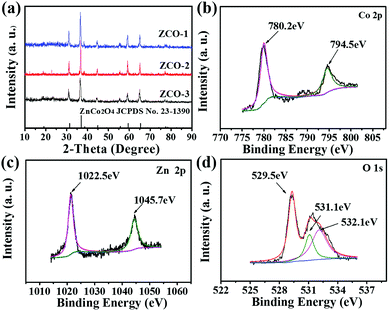 | ||
| Fig. 1 (a) XRD patterns for the as-fabricated three products. XPS spectra for the as-fabricated ZCO-2: (b) Co 2p, (c) Zn 2p and (d) O 1s. | ||
XPS, another powerful measurement to characterize the oxidation state and chemical composition of the as-synthesized products, was used for characterizing the ZCO-2 materials. Fig. 1b illustrates the high-resolution Co 2p spectrum, where both the Co 2p1/2 and 2p3/2 states can be resolved by peak fitting. The binding energy peak at 794.5 eV is indexed to the typical peak of Co 2p1/2 and that at 780.2 eV is indexed to Co 2p3/2, which clearly correspond to the Co3+ oxidation state of ZnCo2O4.30,31 The Zn 2p spectrum (Fig. 1c) contains two strong peaks located at 1022.5 and 1045.7 eV, which are related to Zn 2p3/2 and Zn 2p1/2 state of Zn2+, respectively.32,33 The XPS spectrum for O 1s state is exhibited in Fig. 1d, and it can be resolved into three peaks. The oxygen species in ZnCo2O4 can be well matched to the peaks at 529.5 eV, 531.1 eV, and 532.1 eV.12,34 Therefore, these XPS results can confirm the as-prepared ZnCo2O4 with spinel structure in conjunction with the XRD data.
The morphologies of the precursor nanofibers for ZCO-1, ZCO-2, and ZCO-3 were recognized by SEM. The smooth composite nanofibers of the as-spun Zn(NO3)2/Co(NO3)2/PVP for ZCO-1 with diameters of around 200–300 nm and lengths of up to several micrometers are shown in Fig. 2a. With the increase in the concentration of Zn(NO3)2/Co(NO3)2 in the precursor polymer solution, the diameters of these as-spun Zn(NO3)2/Co(NO3)2/PVP composite nanofibers of ZCO-2 increased to 250–450 nm. As depicted in Fig. 2b, there are a few small particles on these nanofibers. Fig. 2c shows the morphologies of the as-spun ZCO-3 composite nanofibers. With the highest concentration for Zn(NO3)2/Co(NO3)2 in the precursor polymer solution, the diameters of the as-spun ZCO-3 precursor nanofibers ranged from 200 to 500 nm. Moreover, more small irregular particles appeared on the surface of the ZCO-3 precursor nanofibers. These irregular particles were probably formed by the increased concentrations of nitrates in the precursor polymer solution. Histograms of diameters of these three precursor nanofibers ZCO-1, ZCO-2, and ZCO-3 are indicated in Fig. 2d–f. The mean diameters of these precursor composite nanofibers ZCO-1, ZCO-2, and ZCO-3 are 266 nm, 363 nm, and 363 nm, respectively, at the 95% confidence level. Increasing the concentration of nitrates in the precursor polymer solution from 15 to 25 wt% increased the fiber diameter by 100 nm due to a change in viscosity of the spinning solution (Fig. 2). However, further increasing the concentration of nitrates from 25 to 35 wt% did not increase the diameter of these as-spun precursor nanofibers. Similar observation for the effect of solution viscosity on the diameter of nanofibers was reported earlier.25,35
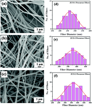 | ||
| Fig. 2 SEM images (a, b and c) and histograms of diameters (d, e and f) of the as-spun Zn(NO3)2/Co(NO3)2/PVP precursor nanofibers for ZCO-1, ZCO-2, and ZCO-3, respectively. | ||
The morphology of the products obtained from precursor nanofibers after thermal treatment in air at 500 °C for 4 h were characterized using SEM (Fig. 3). Fig. 3a displays the morphology of product ZCO-1 and clearly indicates a large quantity of nanoparticles. It is noteworthy that the diameter of these nanoparticles is about 45 nm, and these nanoparticles are further aggregated into larger irregular secondary particles. After sintering at 500 °C for 4 h, one-dimensional tubular morphology of interconnected nanoparticles was observed in Fig. 3b. Interestingly, there are numerous interconnected primary nanoparticles with many nanopores in the walls of these tubular structures, which are clearly visible in the cross-sectional FE-SEM image (inset of Fig. 3b). The as-prepared nano-tubular ZCO-2 product has diameters in the range of 150–250 nm, and the average diameter of primary nanoparticles is about 50 nm. The SEM image of the sintered ZCO-3 product with fibrous structure is shown in Fig. 3c. ZCO-3 showed similar, uniform bead-free nanofibers with diameters mostly in the range of 150–250 nm. After calcination, the morphology and structures of the ZCO final products change with the increase in concentration of nitrates in the precursor polymer solution.
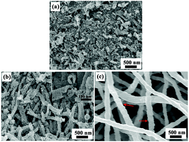 | ||
| Fig. 3 SEM images of the products obtained by sintering precursor nanofibers, (a) ZCO-1, (b) ZCO-2, and (c) ZCO-3. | ||
To further survey the detailed information and structures of the as-prepared ZCO product, TEM and HRTEM analyses were performed. Fig. 4a confirms that the as-prepared ZCO-1 product was composed of nanoparticles. The corresponding HRTEM image of these nanoparticles (Fig. 4b) reveals well-resolved lattice fringes with the measured lattice spacing of 0.286 nm, corresponding to the (220) plane of ZnCo2O4. As shown in Fig. 4c, the as-prepared ZCO-2 nanotubes are composed of interconnected primary nanoparticles with diameters of 40–80 nm and several nanopores in the walls of the ZnCo2O4 nanotube. These holes on the ZCO-2 nanotubes, derived from the high temperature annealing process, may facilitate electrolyte penetration and further provide extra sites for Li+ ion insertion/extraction upon the battery cycling. The HRTEM image in Fig. 4d clearly shows lattice structures with 0.202 nm d-spacing, which is indexed to the (400) plane of the cubic spinel phase of ZnCo2O4 (JCPDS card no. 23-1390). The ZCO-3 product is composed of nanofibers with diameter from 50 nm to 150 nm, as depicted in the TEM image in Fig. 4e. Moreover, individual nanofibers were constituted of interconnected primary nanoparticles with a diameter of approximately 50 nm. This indicates that the nanocrystallites self-assemble to generate a nanoparticle interconnected fibre-like texture in ZCO-3 after sintering. HRTEM image (Fig. 4f) yields a measured d-spacing of 0.286 nm from its lattice fringes, which can be indexed to the interplanar distance of ZnCo2O4 (220) planes, which is in well accordance with the XRD test results.
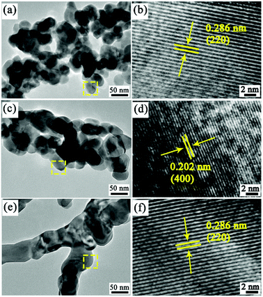 | ||
| Fig. 4 High-resolution TEM images and HRTEM images of the products obtained by sintering precursor nanofibers: (a and b) ZCO-1, (c and d) ZCO-2, and (e and f) ZCO-3. | ||
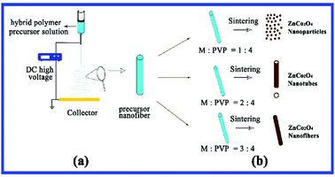
Up to now, it has been reported that the precursor solution critically affects the morphology and structure of resultant nanofibers due to many factors, particularly the amount of the inorganic salts and polymer added. Srinivasan et al.36 reported that the length of nanofibers is regulated by reducing the mass proportion of PVP polymer and metallic salts. It is worth noting that up until the latest investigation, different weight ratios of metallic salts and PVP polymer were controlled for the precursor solution and three typical nanostructured ZnCo2O4 products were obtained after sintering. Fig. 5 shows the general process of electrospinning and diagram of the different nanostructured final products. Mechanism of the formation of nanostructured ZnCo2O4 products has been proposed (Fig. 5b). With a weight ratio of M![[thin space (1/6-em)]](https://www.rsc.org/images/entities/char_2009.gif) :
:![[thin space (1/6-em)]](https://www.rsc.org/images/entities/char_2009.gif) PVP = 1
PVP = 1![[thin space (1/6-em)]](https://www.rsc.org/images/entities/char_2009.gif) :
:![[thin space (1/6-em)]](https://www.rsc.org/images/entities/char_2009.gif) 4, the precursor fibers carry fewer metallic salts, and the as-spun fibers are crushed and turned into nanoparticles (ZCO-1). If the solution weight ratio (M
4, the precursor fibers carry fewer metallic salts, and the as-spun fibers are crushed and turned into nanoparticles (ZCO-1). If the solution weight ratio (M![[thin space (1/6-em)]](https://www.rsc.org/images/entities/char_2009.gif) :
:![[thin space (1/6-em)]](https://www.rsc.org/images/entities/char_2009.gif) PVP = 2
PVP = 2![[thin space (1/6-em)]](https://www.rsc.org/images/entities/char_2009.gif) :
:![[thin space (1/6-em)]](https://www.rsc.org/images/entities/char_2009.gif) 4) is increased, more amounts of metallic salts transfer into the PVP solution, so the as-spun precursor fibers generate nanotubes (ZCO-2) during the sintering process for removing PVP. At the highest metallic salt and PVP polymer weight ratio in this experiment (M
4) is increased, more amounts of metallic salts transfer into the PVP solution, so the as-spun precursor fibers generate nanotubes (ZCO-2) during the sintering process for removing PVP. At the highest metallic salt and PVP polymer weight ratio in this experiment (M![[thin space (1/6-em)]](https://www.rsc.org/images/entities/char_2009.gif) :
:![[thin space (1/6-em)]](https://www.rsc.org/images/entities/char_2009.gif) PVP = 3
PVP = 3![[thin space (1/6-em)]](https://www.rsc.org/images/entities/char_2009.gif) :
:![[thin space (1/6-em)]](https://www.rsc.org/images/entities/char_2009.gif) 4), the precursor solution carries the most metallic salts, and the ZnCo2O4 nanofibers (ZCO-3) could be formed by sintering the as-spun precursor fibers. Overall, the structure and morphology of the ZCO final products can be tuned by varying the weight ratio of nitrates and PVP polymer in the precursor polymer solution. After calcination at high temperature, the lower nitrate weight ratio precursor polymer solution tends to form nanoparticles, and higher concentration of nitrates leads to the formation of fibrous structures (nanotubes and nanofibers).
4), the precursor solution carries the most metallic salts, and the ZnCo2O4 nanofibers (ZCO-3) could be formed by sintering the as-spun precursor fibers. Overall, the structure and morphology of the ZCO final products can be tuned by varying the weight ratio of nitrates and PVP polymer in the precursor polymer solution. After calcination at high temperature, the lower nitrate weight ratio precursor polymer solution tends to form nanoparticles, and higher concentration of nitrates leads to the formation of fibrous structures (nanotubes and nanofibers).
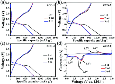
To assess the lithium storage performance of the ZCO-1, ZCO-2, and ZCO-3 nanostructured anode materials, a systematic study on electrochemical performances was implemented at room temperature. Electrochemical behaviors of ZCO-1, ZCO-2, and ZCO-3 as anode materials for LIBs were estimated by galvanostatic discharging and charging, cyclic voltammetry (CV), and EIS survey at 25 °C. The galvanostatic discharge/charge measurements were performed at a constant current density of 200 mA g−1 at potentials from 0.01 to 3 V. Fig. 6a–c describe the first three discharge/charge curves of ZCO-1, ZCO-2, and ZCO-3 samples. In the initial discharge curves of all three samples, two well-defined potential plateaus are observed at 1.04 V, followed by a gradient to the cut-off potential of 0.01 V, which is attributed to the reduction of ZnCo2O4 to metallic Zn and Co as well as the formation of Li2O and solid electrolyte interface (SEI) layers. The voltage profiles of the first charge curves for all three samples from 0.01 to 3.0 V do not plateau as expected, but only three varying degrees of upward slopes are observed. The voltage–capacity curves of the three ZCO samples for the second discharge reaction are inconsistent with that of the first discharge reaction, indicating dissimilar electrochemical reaction mechanisms. The plateau regions are observed at slightly higher potential of about 1.26 V and followed by a sloping profile. The second charge cycle is similar to the first-charge cycle and suggests similar electrochemical reaction process.11,12,37 The first discharge and charge capacities were 1255 and 899 mA h g−1, 1353 and 981 mA h g−1, and 1269 and 922 mA h g−1, for ZCO-1, ZCO-2, and ZCO-3 samples, respectively. Coulombic efficiencies of the three samples for the first cycle were calculated as 71.6%, 77.3%, and 72.6%, respectively. The undeniable reason for decreased capacity after the first circulation is the irreversible electrochemical reaction on cycling, such as the formation of solid electrolyte interface (SEI) layers, stable lithiation production, and oxidation of metal Li to Li2O.38,39
CV is the primary test for studying electrochemical reactions during battery cycling. Based on the similar discharge/charge performance among all the as-prepared three ZCO samples, the ZCO-2 sample was selected to further study its electrochemical performance by the CV test. Fig. 6d shows representative CV curves of the first 3 cycles for the ZCO-2 anode material, which were investigated at a scanning rate of 0.2 mV s−1 between 0.01–3.0 V (vs. Li+/Li). A distinct intense reduction peak is located at 0.8 V, which relates to the reorganization and transformation of ZnCo2O4 nanocrystals to nanoparticles of metallic Co, Zn and LixZn (x ≤ 1) alloy. An irreversible reduction peak at about 0.4 V is observed that disappears in the following cycles, which may attributed to the irreversible formation of metallic oxide Li2O and passivated SEI film. The two peaks located at 1.7 and 2.2 V in the following anodic sweep evolve due to the oxidation of metallic Zn and Co to ZnO and Co3O4, respectively. These results are consistent with those reported in the previous articles.39,40 In the following cycles, the main cathodic peak at 0.8 V positively shifted to 1.0 V, which can be attributed to the polarization of anode material in the first cycle. However, in the second oxidation scan, the positions of the oxidation peaks nearly unchanged. In addition, these CV curves are observed to overlap with each other from the second cycle.
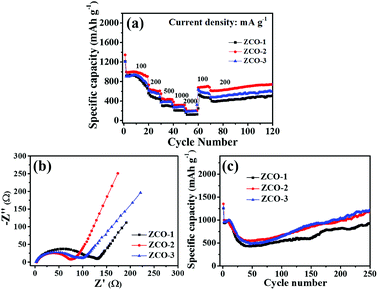
The rate capabilities, EIS impedance analysis tests and long-term cycling tests of all three ZCO anode materials are depicted in Fig. 7. The rate performances of ZCO-1, ZCO-2, and ZCO-3 anodes were investigated by several step galvanostatic measurements at different current densities, as shown in Fig. 7a. The cells were cycled at different current densities ranging from 100 to 2000 mA g−1 to test the rate capability. In order to avoid the induced effect of the electrodes, these cells were tested at 100 mA g−1 for 20 cycles at the beginning. For each of the following steps, 10 continuous charge/discharge cycles were at a stationary condition were measured. All the three anodes exhibit gradually decreasing specific capacity as the current density increases. Impressively, when the testing current density returned back to 100 mA g−1, the capacities for all three anodes bounced to nearly the high values observed in the previously at the same current density. On continuing to test at a current density of 200 mA g−1 for 50 cycles, the three electrode materials still exhibit good cycling stability. The rate capability curves clearly suggest that the ZCO-2 anode exhibits the best rate capability compared with that of the other anodes, while ZCO-3 shows better rate performance than ZCO-1. The high performance of mixed transition metal anode materials is mostly due to the kinetics of electrochemical redox reaction processes, involving the diffusion of lithium ions and electrons to/from the particle/electrolyte interfaces. Moreover, electrochemical performances of the batteries were mostly influenced by the dimensions, morphologies, and structures of the electrode materials.15,17 Through the strategy proposed in this study, fibrous structured ZnCo2O4 anodes can exhibit increased energy densities and improved rate performances. The pores in ZCO-2 (ZnCo2O4 nanotubes) and ZCO-3 (ZnCo2O4 nanofibers) could assist fast diffusion of the electrolyte, which is very crucial for high power storage applications. In addition, the one-dimensional fibrous structure can effectively alleviate volume expansion/shrinkage of ZnCo2O4 during the charge and discharge cycles.
To gain a further understanding of the differing rate performances of the ZCO-1, ZCO-2, and ZCO-3 anodes, EIS curves for the three anodes are presented in Fig. 7b. The Nyquist plots of the three anodes (Fig. 7b) show a similar pattern, with a curved line at high-middle frequencies and an inclined straight line at low frequencies, reflecting the electrochemical reaction activity at the electrode interface and the electron/ion conductivity, and Warburg impedance (W), respectively.41,42 Clearly, the semicircle diameter in the EIS plot for ZCO-2 electrode is the smallest of the three electrodes. Thus, the ZCO-2 anode possesses the lowest energy barrier for lithium ion diffusion and has the fastest faradaic reaction, which facilitates better high-rate performance of the ZCO-2 anode in comparison with the other anodes. Moreover, the ZCO-2 anode also possesses the highest Li+ diffusion coefficient among the three samples.43,44
Fig. 7c compares the cycling performances of the three anodes at 200 mA g−1 in the voltage range of 0.01–3 V. A rapid capacity fading in the initial 30 cycles is observed. This commonly occurring phenomenon can be ascribed to the gradually arisen complicated reaction processes and the self-reconstruction of ZnCo2O4 anode materials.45 Subsequently, a slow increase in capacity taking place between 30 and 275 cycles may be attributed to the partial activation of polymeric gel-like film decomposed onto the electrode, which enabled the slow capacity recovery.46–48 The discharge capacities of ZCO-1, ZCO-2, and ZCO-3 anodes after 275 cycles are 1007, 1180, and 1105 mA h g−1, showing 80.2%, 87.2%, and 87.0% retention of the discharge capacity, respectively. The better performance for ZCO-2 and ZCO-3 electrodes can be ascribed to their volume change accommodation and fast electron/ion transportation along the 1D fibrous structured ZnCo2O4.49,50
Distinctly, the discharge capacities of these ZCO anodes tend to vary as the weight ratio of metallic salts and PVP polymer increases, indicating that the structure of the anode materials can affect the electrochemical performance. As a result, with an appropriate structure, the active materials can be used in electrochemical cycling of batteries with high efficiency.
Conclusions
In summary, ZnCo2O4 materials with tunable structures have been successfully fabricated using a two-step process, combining the environment-friendly and easy-to-operate electrospinning and a simple heat-treatment technique. By simply controlling the weight ratios of metallic salts and PVP polymer, ZnCo2O4 nanoparticles, nanotubes, and nanofibers could be selectively prepared. As anodes for LIBs, these materials exhibit good reversible charge/discharge capacity, rate performance, and long cycling lifespan. Particularly, the discharge capacity for ZCO-2 is about 1180 mA h g−1 at a current density of 200 mA g−1 after 275 cycles, which is much higher than that for ZCO-1 nanoparticles at the same current density. These tunable structured ZnCo2O4 anode materials can be promising candidates for high-performance LIBs and also pave the way for controlling the final morphology and structure of products of electrospinning.Conflicts of interest
There are no conflicts to declare.Acknowledgements
We gratefully acknowledge the support of this research by the Natural Science Foundation of Jilin Province (No. 20170101128JC), National Natural Science Foundation of China (No. 201601018), the Science and Technology Research Project of the Education Department of Jilin Province during the 13th five-year-plan period (No. 2016-359, 2016-382), and Industrial Technology Research and Development Project of Jilin Province Development and Reform Commission (No. 2017C052-4).References
- H. Li, Z. X. Wang, L. Q. Chen and X. J. Huang, Adv. Mater., 2009, 21, 4593–4607 CrossRef CAS.
- J. B. Goodenough and K. S. Park, J. Am. Chem. Soc., 2013, 135, 1167–1176 CrossRef CAS PubMed.
- D. Aurbach, J. Electrochem. Soc., 2015, 162, A2379 CrossRef CAS.
- E. J. Berg, C. Villevieille, D. Streich, S. Trabesinger and P. Novák, J. Electrochem. Soc., 2015, 162, A2468–A2475 CrossRef CAS.
- K. Xu, Chem. Rev., 2014, 114, 11503–11618 CrossRef CAS PubMed.
- P. G. Bruce, B. Scrosati and J. M. Tarascon, Angew. Chem., Int. Ed., 2008, 47, 2930–2946 CrossRef CAS PubMed.
- J. W. Choi and D. Aurbach, Nat. Rev. Mater., 2016, 1, 16013 CrossRef CAS.
- F. Luo, B. Liu, J. Zheng, G. Chu, K. Zhong, H. Li, X. Huang and L. Chen, J. Electrochem. Soc., 2015, 162, A2509–A2528 CrossRef CAS.
- M. V. Reddy, G. V. Subba Rao and B. V. Chowdari, Chem. Rev., 2013, 113, 5364–5457 CrossRef CAS PubMed.
- F. Wu, J. Bai, J. Feng and S. Xiong, Nanoscale, 2015, 7, 17211–17230 RSC.
- Y. Qiu, S. Yang, H. Deng, L. Jin and W. Li, J. Mater. Chem., 2010, 20, 4439 RSC.
- L. L. Hu, B. H. Qu, C. C. Li, Y. J. Chen, L. Mei, D. N. Lei, L. B. Chen, Q. H. Li and T. H. Wang, J. Mater. Chem. A, 2013, 1, 5596–5602 RSC.
- J. Bai, K. Wang, J. Feng and S. Xiong, ACS Appl. Mater. Interfaces, 2015, 7, 22848–22857 CrossRef CAS PubMed.
- H. Niu, X. Yang, H. Jiang, D. Zhou, X. Li, T. Zhang, J. Y. Liu, Q. Wang and F. Y. Qu, J. Mater. Chem. A, 2015, 3, 24082–24094 RSC.
- H. B. Wu, J. S. Chen, H. H. Hng and X. W. Lou, Nanoscale, 2012, 4, 2526–2542 RSC.
- J. Liang, X. Gao, J. Guo, C. Chen, K. Fan and J. Ma, Sci. China Mater., 2017, 61, 30–38 CrossRef.
- G. Chen, L. Yan, H. Luo and S. Guo, Adv. Mater., 2016, 28, 7580–7602 CrossRef CAS PubMed.
- J. Bai, X. Li, G. Liu, Y. Qian and S. Xiong, Adv. Funct. Mater., 2014, 24, 3012–3020 CrossRef CAS.
- M. S. Islam and C. A. Fisher, Chem. Soc. Rev., 2014, 43, 185–204 RSC.
- X. Wang, J. Feng, Y. Bai, Q. Zhang and Y. Yin, Chem. Rev., 2016, 116, 10983–11060 CrossRef CAS PubMed.
- H. Liu, X. Wang, H. Xu, W. Yu, X. Dong, Y. Yang, H. Zhang and J. Wang, Dalton Trans., 2017, 46, 11031–11036 RSC.
- W. Zeng, L. Wang, H. Shi, G. Zhang, K. Zhang, H. Zhang, F. Gong, T. Wang and H. Duan, J. Mater. Chem. A, 2016, 4, 8233–8241 RSC.
- J. Pu, Z. Liu, Z. Ma, J. Wang, L. Zhang, S. Chang, W. Wu, Z. Shen and H. Zhang, J. Mater. Chem. A, 2016, 4, 17394–17402 RSC.
- W. Kang, Y. Tang, W. Li, X. Yang, H. Xue, Q. Yang and C. S. Lee, Nanoscale, 2015, 7, 225–231 RSC.
- S. Thenmozhi, N. Dharmaraj, K. Kadirvelu and H. Y. Kim, Mater. Sci. Eng., B, 2017, 217, 36–48 CrossRef CAS.
- C. L. Zhang and S. H. Yu, Chem. Soc. Rev., 2014, 43, 4423–4448 RSC.
- C. Niu, J. Meng, X. Wang, C. Han, M. Yan, K. Zhao, X. Xu, W. Ren, Y. Zhao, L. Xu, Q. Zhang, D. Zhao and L. Mai, Nat. Commun., 2015, 6, 7402 CrossRef PubMed.
- J. W. Jung, C. L. Lee, S. Yu and I.-D. Kim, J. Mater. Chem. A, 2016, 4, 703–750 RSC.
- E. C. Self, R. Wycisk and P. N. Pintauro, J. Power Sources, 2015, 282, 187–193 CrossRef CAS.
- B. Varghese, T. C. Hoong, Z. Yanwu, M. V. Reddy, B. V. R. Chowdari, A. T. S. Wee, T. B. C. Vincent, C. T. Lim and C. H. Sow, Adv. Funct. Mater., 2007, 17, 1932–1939 CrossRef CAS.
- Z. S. Wu, W. Ren, L. Wen, L. Gao, J. Zhao, Z. Chen, G. Zhou, F. Li and H. M. Cheng, ACS Nano, 2010, 4, 3187 CrossRef CAS PubMed.
- S. Vijayanand, P. A. Joy, H. S. Potdar, D. Patil and P. Patil, Sens. Actuators, B, 2011, 152, 121–129 CrossRef CAS.
- W. Luo, X. Hu, Y. Sun and Y. Huang, J. Mater. Chem., 2012, 22, 8916 RSC.
- T. F. Hung, S. G. Mohamed, C. C. Shen, Y. Q. Tsai, W. S. Chang and R. S. Liu, Nanoscale, 2013, 5, 12115–12119 RSC.
- B. Sahoo and P. K. Panda, Ceram. Int., 2012, 38, 5189–5193 CrossRef CAS.
- P. F. Teh, Y. Sharma, S. S. Pramana and M. Srinivasan, J. Mater. Chem., 2011, 21, 14999–15008 RSC.
- Y. Sharma, N. Sharma, G. V. Subba Rao and B. V. R. Chowdari, Adv. Funct. Mater., 2007, 17, 2855–2861 CrossRef CAS.
- X. Xu, K. Cao, Y. Wang and L. Jiao, J. Mater. Chem. A, 2016, 4, 6042–6047 RSC.
- H. Long, T. Shi, S. Jiang, S. Xi, R. Chen, S. Liu, G. Liao and Z. Tang, J. Mater. Chem. A, 2014, 2, 3741–3748 RSC.
- M. V. Reddy, K. Y. H. Kenrick, T. Y. Wei, G. Y. Chong, G. H. Leong and B. V. R. Chowdari, J. Electrochem. Soc., 2011, 158, A1423–A1430 CrossRef CAS.
- J. Y. Liao, D. Higgins, G. Lui, V. Chabot, X. Xiao and Z. Chen, Nano Lett., 2013, 13, 5467–5473 CrossRef CAS PubMed.
- S. Shilpa, B. M. Basavaraja, S. B. Majumder and A. Sharma, J. Mater. Chem. A, 2015, 3, 5344–5351 RSC.
- M. Zhen, X. Guo, G. Gao, Z. Zhou and L. Liu, Chem. Commun., 2014, 50, 11915–11918 RSC.
- M. M. Zhen, L. Liu and C. Wang, Microporous Mesoporous Mater., 2017, 246, 130–136 CrossRef CAS.
- G. Zhang, L. Yu, H. B. Wu, H. E. Hoster and X. W. Lou, Adv. Mater., 2012, 24, 4609–4613 CrossRef CAS PubMed.
- S. Laruelle, S. Grugeon, P. Poizot, M. Dollé, L. Dupont and J. M. Tarascon, J. Electrochem. Soc., 2002, 149, A627 CrossRef CAS.
- Y. Y. Hu, Z. Liu, K. W. Nam, O. J. Borkiewicz, J. Cheng, X. Hua, M. T. Dunstan, X. Yu, K. M. Wiaderek, L. S. Du, K. W. Chapman, P. J. Chupas, X. Q. Yang and C. P. Grey, Nat. Mater., 2013, 12, 1130–1136 CrossRef CAS PubMed.
- Y. Wang, Z. G. Huang and Y. J. Wang, J. Mater. Chem. A, 2015, 3, 21314–21320 RSC.
- L. Mai, X. Tian, X. Xu, L. Chang and L. Xu, Chem. Rev., 2014, 114, 11828–11862 CrossRef CAS PubMed.
- X. Li, J. Xu, L. Mei, Z. Zhang, C. Cui, H. Liu, J. Ma and S. Dou, J. Mater. Chem. A, 2015, 3, 3257–3260 RSC.
Footnote |
| † Electronic supplementary information (ESI) available. See DOI: 10.1039/c8ra08066f |
| This journal is © The Royal Society of Chemistry 2018 |

