 Open Access Article
Structural design of polyurethane/poly(butylene succinate)/polycaprolactone compounds via a multilayer-assembled strategy: achieving tunable triple-shape memory performances†
Yu Zheng ,
Xiaoying Ji,
Qingwen Wang,
Jiabin Shen
 * and
Shaoyun Guo*
Polymer Research Institute of Sichuan University, State Key Laboratory of Polymer Materials Engineering, Chengdu, Sichuan 610065, P. R. China. E-mail: shenjb@scu.edu.cn; nic7702@scu.edu.cn
First published on 19th December 2018
Abstract
Shape memory polymeric materials composed of thermoplastic polyurethane (TPU), poly(butylene succinate) (PBS), and polycaprolactone (PCL) were prepared through layer-multiplying co-extrusion of blends. With the two well-separated melting transitions respectively from PCL and PBS, the multicomponent compounds realized triple-shape memory effect. By tailoring the structure of the individual layer, the multilayer systems with designable phase morphology were fabricated, which developed tunable shape memory performances. Particularly, the multi-continuous structure containing alternating layers of TPU and the co-continuous PBS/PCL blend presented the optimal shape fixity and recovery ratios, whose minimum value can reach 84%. It was revealed that the high phase continuity along the deformation direction and the strong interfacial shearing effect promoted the ability to fix the temporary shapes and recover them to the permanent state. In addition, the multi-continuous structure maximized the synergy of the components in mechanical properties, resulting in an excellent balance of tensile strength and ductility. The present strategy for morphology control of multicomponent structures provides a promising method to fabricate outstanding triple-shape memory polymers with optimal mechanical properties.
1. Introduction
Shape memory polymers (SMPs), as a kind of smart materials, can provide the ability to fix a deformed shape and recover to the original shape in response to an external stimulus.1–6 In recent years, the field of SMPs has witnessed a fast growth because of the intrinsic versatility of SMPs in versatile applications ranging from sensors to aerospace structures and medical devices.7–11 For further extending the capacity of SMPs, numerous SMPs with novel properties have been developed and the triple-shape memory polymer (TSMP) is the typical one. Unlike the classic dual-SMPs that memorize only one temporary shape in a thermo-mechanical cycle,12 TSMPs can fix two temporary shapes and recover to the original shape by continuous heating,13–16 which meet the requirement of more complex deformation.Generally, efficient methods to fabricate TSMPs include multicomponent polymers with well-separated thermal transitions and polymers with a broad phase transition. By selectively dividing the sufficiently broad thermal transition into sequence domains, some polymers can exhibit triple-shape memory effect (TSME). For instance, Xie found that the pure perfluorosulphonic acid (PSFA) ionomer possessing a broad glass transition can present TSME and even multiple-shape memory effect.17 In another work, Samuel et al. prepared a TSMP by simply blending the miscible poly(methyl methacrylate) (PMMA) and poly(L-lactide acid) (PLLA) to broaden the glass transition temperature range, and tunable TSME was achieved for the blend with 50 wt% PLLA via tuning the intermediate shapes.18 However, the chain relaxation of this type of TSMP occurs at any temperature within the broad thermal transition, which usually leads to unstable temporary shapes. Besides, the choice of the thermomechanical conditions would dramatically influence the final TSME,19 so that more care should be taken to optimize the performance.
In contrast, the multicomponent polymers realize TSME based on the distinct elastic modulus status resulted from the well-separated thermal transitions, which can make it more efficient to set the thermomechanical conditions and fix the temporary shapes.20 As an example, Behl et al. synthesised a TSMP network using PCL and poly(cyclohexyl methacrylate) (PCHMA).21 The switching temperature (Ts) at different shape memory stages can be easily selected according to the melting transition of PCL and the glass transition of PCHMA. Moreover, both of the shape fixity ratio (Rf) and shape recovery ratio (Rr) approximated 100% when the PCL content was between 35 and 60 wt%. After that, the same group developed TSME by fabricating another copolymer network composed of poly(ω-pentadecalactone) (PPD) and PCL with separated Tm's.22 Although many works have been accomplished,23–26 the fabrication methods still need improvement and development.
Polymer blending, which can integrate the advantages of two or more materials, has been the rising star in fabrication of SMPs because of its easy processability.27,28 Some reports have stated that the dual-shape memory effect can be easily achieved by blending one permanent component (PC) which is in charge of memorizing the permanent shape and another switching component (SC) with reversible phase transition.29–32 Inspired by that, incorporating additional SC's through melt processing seems like an effective route to develop TSMPs. By so far, some multi-phase blends possessing TSME have been reported, such as polyethylene (PE)/polycyclooctene blends and thermoplastic polyurethane (TPU)/olefin block copolymer/PCL blends.33,34 For the shape memory compounds, the co-continuous morphology was known to show better shape memory performance.20,35 However, it is hard to tailor a multicomponent structure to be co-continuous via conventional melt processing because of the numerous influencing factors (e.g. viscosity ratios, interfacial tensions, processing parameters, and so on).36–38
The layer-multiplying co-extrusion, as an advanced processing technology, has attracted tremendous attention due to its application in developing functional materials with versatile unique properties.39–45 As schematically illustrated in Fig. 1, the multilayer structure possessing a special co-continuous morphology can be prepared through combining an assembly of layer-multiplying elements (LMEs) with two extruders, regardless of the influencing factors proposed in the blending system. Moreover, the structure of the individual layer which may be a blend can be tailored before the layer-assembly process, thus being beneficial for incorporating more SC's, meanwhile, achieving morphology control. Besides, the Baer's group (Case Western Reserve University) has reported that the high phase continuity and numerous interfaces of multilayer SMPs would greatly facilitate stress transferring and load distribution, which maximizes synergies among the shape memory domains.46,47 Accordingly, the layer-multiplying co-extrusion that enables the structural design of the multicomponent system to become controllable and efficient is believed to be a promising strategy for preparing excellent TSMPs.
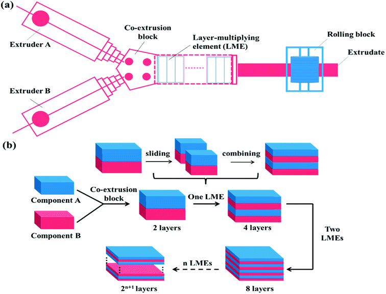 | ||
| Fig. 1 Schematic of the (a) layer-multiplying co-extrusion system and (b) production progress of multilayer structure. | ||
In this work, multicomponent structures with tunable phase continuity were fabricated through layer-multiplying co-extrusion. The poly(butylene succinate) (PBS)/PCL blend with co-continuous structure was coextruded with neat TPU, for formation of a special multi-continuous morphology. Additionally, another multilayer structure with continuous PCL and dispersed PBS was prepared by coextruding the co-continuous TPU/PCL blend and the sea-island TPU/PBS blend. TSME of the multilayer systems was investigated and the operative shape memory mechanism related to the phase continuity was discussed. The influence of the morphological distinctions on mechanical properties was also explored. Furthermore, the materials used in this work have excellent biocompatibility,32,48,49 so that the multilayer TSMP is of great potential in biomedical applications.
2. Experimental
2.1. Materials
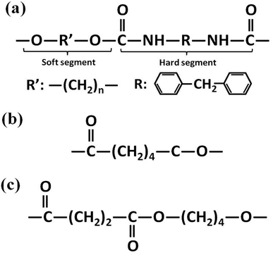
Polyester-based TPU (Elastogran® S85A11), with a Shore A hardness of about 85, a density of 1.23 g cm−3, and 4,4′-methane diisocyanate (MDI) acting as the hard segments, was purchased from BASF group (Germany). Commercial PCL (CAPA6800) with a density of 1.11 g cm−3 was purchased from Perstorp Corp. (UK). PBS (1001MD) with a density of 1.26 g cm−3 was purchased from Showa Denko Corp. (Japan). The molecular structures of the materials are illustrated in Fig. 2.2.2. Specimen preparation
TPU and PBS were dried at 80 °C for 40 h and PCL was dried at 40 °C for 24 h in a vacuum oven before melt processing. After that, the PBS/PCL, TPU/PBS, and TPU/PCL blend pellets (denoted as SLB, TSB, and TLB) respectively contained 50 vol% PCL, 50 vol% PBS and 50 vol% PCL were prepared using a SHJ-20 twin-screw extruder (screw diameter is 21.7 mm, L/D = 40![[thin space (1/6-em)]](https://www.rsc.org/images/entities/char_2009.gif) :
:![[thin space (1/6-em)]](https://www.rsc.org/images/entities/char_2009.gif) 1, Nanjing Giant Co. Ltd., China) with an extrusion temperature of 185 °C and extrusion rate of 150 rpm. Then, the multilayer SMPs consisting of alternating TPU and SLB layers were prepared through the layer-multiplying co-extrusion technology. As shown in Fig. 1a, TPU and SLB were simultaneously extruded from different extruders, combined as a two-layer melt in the co-extrusion block, and then flowed through an assembly of LMEs. In a LME, the melt was sliced into two left and right sections by a divider and then recombined vertically, leading to double the number of layers, Fig. 1b. When n LMEs were applied, the materials with 2(n+1) layers can be produced eventually, while the overall thickness of the multilayers remain unchanged. In this work, 64-layer material was fabricated by applying 5 LMEs. By controlling the co-extrusion speed, the total thickness of the extrudate was maintained at about 1.0 mm, and the thickness ratio of the TPU and SLB layers was kept at 1
1, Nanjing Giant Co. Ltd., China) with an extrusion temperature of 185 °C and extrusion rate of 150 rpm. Then, the multilayer SMPs consisting of alternating TPU and SLB layers were prepared through the layer-multiplying co-extrusion technology. As shown in Fig. 1a, TPU and SLB were simultaneously extruded from different extruders, combined as a two-layer melt in the co-extrusion block, and then flowed through an assembly of LMEs. In a LME, the melt was sliced into two left and right sections by a divider and then recombined vertically, leading to double the number of layers, Fig. 1b. When n LMEs were applied, the materials with 2(n+1) layers can be produced eventually, while the overall thickness of the multilayers remain unchanged. In this work, 64-layer material was fabricated by applying 5 LMEs. By controlling the co-extrusion speed, the total thickness of the extrudate was maintained at about 1.0 mm, and the thickness ratio of the TPU and SLB layers was kept at 1![[thin space (1/6-em)]](https://www.rsc.org/images/entities/char_2009.gif) :
:![[thin space (1/6-em)]](https://www.rsc.org/images/entities/char_2009.gif) 1. The processing conditions were the same as those for the preparation of SLB pellets. Similarly, the 64-layer TSB/TLB specimen with the whole thickness of 1.0 mm was produced under the same conditions. What should be noted is that the thickness ratio of TSB and TLB is also 1
1. The processing conditions were the same as those for the preparation of SLB pellets. Similarly, the 64-layer TSB/TLB specimen with the whole thickness of 1.0 mm was produced under the same conditions. What should be noted is that the thickness ratio of TSB and TLB is also 1![[thin space (1/6-em)]](https://www.rsc.org/images/entities/char_2009.gif) :
:![[thin space (1/6-em)]](https://www.rsc.org/images/entities/char_2009.gif) 1, in order to maintain the composition unchanged. For comparison, TPU/PBS/PCL blend (donated as TSLB) with the same composition as that in the multilayer systems was produced by extruding from one of extruders of above co-extrusion system, for keeping a similar processing history.
1, in order to maintain the composition unchanged. For comparison, TPU/PBS/PCL blend (donated as TSLB) with the same composition as that in the multilayer systems was produced by extruding from one of extruders of above co-extrusion system, for keeping a similar processing history.
2.3. Differential scanning calorimetry (DSC)
For determining the Ts at the different shape memory stages, the heating and cooling curves of the samples were recorded on a DSC (Q20, TA Instrument, USA) under nitrogen. Each 5–7 mg sample was heated from 20 to 160 °C at a heating rate of 10 °C min−1 and maintained at 160 °C for 5 min, then the sample was cooled down to 0 °C at a cooling rate of 10 °C min−1.The degree of crystallizations (Xc) of PCL and PBS in each sample was calculated as follows:
2.4. Morphological observation
The microstructure of each specimen was observed using an Olympus BX51 polarizing light microscope (PLM) equipped with a camera. A thin slice about 10 μm in thickness was obtained by a microtome from each sample perpendicular to the extruding direction.The morphological structure of the individual layer was further observed by using a scanning electron microscope (SEM, JEOL JSM-5900LV) under a proper accelerating voltage. The specimens were first cryofractured in liquid nitrogen, then SLB and TLB were immersed in acetone to selectively etch the dispersed PCL, TSB and TSLB were immersed in dichloromethane to selectively etch the dispersed PBS or/and PCL. Prior to visualization, the surface of each specimen was coated with a layer of gold in a vacuum chamber.
2.5. Shape memory test
The samples for shape memory testing were cut from the extruded films into rectangular specimens with dimensions of 10 mm (length) × 2 mm (width) × 1.0 mm (thickness). TSME experiments were carried out on the dynamic mechanical analyzer (Q800, TA Instrument) in controlled force mode. A typical thermomechanical cycle involves the following steps: (1) stretching the sample at Ts1 to a certain strain (εm1) with a constant stress, (2) cooling to a lower Ts2 and then removing the load for 5 min to obtain the first temporary strain (εf1), (3) a second force-controlled stretching was performed at Ts2 to reach the maximum strain (εm2), (4) cooling to 25 °C and again removing the stress to gain the second temporary strain (εf2), and (5) a free-strain recovery was first performed at Ts2 for 20 min to the recovered strain (εr2), subsequently performed at Ts1 for 20 min to the final strain (εr1). Rr and Rf were respectively calculated by using following eqn (1) and (2):17,18
 | (1) |
 | (2) |
2.6. Dynamic mechanical analysis
The storage moduli at different temperatures were measured through the DMA Q800 from TA Instruments. Each sample with dimensions of 10 mm (length) × 4 mm (width) × 1.0 mm (thickness) was heated at heating rate of 3 °C min−1 from 0 to 160 °C using a stretching mode. The testing frequency was 10 Hz.2.7. Creep-recovery test
The creep-recovery curves were measured using the DMA Q800 from TA Instruments at the Ts. Each sample was first stretched to a certain strain under the constant stress and then the load was released instantaneously. The creeping process lasted for 20 min and the recovered strain as a function of the creeping time was recorded.2.8. Tensile tests
Tensile tests were performed using an Instron 4302 tension machine (Canton, MA, USA) at a crosshead speed of 100 mm min−1 in accordance with ASTM D638. At least five specimens for each sample were tested, and the average value was calculated.3. Results and discussion
3.1. Macrostructure
Fig. 3 exhibits the PLM pictures of the blending and multilayer specimens. The parallel-assembled bright and dark layers of TPU/SLB are respectively corresponding to the semicrystalline SLB and amorphous TPU. Besides, the individual SLB demonstrates the typical co-continuous morphology, which can be proved by the SEM picture showed in Fig. S1.† Thus, a special multi-continuous structure with numerous interfaces can be fabricated by coextruding SLB and TPU. TSB/TLB also shows a multilayer structure composed of alternating semicrystalline layers. However, the interfaces in TSB/TLB are more ambiguous than those in TPU/SLB because of the molecular diffusion of the TPU matrix during the layer-multiplying process. Additionally, as seen in Fig. S2,† TLB appears to be co-continuous, while TSB exhibits the sea-island morphology. Accordingly, TSB/TLB can be regarded as a TPU-based blend in which the continuous PCL and island-like PBS are alternately dispersed. For the conventional blend, it can be seen that the bright crystals of PBS and PCL are dispersed in the amorphous TPU matrix. By etching both of PBS and PCL with dichloromethane,52 the typical sea-island structure can be observed through the SEM test, Fig. S3.† Consequently, the multilayer assembly of different structures can produce multicomponent systems with tunable phase continuity, which is believed to result in distinct shape memory performance.3.2. Thermal behaviors
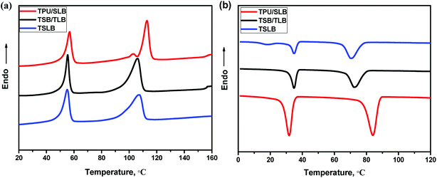
As mentioned earlier, the TSME can be achieved by incorporating two reversible domains with well-separated thermal transitions. Fig. 4 displays the DSC heating and cooling curves of the blending and multilayer specimens. From Fig. 4a, it can be seen that all the curves show a similar melting transition process of PCL and have the same Tm at around 56 °C as that of PCL, irrespective of the structural distinctions. On the other hand, PBS in TPU/SLB exhibits a dual melting behavior with two Tm's at approximately 103 and 113 °C ascribed to its melt-recrystallization effect.53 However, both of TSB/TLB and TSLB have only a single melting peak of PBS at about 107 °C, which is basically consistent with the DSC curve of TSB exhibited in Fig. S4.† Unlike the TPU/SLB multilayer structure with numerous interfaces, TPU is directly blended with PBS in TSB/TLB and TSLB. Thus, the melt-recrystallization effect of PBS may be suppressed by the hydrogen-bonding interaction between TPU and PBS.54 Although PBS demonstrates different melting behavior, all the specimens can provide two well-separated Tm's to meet the prerequisite for realizing TSME.As for a triple-shape memory cycle, the fixation of the first temporary shape (S1) is crucial but always more difficult due to the chain mobility of the SC owning the lower phase transition temperature. In this study, when S1 was fixed at Ts2 which should be higher than the Tm of PCL to allow a second deformation, the molten PCL would cause partial recovery. Fortunately, as seen in Fig. 4b, although the crystallization temperature (Tc) of PBS would be decreased after blending with TPU, which is still appropriately higher than the Tm of PCL, thus can provide a temperature interval to choose a proper Ts2 where PBS can crystallize to maintain S1. Similarly, after cooling the second temporary shape (S2) to the room temperature, the crystalline PCL would make contribution to the shape fixation. Hence, the well-separated Tc's/Tm's of PCL and PBS endow the specimens with great potential to demonstrate efficient TSME.
3.3. Shape memory performance
Based on above results of thermal behaviors, TSME of each specimen was investigated by designing a triple-shape memory cycle, as shown in Fig. 5. The Ts1 was chosen at 125 °C where both of PBS and PCL are molten to obtain S1, and then the deformation was fixed by cooling to the Ts2 of 70 °C where PBS can crystallize to provide mechanical support and PCL is still molten to allow the second shaping. After fixing the S2 by cooling to 25 °C, a subsequent recovery under continuous heating was conducted to characterize the recoverability. The corresponding Rf and Rr at each stage are calculated and compared in Table 1. The Rf2 and Rr2 of TSLB are only 78.2 and 66.0%, respectively, suggesting that the fixation of S2 and the recovery from S2 to S1 are not effective. After tailoring PCL or/and PBS to be continuous through layer-multiplying co-extrusion, all the values are greatly improved. For the TSB/TLB specimen, only R2 is relatively low, but is still around 75%, and both of Rf1 and Rr1 are beyond 88%. Besides, the minimum Rf or Rr value of TPU/SLB can even reach 84%, although the strains in Fig. 5 show higher values for TPU/SLB specimens, which further indicates that the multi-continuous structure can indeed better promote the shape memory performances.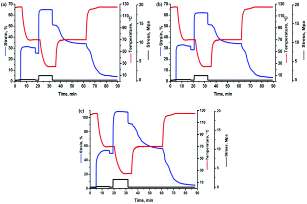 | ||
| Fig. 5 The triple-shape memory cycles with Ts's of 70 and 125 °C of the (a) TSLB, (b) TSB/TLB, and (c) TPU/SLB specimens. | ||
| Sample | Rf1 | Rf2 | Rr2 | Rr1 |
|---|---|---|---|---|
| TSLB | 83.8% | 78.2% | 66.0% | 83.1% |
| TSB/TLB | 89.6% | 82.6% | 75.2% | 88.1% |
| TPU/SLB | 92.9% | 84.5% | 83.9% | 90.3% |
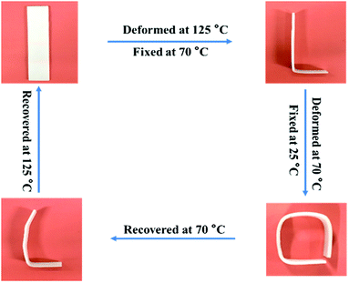
Fig. 6 exhibits the macroscopic triple-shape memory progress of TPU/SLB recorded by a digital camera. The stripe was first deformed to a “L” shape at 125 °C and fixed at 70 °C for 5 min to obtain S1; then it was further deformed to a square shape and cooled to 25 °C to fix S2. After that, the S2 was recovered to S1 by heating the sample to 70 °C and isothermal treatment for 10 min. Subsequently, the sample was further heated to 125 °C and isothermally treated for another 10 min. It can be found that the two temporary shapes are well fixed and the original shape is almost entirely recovered. Accordingly, the TPU/SLB can indeed present a valuable TSME with excellent and balanced shape memory performances over all stages.
3.4. Shape memory mechanism
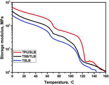
With regard to a multicomponent SMP, the shape memory property is always governed by the phase structure.29–32 For this study, above results of morphological observation have revealed that different geometric organization of the components would produce diverse macrostructures as schematically illustrated in Fig. 7, resulting in distinct TSME. It can be seen that the phase continuity of PBS and PCL are gradually enhanced ranging from TSLB to TPU/SLB. Hence, the shape memory mechanism of TSME, which seems to be related to the phase continuity, is worth discussing.When S1 was fixed at 70 °C, the specimen tended to recover because TPU preserved the stain energy and PCL is molten, but most of the deformation would be maintained with the mechanical support provided by the crystallized PBS. For the TPU/SLB specimen, the continuous PBS can serve as the framework of the SLB layers, so that the recovery tendency of PCL and TPU can be well restrained. In contrast, the dispersed PBS in the TPU matrix would obviously allow more shape recovery, leading to the reduction of Rf1. Moreover, the storage moduli of the specimens at 70 °C are gradually enhanced with the increase of the phase continuity of PBS, Fig. 8, further indicating that the continuous PBS can provide a stronger mechanical support to fix the temporary deformation. Similarly, as S2 was fixed at 25 °C, the multilayer systems with continuous PCL demonstrate the better shape fixity. Besides, it should be noticed that the Rf1 of each specimen is larger than Rf2. Actually, Rf is significantly influenced by the amorphous domains of PBS and PCL which can induce recovery under the driving force provided by TPU due to their extremely low Tg's of about −30 and −60 °C, respectively. However, PBS has a much higher Xc than that of PCL, Table S1,† meaning that there may be more less active domains when S1 was fixed by PBS. Additionally, the specimens have a quite greater storage modulus at 70 °C, which would produce larger strain energy to be stored in the second shaping progress, so that the recovering tendency would become stronger when S2 was fixed. Accordingly, the specimen exhibits a lower Rf at the second shape fixing stage.
In the recovery progress, the performance of each specimen turns to be governed by TPU because the molten PBS and PCL with an extremely low modulus would fail to store the strain energy. For the TPU/SLB specimen, the parallel-assembled SLB and TPU layers should always obtain the same strain during deformation. Thus, the TPU layers can efficiently promote the adjacent SLB layers to recover through the interfacial shearing effect. However, the TSB/TLB multilayer system has a slightly worse Rr, which may be resulted from the lower phase continuity along the stretching direction and the weaker interfacial shearing effect induced by the interfacial diffusion of TPU. With regard to TSLB with a sea-island structure, it can also be divided into many parallel layers in which the components are assembled in series. On the basis of the classic viscoelastic theory,55 the strain of the series-connected components should be dominated by their own viscoelasticity, so that the recovery of TPU has less effect on that of PBS and PCL. Consequently, TSLB would produce more irreversible deformation, which can be further evidenced through the creep-recovery experiment. Fig. 9 shows the evolution of recovered strain during the creeping progress of each specimen at the two Ts's of 70 and 125 °C. After creeping for 20 min at 125 °C, the TPU/SLB and TSB/TLB specimens have the recovered strains of 85.9 and 79.6%, respectively, while the final strain of the blend is 76.1%. When the creep temperature is decreased to 70 °C, the multilayer structures also exhibit the larger recoverability than that of the blend. These results reveal that the multilayer systems with higher phase continuity and a plenty of interfaces can indeed hold a greater promise in optimizing Rr. However, for the individual specimen, a lower Rr is obtained at 70 °C. Taking the TSLB specimen for instance, the Rr is dramatically decreased from 78.2 to 66.0%, when the Ts is reduced from 125 to 70 °C. Unlike that both of PBS and PCL would melt at the Ts1 of 125 °C, PBS is semi-crystalline at the Ts2 of 70 °C. As a result, the second shaping progress would create some destruction and orientation of the PBS crystals which would fail to be recovered until melting again, thus deteriorating Rr after reheating to 70 °C at the first recovering stage. By further heating to Ts1, PBS would be molten to allow a full recovery, and a larger Rr is reasonably obtained.
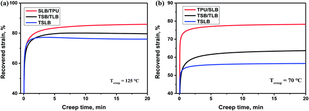 | ||
| Fig. 9 Evolution of recovered strain of the specimens during the creeping progresses at (a) 125 °C and (b) 70 °C. | ||
3.5. Mechanical properties
Apart from promising competitive shape memory performance, favorable mechanical properties are also important for TSMPs to realize practical application. Thus, tensile tests were conducted to explore the influence of morphological distinctions among the specimens on the tensile strength (σs) and elongation at break (εb). The stress–strain curves and resulting data are showed in Fig. 10. With the dispersed PBS and PCL, TSLB shows the typical elastomeric tensile property with σs of 31.9 MPa and excellent εb of 1274.7%. By transforming PCL into the continuous phase via layer-multiplying co-extrusion, the σs and εb of TSB/TLB are increased to 47.2 MPa and 1496.0%, respectively. However, because of the dispersed PBS, the mechanical performance of TSB/TLB is still more governed by the TPU matrix. For the TPU/SLB multilayer structure with continuous PBS and PCL, an obvious yielding behavior can be observed. Moreover, the σs is further enhanced to 53.0 MPa, but the εb slides to 1324.3%, which is still larger than that of TSLB. This indicates that construction of a multi-continuous structure can synergistically take full advantage of the mechanical property of each component as shown in Fig. S5,† which may provide a potential method to prepare outstanding TSMPs with balanced mechanical properties.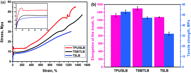 | ||
| Fig. 10 (a) Stress–strain curves of the specimens (the inset shows the enlarged part of the curves); (b) comparison of tensile strength and elongation at break among the specimens. | ||
4. Conclusions
TPU/PBS/PCL multicomponent materials with tunable phase continuity were designed and fabricated through layer-multiplying co-extrusion. The well-separated Tm's and Tc's of PCL and PBS endow the specimens with capacity to achieve TSME. The results revealed that the multilayer systems possessing continuous phase and numerous interfaces have larger Rf and Rr than those of the blend. In particular, TPU/SLB with a special multi-continuous structure exhibits the best TSME because of the high phase continuity of each domain and stronger interfacial shearing effect. Besides, the multi-continuous structure maximally integrates the mechanical performances of the components, resulting in an excellent balance of σs and εb. Hence, the current approach opens a new avenue for fabricating excellent TSMPs with optimal mechanical properties.Conflicts of interest
There are no conflicts of interest to declare.Acknowledgements
The authors are grateful to the National Natural Science Foundation of China (51873132, 51673136) for financial support of this work.References
- N. Zheng, Z. Z. Fang, W. W. Zou, Q. Zhao and T. Xie, Angew. Chem., Int. Ed., 2016, 55, 11421–11425 CrossRef CAS PubMed.
- Y. Q. Liu, K. G. Xu, Q. Chang, M. A. Darabi, B. J. Lin, W. Zhong and M. Xing, Adv. Mater., 2016, 28, 7758–7767 CrossRef CAS PubMed.
- Z. Li, X. Y. Zhang, S. Q. Wang, Y. Yang, B. Y. Qin, K. Wang, T. Xie, Y. Wei and Y. Ji, Chem. Sci., 2016, 7, 4741–4747 RSC.
- G. H. Yang, X. J. Wan, L. J. Liu, R. Li, Y. K. Su, X. R. Zeng and J. N. Tang, ACS Appl. Mater. Interfaces, 2016, 8, 34744–34754 CrossRef CAS PubMed.
- J. K. Deng, Z. Y. Chang, T. Zhao, X. D. Ding, J. Sun and J. Z. Liu, J. Am. Chem. Soc., 2016, 138, 4772–4778 CrossRef CAS PubMed.
- H. Meng, J. Zheng, X. F. Wen, Z. Q. Cai, J. W. Zhang and T. Chen, Macromol. Rapid Commun., 2015, 36, 533–537 CrossRef CAS PubMed.
- J. J. Li, Y. H. An, R. Huang, H. Q. Jiang and T. Xie, ACS Appl. Mater. Interfaces, 2012, 4, 598–603 CrossRef CAS PubMed.
- M. Zarek, M. Layani, I. Cooperstein, E. Sachyani, D. Cohn and S. Magdassi, Adv. Mater., 2016, 28, 4449–4454 CrossRef CAS PubMed.
- Y. Huang, N. Zheng, Z. Q. Cheng, Y. Chen, B. W. Lu, T. Xie and X. Feng, ACS Appl. Mater. Interfaces, 2016, 8, 35628–35633 CrossRef CAS PubMed.
- J. G. Hardy, M. Palma, S. J. Wind and M. J. Biggs, Adv. Mater., 2016, 28, 5717–5724 CrossRef CAS PubMed.
- Q. Zhao, H. J Qi and T. Xie, Prog. Polym. Sci., 2015, 49–50, 79–120 CrossRef CAS.
- M. Behl and A. Lendlein, Mater. Today, 2007, 10, 20–28 CrossRef CAS.
- N. Zheng, J. J. Hou, Y. Xu, Z. Z. Fang, W. K. Zou, Q. Zhao and T. Xie, ACS Macro Lett., 2017, 6, 326–330 CrossRef CAS.
- V. Schimpf, B. Heck, G. Reiter and R. Mülhaupt, Macromolecules, 2017, 50, 3598–3606 CrossRef CAS.
- J. Du, D. B. Lu, Z. L. Zhang, X. L. Yao, D. C. Wan, H. T Pu and Z. Lu, Polymer, 2018, 126, 206–210 CrossRef.
- L. Wang, X. F. Yang, H. M. Chen, T. Gong, W. B. Li, G. Yang and S. B. Zhou, ACS Appl. Mater. Interfaces, 2013, 5, 10520–10528 CrossRef CAS PubMed.
- T. Xie, Nature, 2010, 464, 267–270 CrossRef CAS PubMed.
- C. Samuel, S. Barrau, J. M. Lefebvre, J. M. Raquez and P. Dubois, Macromolecules, 2014, 47, 6791–6803 CrossRef CAS.
- J. J. Li and T. Xie, Macromolecules, 2011, 44, 175–180 CrossRef CAS.
- X. F. Luo and P. T. Mather, Adv. Funct. Mater., 2010, 20, 2649–2656 CrossRef CAS.
- M. Behl, I. Bellin, S. Kelch, W. Wagermaier and A. Lendlein, Adv. Funct. Mater., 2009, 19, 102–108 CrossRef CAS.
- J. Zotzmann, M. Behl, D. Hofmann and A. Lendlein, Adv. Mater., 2010, 22, 3424–3429 CrossRef CAS PubMed.
- S. K. Ahn and R. M. Kasi, Adv. Funct. Mater., 2011, 21, 4543–4549 CrossRef CAS.
- K. Suchao-in and S. Chirachanchai, ACS Appl. Mater. Interfaces, 2013, 5, 6850–6853 CrossRef CAS PubMed.
- Q. W. Zhang, H. Q. Wei, Y. J. Liu, J. S. Leng and S. Y. Du, RSC Adv., 2016, 6, 10233–10241 RSC.
- S. Chatani, C. Wang, M. Podgórski and C. N. Bowman, Macromolecules, 2014, 47, 4949–4954 CrossRef CAS.
- T. Xie, Polymer, 2011, 52, 4985–5000 CrossRef CAS.
- J. L. Hu, Y. Zhu, H. H. Huang and J. Lu, Prog. Polym. Sci., 2012, 37, 1720–1763 CrossRef CAS.
- H. Zhang, H. T. Wang, W. Zhong and Q. G. Du, Polymer, 2009, 50, 1596–1601 CrossRef CAS.
- E. Kurahashi, H. Sugimoto, E. Nakanishi, K. Nagata and K. Inomata, Soft Matter, 2012, 8, 496–503 RSC.
- S. M. Lai and Y. C. Lan, J. Polym. Res., 2013, 140, 2–8 Search PubMed.
- X. Jing, H. Y. Mi, H. X. Huang and L. S. Turng, J. Mech. Behav. Biomed. Mater., 2016, 64, 94–103 CrossRef CAS PubMed.
- H. J. Radusch, I. Kolesov, U. Gohs and G. Heinrich, Macromol. Mater. Eng., 2012, 297, 1225–1234 CrossRef CAS.
- S. M. Lai, P. Y. You, Y. T. Chiu and C. W. Kuo, J. Polym. Res., 2017, 24, 161 CrossRef.
- J. Zhao, M. Chen, X. Y. Wang, X. D. Zhao, Z. W. Wang, Z. M. Dang, L. Ma, G. H. Hu and F. H. Chen, ACS Appl. Mater. Interfaces, 2013, 5, 5550–5556 CrossRef CAS.
- B. D. Favis and D. Therrien, Polymer, 1991, 32, 1474–1481 CrossRef CAS.
- C. E. Scott and C. W. Macosko, Polymer, 1995, 36, 461–470 CrossRef CAS.
- J. K. Lee and C. D. Han, Polymer, 2000, 41, 1799–1815 CrossRef CAS.
- W. L. Gao, Y. Zheng, J. B. Shen and S. Y. Guo, ACS Appl. Mater. Interfaces, 2015, 7, 1541–1549 CrossRef CAS PubMed.
- J. M. Zhu, J. B. Shen, S. Y. Guo and H. J. Sue, Carbon, 2015, 84, 355–364 CrossRef CAS.
- B. S. Chen, W. L. Gao, J. B. Shen and S. Y. Guo, Compos. Sci. Technol., 2014, 93, 54–60 CrossRef CAS.
- L. F. Yi, S. S. Luo, J. B. Shen, S. Y. Guo and H. J. Sue, ACS Sustainable Chem. Eng., 2017, 5, 3063–3073 CrossRef CAS.
- S. S. Luo, Y. Zheng, Z. Zheng, H. Wu, J. B. Shen and S. Y. Guo, Chem. Eng. J., 2019, 355, 710–720 CrossRef CAS.
- S. S. Luo, L. F. Yi, Y. Zheng, J. B. Shen and S. Y. Guo, Eur. Polym. J., 2017, 89, 138–149 CrossRef CAS.
- L. F. Yi, Y. Xu, D. Li, J. B. Shen, S. Y. Guo and H. J. Sue, Ind. Eng. Chem. Res., 2018, 57, 4320–4328 CrossRef CAS.
- J. Du, S. R. Armstrong and E. Baer, Polymer, 2013, 54, 5399–5407 CrossRef CAS.
- S. R. Armstrong, J. Du and E. Baer, Polymer, 2014, 55, 626–631 CrossRef CAS.
- M. Michalak, M. Hakkarainen and A. C. Albertsson, ACS Sustainable Chem. Eng., 2016, 4, 129–135 CrossRef CAS.
- A. R. Costa-Pinto, V. M. Correlo, P. C. Sol, M. Bhattacharya, P. Charbord, B. Delorme, R. L. Reis and N. M. Neves, Biomacromolecules, 2009, 10, 2067–2073 CrossRef CAS PubMed.
- C. Zhang, X. Chen, G. T. Liu, H. Wu, J. Li, R. Chen and S. Y. Guo, RSC Adv., 2015, 5, 98999–99007 RSC.
- Y. Deng and N. L. Thomas, Eur. Polym. J., 2015, 71, 534–546 CrossRef CAS.
- W. Klairutsamee, P. Supaphol and I. Jangchud, J. Appl. Polym. Sci., 2015, 132, 42716 CrossRef.
- X. H. Wang, J. J. Zhou and L. Li, Eur. Polym. J., 2007, 43, 3163–3170 CrossRef CAS.
- M. F. Sonnenschein, S. J. Guillaudeu, B. G. Landes and B. L. Wendt, Polymer, 2010, 51, 3685–3692 CrossRef CAS.
- H. A. Khonakdar, S. H. Jafari, S. Rasouli, J. Morshedian and H. Abedini, Macromol. Theory Simul., 2005, 14, 428–434 CrossRef.
Footnote |
| † Electronic supplementary information (ESI) available: SEM pictures, DSC heating curves, calculated crystallization degrees, stress–strain curves. See DOI: 10.1039/c8ra08119k |
| This journal is © The Royal Society of Chemistry 2018 |

