 Open Access Article
Indirect fabrication of versatile 3D microfluidic device by a rotating plate combined 3D printing system†
Dong-Heon Ha‡
a,
Dong-Hyeon Ko‡ b,
Jin-oh Kim‡
 c,
Do Jin Im
 d,
Byoung Soo Kima,
Soo-Young Park
 e,
Steve Parkc,
Dong-Pyo Kim‡
 *b and
Dong-Woo Cho‡
 *a
*a
aDepartment of Mechanical Engineering, Pohang University of Science and Technology (POSTECH), Pohang, South Korea. E-mail: dwcho@postech.ac.kr
bDepartment of Chemical Engineering, Pohang University of Science and Technology (POSTECH), Pohang, South Korea. E-mail: dpkim@postech.ac.kr
cDepartment of Materials Science and Engineering, Korea Advanced Institute of Science and Technology (KAIST), Daejeon, Korea
dDepartment of Chemical Engineering, Pukyong National University, Busan, South Korea
eDepartment of Polymer Science and Engineering, Kyungpook National University, Daegu, South Korea
First published on 8th November 2018
Abstract
In the past decade, 3D-printing technology has been applied in the field of microfluidics to fabricate microfluidic devices for wide-ranging areas of study including chemistry, biology, medicine, and others. However, these methods face several limitations such as insufficient resolution and long fabrication time. In this study, versatile microfluidic devices with different functions were indirectly fabricated by a rapid sacrificial template printing process using a photocurable fluoropolymer with chemical durability. The Pluronic® F127 hydrogel as a sacrificial template was rapidly patterned on substrates by a non-lithographic printing process using a computer-controlled 3D-printing system. Viscous fluoropolymer was cast on the non-deformable template that was consequently removed by applying heat and negative pressure after UV curing. The chemical-resistant and transparent microchannels were oblate-hemispherical on the cross section. They were tested by performing a heterogeneous catalytic reaction as well as a photochemical reaction. The microchannels with controlled heights were devised to induce convection for functioning as a micromixer with asymmetric flows. Moreover, upon printing the Pluronic® F127 on both sides of the PFPE (perfluoropolyether–urethane dimethacrylate) membrane substrate, the 3D hybrid microfluidic device was embedded with a permeable membrane between the lower and upper channels, which is useful for gas–liquid chemical processes.
Introduction
A microreactor enables chemical reactions to be performed in a confined space several orders of magnitude smaller than conventional reactors. These downsizing effects with a high surface to volume ratio bring a number of attractive features such as fast mixing as well as accurate thermal and reaction time control, and accelerate reaction rates and improve yields. Moreover, the microfluidic devices can be designed for specific purposes and chemical processes. For example, application of the device to a multi-reaction integrated synthetic process which provides value-added chemicals may improve the process safety by limiting the exposure of the hazardous chemicals to the external environment and shorten the lead time from R&D to plant construction.1–4 In addition, gas–liquid processes in the dual-channel microfluidic systems achieved better diffusion behavior with no formation of random plugs that reduce contact area, when compared to routine single channel microreactors and falling reactors.5,6 Therefore, new conceptual microreactors with innovative goals may pose significant potential as ‘chemistry finders’ that must be repeatedly modified in response to feedback from chemical experiments.However, existing techniques (e.g., photolithography, soft lithography) generally involve time-consuming and labor-intensive steps to fabricate these devices. For example, channel heights are limited in photolithography-based fabrication technique, and photomask should be changed upon modification of the channel design. In the case of direct photolithography, fabrication time is long and the size of the microchannel is limited within the area exposed to UV.7–9 Besides, microfluidic devices with multi-dimensional and multifarious microstructures required highly sophisticated lithographic techniques such as multi-step lithography or grey-scale photolithography.10–13
Recently, various printing systems, including 3D printers, have facilitated the fabrication of microfluidic devices with either direct 3D-printing methods using commercially available resins,14,15 or indirect sacrificial printing methods using wax13,16 and hydrogel.17,18 The direct 3D-printing methods have demonstrated to fabricate diverse monolithic systems with sophisticated structural designs.14,15 However, the microfluidic channels with mostly millimeters scale exceeding the general size (ca. 500 μm) were achieved with rough surface morphology using limited amount of resin. On the other hand, the indirect sacrificial printing method has been widely attempted by various heterogeneous combinations of templates and matrix resin on various substrates.17 Yet, the indirect sacrificial template printing methods enabled to fabricate microfluidic devices only with simple channel designs mainly for biological uses.18 Therefore, rapid on-demand sacrificial printing techniques using suitable combinations of resin and sacrificial materials would be desirable to fabricate versatile and functional microfluidic devices with complex designs and chemical resistance, with no limitations of a special 3D-printing system and resin.
Here, we report a non-lithographic indirect fabrication method for multifarious microfluidic systems with a rapid on-demand sacrificial hydrogel printing (SHP) process and a photocurable fluoropolymer resin with chemical durability. The widths and heights for functional microchannels were simply varied with the printing speeds and heights of a 3D-printing system. The sequential casting of fluoropolymer matrix on the sacrificial hydrogel template and fast photo-curing consolidation step enabled to render the optically transparent microchannels with oblate-hemispherical cross section after neat removal of the template by applying mild vacuum. Moreover, the hybrid fluoropolymer-glass microfluidic device with high resistance to solvents and pressure was fabricated to devise a novel micromixer that induced internal convection flows in two splitting-merging microchannels with asymmetric dimension in height and width. Furthermore, the SHP technique was exploited to fabricate the alternative hybrid microfluidic system for gas–liquid process that was embedded with the gas-permeable membrane between the lower and upper channels. The serpentine and dual-channel microreactor was tested for a gas–liquid model reaction by vertically transporting a reactive NH3 gas in the lower channel into aqueous CuSO4 liquid in the upper channel.
Taken together, it is believed that this SHP technique is a useful platform approach to fabricate hybrid microfluidic devices by using various combinations of matrix resins and functional substrates for with multifarious purposes.
Materials and methods
Chemicals and materials
Perfluoropolyether–urethane dimethacrylate (PFPE, Fluoro MD 700), was purchased from Solvay-solexis and its photoinitiator 2-hydroxy-2-methyl-1-phenyl-propan-1-one (Darocur 1173) was purchased from BASF. Pluronic® F127 (F127) hydrogel (30 wt%, mixed with distilled water at 0 °C for 48 h) was used for sacrificial template. All chemicals and solvents were purchased from Sigma-Aldrich and used without further purification.Rotating plate combined 3D-printing system (RPPS)
RPPS, which is one-of-a-kind custom 3D-printing system, moves in the x and y directions, with two heads moving in the z-direction (Fig. 1a). Each head is equipped with a controllable heating unit (TCU-02, Musashi engineering Inc.) and a dispenser (ML-5000XII, Musashi engineering Inc.) providing tuneable pneumatic pressure up to 700 kPa, so that the molten material can be extruded through the nozzle (Fig. 1b). The system (HX2.0-MC, TURBO CNC Inc.) operates with G-code. A 200 mm × 200 mm workspace is used for making a channel by printing on a substrate such as glass slides. RPPS has a rotating motor which also functions as the rotating axis. In this experiment, a rotating motor was connected to the rotating plate (printing area: 25 × 100 mm) to which the membrane was loaded and fixed in the planar direction to enable the printing on both sides (Fig. 1c).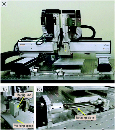 | ||
| Fig. 1 Rotating Plate combined 3D Printing System (RPPS) for printing microfluidic device. (a) A front view of RPPS, (b) heating unit and working space, (c) rotating plate. | ||
Indirect fabrication of microfluidic system by sacrificial template printing process
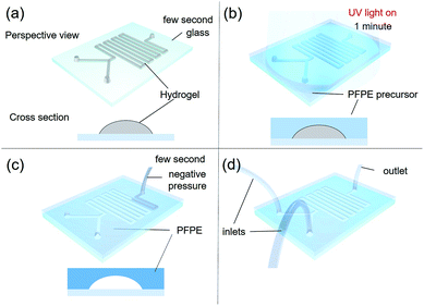
In general, a slide glass (S9213, 76 mm × 52 mm) was used as a substrate of the microfluidic device. In order to promote the adhesion between the glass and the PFPE fluoropolymer, the glass was chemically activated by applying plasma electrolytic oxidation to form hydroxyl groups. Then a 30 wt% solution of 3-trimethoxysilylpropyl methacrylate (MPTMS) in toluene was spin-coated at 3000 rpm for 30 s, annealed at 80 °C for 3 h, and washed with toluene to functionalize the glass surface with acrylate group that reacts with acrylate group of PFPE resin, as previously reported.19Sacrificial F127 was printed through a heated head at 50 °C on the functionalized glass substrates at room temperature (Fig. 2a; ESI S1†).20 The printed F127 patterns in height 100 μm (can be stacked up to several millimeters) and widths 100, 200, 300, 400 and 500 μm on glass were covered with 1 mm thickness of UV-curable PFPE precursor by spin-coating at 300 rpm for 10 s. Then the PFPE precursor was solidified by UV-irradiation for 1 min in N2 atmosphere (Fig. 2b). Inlet and outlet holes were made using a puncher (Uni-core 1.2 mm, Harris) at each end of PFPE/F127 composite patterns, and the F127 patterns was re-annealed at 0 °C for facile removal by employing vacuum suction (GLD-210B, ULVAC KIKO Inc.) through the holes (Fig. 2c and d), followed by washing the microchannel with pure water.
Preliminary test of the fabricated microfluidic devices
Solvent resistance was tested by comparing the weights of photo-cured PFPE and polydimethylsiloxane (PDMS) blocks (10 mm × 10 mm × 1 mm) between the as-prepared and the immersed in various solvents for 24 h, as previously reported.21 The pressure resistance of the PFPE and PDMS microfluidic devices (linear channel, length: 5 cm, height: 100 μm, widths: 100, 200, 300, 400 and 500 μm) were tested by measuring the burst pressures when a High-Performance Liquid Chromatography (HPLC) pump connected to an inlet and the outlet was blocked.21 Water was injected into the microchannel with an increasing flow rate in the range of 0.1 to 10 mL min−1 until leakage was observed. At that moment, the maximum pressure was determined as a measure of pressure resistance.For Suzuki coupling reaction, a flow was given to the microchannel in the device (single linear microchannel, width: 600 μm, height: 130 μm, length: 20 cm) using Piranha solution (H2SO4![[thin space (1/6-em)]](https://www.rsc.org/images/entities/char_2009.gif) :
:![[thin space (1/6-em)]](https://www.rsc.org/images/entities/char_2009.gif) H2O2 = 5
H2O2 = 5![[thin space (1/6-em)]](https://www.rsc.org/images/entities/char_2009.gif) :
:![[thin space (1/6-em)]](https://www.rsc.org/images/entities/char_2009.gif) 1, v/v) for a complete removal of F127 residues as well as to form hydroxyl groups on the glass substrate in the microchannel. Note that the PFPE part was not affected due to its high solvent resistance. For immobilization of metal catalyst, 30 wt% 3-aminopropyl triethoxysilane (APTES) in ethanol solution was passed through the microchannel to load Pd catalyst by serially infusing 10 mg Pd(II) acetate (Pd(OAc)2) in 10 mL ethanol solution.22,23 For the C–C coupling reaction, bromobenzonitrile (0.5 mmol) and phenylboronic acid (0.75 mmol) in a mixture of ethanol (3 mL) and distilled water (3 mL) solution was prepared, then potassium carbonate (1 mmol) was added. The mixed solution was infused at flow rate 3.3 μL min−1 into the Pd catalyst immobilized microchannel devices through single inlet using a syringe pump to yield a product. Secondly, the photochemical C–N coupling reaction with visible light was performed with a 30 W LED lamp placed 30 cm above the transparent fluoropolymer-glass microchannel (single linear microchannel, width: 600 μm, height: 130 μm, length: 20 cm). Note that both PFPE and glass have high transmittance to visible light.21 A mixture of (2E,7E)-1,9-diphenylnona-2,7-diene-1,9-dione 2-aminophenol (0.1 M) as a starting reagent, tris(2,2′-bipyridyl) dichlororuthenium(II) hexahydrate (5 mol%), lithium tetrafluoroborate (2 equiv.) and N,N-diisopropylethylamine (2 equiv.) dissolved in acetonitrile was injected at flow rate 1.65 μL min−1 into the microfluidic device. The collected product was immediately quenched in 1 mL of distilled water, then the desired products in crude solution were extracted with ether, and dried using a Rotavapor (R-210, BUCHI). The conversions of both reactions were measured by 1H NMR measurements (300 MHz, CDCl3, JEOL).
1, v/v) for a complete removal of F127 residues as well as to form hydroxyl groups on the glass substrate in the microchannel. Note that the PFPE part was not affected due to its high solvent resistance. For immobilization of metal catalyst, 30 wt% 3-aminopropyl triethoxysilane (APTES) in ethanol solution was passed through the microchannel to load Pd catalyst by serially infusing 10 mg Pd(II) acetate (Pd(OAc)2) in 10 mL ethanol solution.22,23 For the C–C coupling reaction, bromobenzonitrile (0.5 mmol) and phenylboronic acid (0.75 mmol) in a mixture of ethanol (3 mL) and distilled water (3 mL) solution was prepared, then potassium carbonate (1 mmol) was added. The mixed solution was infused at flow rate 3.3 μL min−1 into the Pd catalyst immobilized microchannel devices through single inlet using a syringe pump to yield a product. Secondly, the photochemical C–N coupling reaction with visible light was performed with a 30 W LED lamp placed 30 cm above the transparent fluoropolymer-glass microchannel (single linear microchannel, width: 600 μm, height: 130 μm, length: 20 cm). Note that both PFPE and glass have high transmittance to visible light.21 A mixture of (2E,7E)-1,9-diphenylnona-2,7-diene-1,9-dione 2-aminophenol (0.1 M) as a starting reagent, tris(2,2′-bipyridyl) dichlororuthenium(II) hexahydrate (5 mol%), lithium tetrafluoroborate (2 equiv.) and N,N-diisopropylethylamine (2 equiv.) dissolved in acetonitrile was injected at flow rate 1.65 μL min−1 into the microfluidic device. The collected product was immediately quenched in 1 mL of distilled water, then the desired products in crude solution were extracted with ether, and dried using a Rotavapor (R-210, BUCHI). The conversions of both reactions were measured by 1H NMR measurements (300 MHz, CDCl3, JEOL).
Splitting-merging type of micromixer fabrication with asymmetric flow
A micromixer system with total length 40 cm was composed of 9 sets of splitting and merging sub-channels, which induced asymmetric flow (two inlets 21.2 mm, larger main line 267.2 mm, and 8 smaller lines 109.3 mm). Sacrificial hydrogel template patterns consisting of two different widths and heights were individually printed using a 3D-printing system on the MPTMS-coated glass by adjusting printing speed. In the pattern for each sub-channel, the dimension of 500 μm wide and 170 μm high was made by 150 mm min−1 of printing speed, while the dimension of 200 μm wide and 50 mm high was obtained by 500 mm min−1 of printing speed. Eventually, a large microchannel of 500 μm width and 170 μm height (included 90° angle between 5 mm and 10 mm from splitting and merging point, respectively) and small microchannel of 200 μm width and 50 μm height (included a 135° angle between 5 and 7.1 mm from splitting and merging point, respectively) were mutually split and merged along 8 cycles, which were initiated through two inlet streams (10.6 mm length for each, 500 μm width and 170 μm height). In addition, the fabrication conditions such as fluoropolymer casting, photo-curing, and template removal were identical as aforementioned. The mixing efficiency was evaluated by flowing two immiscible solutions of methanol (50%, v/v) and n-heptane at flow rates at ranges 40 μL min−1 to 200 μL min−1. The transferred concentration of Nile red dye initially dissolved only in methanol to n-heptane was quantified using a UV-Vis transmittance spectrum at wavelengths from 380 to 780 nm.24 For comparison, a Y-shaped and serpentine microchannel with a rectangular cross section 500 μm wide, 170 μm high and 234.5 mm long was fabricated on glass by conventional photo-lithography technique and fluoropolymer resin, but similarly designed with the micromixer in cross sectional area and inner volume.Membrane embedded dual-channel microreactor
Polytetrafluoroethylene (PTFE) membrane filter paper (pore size: 0.5 μm, diameter: 47 mm, Whatman) was used as a printing substrate with moderate flatness. 30 wt% F127 hydrogel was printed by 400 mm min−1 of printing speed to make a serpentine pattern (300 μm wide, 110 μm high and 18 cm long). Then, the mirrored template pattern was printed on the opposite side of the membrane after careful alignment with aid of mark on side of the membrane and printing stage, followed by identical casting and photo-curing of fluoropolymer and template removal as mentioned previously. Eventually, a dual-channel microfluidic system embedded with PTFE membrane was used as a gas–liquid microreactor by reacting a 10 wt% CuSO4 aqueous solution with NH3 gas. The NH3 gas was generated by heating a 28–30% NH3 aqueous solution at 40 °C. Residence time was adjusted to 10, 20, 30 and 40 s by controlling flow rates. Unreacted NH3 gas was quenched by collecting with water. UV-Vis absorbance spectrum of product at wavelength 600 nm (yellow region) was measured at different residence time to monitor the gas–liquid reaction.Results and discussion
Rapid sacrificial template printing process
The printing speed, nozzle size and extrusion pressure is an important factor to control the resulting channel widths. In general, the higher printing speed produced the narrower width of microchannels. The 27G nozzle with 200 kPa formed 120–600 μm width patterns at 1000–50 mm min−1 of printing speed, respectively. The 27G nozzle with 400 kPa gave 260–980 μm width patterns at 1000–50 mm min−1 of printing speed, respectively (Fig. 3).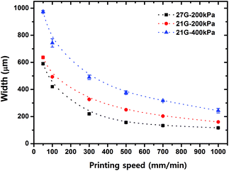 | ||
| Fig. 3 Relationship between printing speed, extrusion pressure, nozzle size and resulting pattern width of the sacrificial template. | ||
In addition, the pattern height can be adjusted by controlling the printing height, a distance between the nozzle and the printing surface. It indicates that this SHP technique allowed reproducible production of microchannels with specified height as well as width. For example, the microchannels with a width of 600 μm and a height of 130 μm were made by printing at 300 mm min−1 using 30 wt% F127 hydrogel. Note that there was no observable difference in dimensions between the obtained microchannel and the F127 pattern (width and height).
Eventually, the SHP process enabled successful fabrication of Y-shaped microchannels consistent with the initial CAD design as shown in Fig. 4a and b. Thus, these microchannels are well ready to use for chemical reactions that require precise control of flow dynamics.
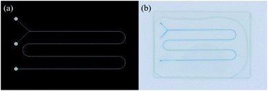 | ||
| Fig. 4 CAD design and corresponding optical image of the Y-shaped microchannel. (width: 600 μm, height: 130 μm). | ||
Preliminary test of the fabricated microfluidic devices
As expected, the fluoropolymer PFPE showed superior solvent resistance with a lower swelling ratio in most organic solvents even at 60 °C to the PDMS. In the pressure resistance tests of hybrid PFPE-glass microfluidic devices (linear length 5 cm), the microchannels with various dimensions (height 100 μm, widths 100–500 μm), were burst at 670 psi, which is much higher than 270 psi of the hybrid PDMS-glass channel. This stronger adhesion is attributed to a chemical bond between the glass surface functionalized with acrylate group and the PFPE resin containing acrylate groups, as similarly reported.19 Thus, the hybrid PFPE-glass microchannels are suitable for chemical reactions at high flow rates that endure the induced high pressure on the walls of the microchannel.To test the effectiveness of the hybrid PFPE-glass microfluidic device as a catalytic microreactor (width: 600 μm, height: 130 μm, length: 20 cm), two typical chemical reactions such as Suzuki coupling in the presence of immobilized palladium (Pd) catalyst, and photochemical C–N coupling under visible light were performed. For Suzuki coupling, the immobilized Pd(OAc)2 catalyst on the amine functionalized glass surface was confirmed by Attenuated Total Reflection (ATR) spectroscopy (Fig. S1†).23 The hydroxylated surface of glass by Piranha solution was further modified by amine using APTES reagent, where newly appeared a peak at 2900 cm−1 corresponding to the amine group. A reagent mixture of bromobenzonitrile and phenylboronic acid of ethanol solution with potassium carbonate additive flowed into the Pd-immobilized single-line serpentine microchannel (Fig. S2a†). The reaction for 5 min at room temperature has resulted in 100% conversion and 99% yield of 4-phenylbenzonitrile product (Fig. S3†), which is more efficient than the conventional flask reactions taken several hours.25–28 For photochemical C–N coupling in the optically transparent hybrid PFPE-glass microfluidic device as used for the Suzuki reaction, 100% conversion and 81% yield of (1R,5S,6R,7S)-bicyclo[3.2.0]heptane-6,7-diylbis(phenyl-methanone) product was obtained by 10 min reaction time at room temperature (Fig. S2b and S4†), while the conventional bulk reaction produced similar results at extended reaction times.21,29,30 These results indicate that the microfluidic device fabricated by the SHP process enabled to perform various organic reactions with high reliability, which is comparable to the capillary microreactors.
Splitting-merging type of micromixer with asymmetric flow
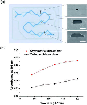
The micromixer is an important component in microfluidic platforms for complex chemical reactions and biological applications.31 In particular, it is well documented that serial lamination during dynamic flows efficiently promoted the mixing efficiency, in which two laminar flows were forced to merge at the horizontal and vertical direction in a serial manner.32–34 However, they inevitably required sophisticated fabrication techniques such as multi-level stacking of microstructures.30In this work, a new micromixer system, composed of 8 sets of splitting and merging sub-channels with different heights and widths, was readily fabricated by the SHP process using a 3D-printing system (Fig. S5a†). A large microchannel (width: 500 μm, height: 170 μm, degree: 90°) and a small microchannel (width: 200 μm, height: 50 μm, degree: 48°) were continuously split and merged at 8 cycles, which were initiated through two inlet streams and collected at one outlet (Fig. 5a). Following the channel design, each solution must alternatingly flow through the large channel and the small channel in the cyclic diverging and converging manner along 236 mm in average channel length (total length 40 cm) (Fig. S5a†). This asymmetric microchannel design induced convection flow for functioning as an efficient micromixer.35 In particular, when two immiscible liquids of 50 vol% methanol (0.93 g mL−1) and n-heptane (0.68 g mL−1) with a big difference in the density were used as upstream flow, the local convection flow could be enhanced to balance its density difference. The mixing efficiency was determined by measuring the concentration of Nile red dye dissolved in n-heptane that was transferred from methanol at various flow rates in range 40–200 μL min-1. In order to compare the mixing efficiency, the conventional Y-shaped serpentine microchannel was fabricated with similar structural parameters (500 μm wide, 170 μm high and 234.5 mm long) except for rectangular cross sectional shape (Fig. S5b†). Both micromixers have the same inner volume as 14.07 μL and same cross sectional area as 0.06 mm2. The maximum UV-Vis absorbance at 498 nm wavelength was plotted against flow rates (Fig. S5c† and 5b). In general, the mixing efficiency linearly increased with increasing flow rates and reached its maxima at 200 μL min−1. Moreover, the splitting-merging type of micromixer revealed significantly superior mixing efficiency to the Y-shaped serpentine microchannel at the entire flow rates. The absorbance was about 33.6% higher for splitting-merging micromixer than those for Y-shaped micromixer. Overall, these results demonstrated that the rapid SHP technique is a very useful platform to fabricate an asymmetric flow micromixer with sophisticated design by applying different printing speeds to a 3D-printing system.
Fabrication of 3D dual-channel using rotating plate
Rotating plate of RPPS is one of the unique component compared with any other commercialized 3D-printing system. Commercialized 3D-printing system only provides an upper surface of bed, but rotating plate enables the printing on both side.In this study, PTFE membrane was fixed on the rotating plate and sacrificial template was printed in a lattice form (width: 600 μm, height: 400 μm) on one side and in helix (line width: 300 μm, height: 600 μm) on the other side. The sacrificial template printed PTFE membrane was unloaded from the rotating plate and was filled with PFPE. After crosslinking of PFPE, 3D dual-channel was fabricated (Fig. 6).
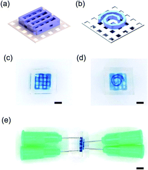 | ||
| Fig. 6 (a and b) Upper and bottom CAD image of 3D dual-channel. (c–e) top, bottom, side view of 3D dual-channel (scale bar: 2.5 mm). | ||
Membrane embedded dual-channel microreactor
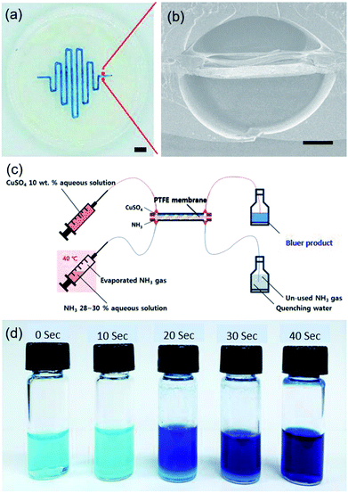
Sacrificial template printing can be further applied to fabricate alternative functional microfluidic device embedded with a gas permeable membrane. The serpentine patterns of F127 template were printed on both sides of the PTFE membrane substrate after aforementioned careful alignment (ESI Movie S2†). In this step, the hydrophilic F127 could not infiltrate the hydrophobic PTFE membrane pores, where remained white colour due to light scattering effect (Fig. S6a†). However, it was differently observed that the hydrophobic PFPE resin could readily fill the PTFE membrane pores and became optically transparent (Fig. S6a–c†). The PFPE filling the gap between the channels is very crucial to block the unwanted lateral diffusion and cross-leakage of gas and liquid reagents across the parallel microchannels. Therefore, the constructed serpentine dual-channel (width: 400 μm, height: 300 μm, internal lateral angle: 120°, length: 18 cm) on the embedded PTFE filter membrane could allow vertical permeation of gas and hydrophobic liquids across the membrane (Fig. 7a and b).To demonstrate the feasibility of a PTFE membrane-embedded dual-channel as a microreactor for gas–liquid reaction, a 10 wt% CuSO4 aqueous solution was reacted with NH3 gas diffused through PTFE membrane from opposite channel (Fig. 7c). As the initial CuSO4 was successfully converted to [Cu(NH3)4(H2O)n]SO4 complex by ligand change, the solution became deep blue from pale blue (Fig. 7d).36 UV-Vis absorbance spectrum at 600 nm wavelength increased with increasing residence time (Fig. S6d†). The increase in yellow absorbance indicated the increase of blueness due to the complementary color, consistent with the reaction performance, as expected. Note that the printing capability of various patterns on alternative moderately flat substrates enables to devise functional microfluidic systems.
Conclusions
A non-lithographic indirect fabrication method using a Rotating Plate combined 3D-printing System for sacrificial template printing has been demonstrated to fabricate multifarious and resistant 3D microfluidic systems, followed by casting and photo-curing of fluoropolymer and template removal steps. The low-cost production process takes only a few minutes, which is far less than alternative fabrication methods. These hybrid fluoropolymer-glass microfluidic chips were designed to perform versatile functions as catalyst-immobilized and photochemical organic microreactors, an asymmetric micromixer and a PTFE membrane embedded dual-channel microreactor for gas–liquid reaction. In particular, a novel asymmetric splitting-merging micromixer with internal convection flows was devised by varying channel dimensions using 3D-printing technology. We have also shown a successful indirect fabrication of 3D dual-channel using rotating plate. Furthermore, the membrane embedded dual-channel fabricated for gas–liquid reaction was successfully used for vertical diffusion of reactive NH3 gas into the CuSO4 liquid channel with no cross-leakage between paralleled channels. Therefore, it is plausible that this sacrificial hydrogel template printing method may be competitive to 3D-printing technologies as well as lithographic fabrication techniques. As the channel of the microfluidic system fabricated through this technology has a different cross-section dimension compared from the conventional channel, there lies a possibility of the difference in fluid flow from the existing one as well. Still, the extension to 3D-printing technology provides synergic opportunities to microfluidics with complex designs and also has numerous potential applications in other fields.Conflicts of interest
There are no conflicts to declare.Acknowledgements
This study was supported by the National Research Foundation of Korea (NRF) grant funded by the Korean government (MSIP) (no. 2010-0018294) and (no. 2017R1A3B1023598).Notes and references
- R. A. Maurya, C. P. Park, J. H. Lee and D. P. Kim, Angew. Chem., Int. Ed., 2011, 50, 5952–5955 CrossRef CAS PubMed.
- K. C. Basavaraju, S. Sharma, R. A. Maurya and D. P. Kim, Angew. Chem., Int. Ed., 2013, 52, 6735–6738 CrossRef CAS PubMed.
- S. Sharma, R. A. Maurya, K. I. Min, G. Y. Jeong and D. P. Kim, Angew. Chem., Int. Ed., 2013, 52, 7564–7568 CrossRef CAS PubMed.
- K. S. Elvira, X. C. I. Solvas, R. C. R. Wootton and A. J. deMello, Nat. Chem., 2013, 5, 905–915 CrossRef CAS PubMed.
- C. P. Park, R. A. Maurya, J. H. Lee and D. P. Kim, Lab Chip, 2011, 11, 1941–1945 RSC.
- W. Li, K. Liu, R. Simms, J. Greener, D. Jagadeesan, S. Pinto, A. Gunther and E. Kumacheva, J. Am. Chem. Soc., 2012, 134, 3127–3132 CrossRef CAS PubMed.
- J. P. Rolland, R. M Van Dam, D. A. Schorzman, S. R. Quake and J. M. DeSimone, J. Am. Chem. Soc., 2004, 126, 2322–2323 CrossRef CAS PubMed.
- A. Vitale, M. Quaglio, S. L. Marasso, A. Chiodoni, M. Cocuzza and R. Bongiovanni, Direct Photolithography of Perfluoropolyethers for Solvent-Resistant Microfluidics, Langmuir, 2013, 29, 15711–15718 CrossRef CAS PubMed.
- A. Vitale, M. Quaglio, A. Chiodoni, K. Bejtka, M. Cocuzza and C. F. Pirri, et al., Oxygen-Inhibition Lithography for the Fabrication of Multipolymeric Structures, Adv. Mater., 2015, 27, 4560–4565 CrossRef CAS PubMed.
- C. C. Chen, D. Hirdes and A. Folch, Proc. Natl. Acad. Sci. U. S. A., 2003, 100, 1499–1504 CrossRef CAS PubMed.
- C. M. Waits, B. Morgan, M. Kastantin and R. Ghodssi, Sens. Actuators, A, 2005, 119, 245–253 CrossRef CAS.
- K. Totsu, K. Fujishiro, S. Tanaka and M. Esashi, Sens. Actuators, A, 2006, 130, 387–392 CrossRef.
- V. Dragone, V. Sans, M. H. Rosnes, P. J. Kitson and L. Cronin, Beilstein J. Org. Chem., 2013, 9, 951–959 CrossRef CAS PubMed.
- K. B. Anderson, S. Y. Lockwood, R. S. Martin and D. M. Spence, Anal. Chem., 2013, 85, 5622–5626 CrossRef CAS PubMed.
- D. Therriault, S. R. White and J. A. Lewis, Nat. Mater., 2003, 2, 265–271 CrossRef CAS PubMed.
- C. J. Hansen, W. Wu, K. S. Toohey, N. R. Sottos, S. R. White and J. A. Lewis, Adv. Mater., 2009, 21, 4143–4147 CrossRef CAS.
- L. E. Bertassoni, M. Cecconi, V. Manoharan, M. Nikkhah, J. Hjortnaes, A. L. Cristino, G. Barabaschi, D. Demarchi, M. R. Dokmeci, Y. Z. Yang and A. Khademhosseini, Lab Chip, 2014, 14, 2202–2211 RSC.
- D. B. Kolesky, R. L. Truby, A. S. Gladman, T. A. Busbee, K. A. Homan and J. A. Lewis, Adv. Mater., 2014, 26, 3124–3130 CrossRef CAS PubMed.
- A. Vitale, M. Quaglio, M. Cocuzza, C. F. Pirri and R. Bongiovanni, Eur. Polym. J., 2012, 48, 1118–1126 CrossRef CAS.
- J. Y. Kim, E. K. Park, S. Y. Kim, J. W. Shin and D. W. Cho, J. Micromech. Microeng., 2009, 19, 104003 Search PubMed.
- J. O. Kim, H. Kim, D. H. Ko, K. I. Min, J. Im do, S. Y. Park and D. P. Kim, Lab Chip, 2014, 14, 4270–4276 RSC.
- Z. Y. Xiao, Y. Zhao, A. J. Wang, J. Perumal and D. P. Kim, Lab Chip, 2011, 11, 57–62 RSC.
- X. D. Le, Z. P. Dong, Y. S. Liu, Z. C. Jin, T. D. Huy, M. Le and J. T. Ma, J. Mater. Chem. A, 2014, 2, 19696–19706 RSC.
- S. Panic, S. Loebbecke, T. Tuercke, J. Antes and D. Boskovic, Chem. Eng. J., 2004, 101, 409–419 CrossRef CAS.
- Z. G. Zhou, M. Y. Liu, X. L. Wu, H. W. Yu, G. H. Xu and Y. R. Xie, Appl. Organomet. Chem., 2013, 27, 562–569 CAS.
- A. Kumar, G. K. Rao, F. Saleem, R. Kumar and A. K. Singh, J. Hazard. Mater., 2014, 269, 9–17 CrossRef CAS PubMed.
- N. Fukaya, M. Ueda, S. Onozawa, K. K. Bando, T. Miyaji, Y. Takagi, T. Sakakura and H. Yasuda, J. Mol. Catal. A: Chem., 2011, 342–43, 58–66 CrossRef.
- P. H. Li, L. Wang, L. Zhang and G. W. Wang, Adv. Synth. Catal., 2012, 354, 1307–1318 CrossRef CAS.
- L. C. Wang, H. Y. Jang, Y. Roh, V. Lynch, A. J. Schultz, X. P. Wang and M. J. Krische, J. Am. Chem. Soc., 2002, 124, 9448–9453 CrossRef CAS PubMed.
- T. G. Baik, A. L. Luis, L. C. Wang and M. J. Krische, J. Am. Chem. Soc., 2001, 123, 6716–6717 CrossRef CAS PubMed.
- N. T. Nguyen and Z. G. Wu, J. Micromech. Microeng., 2005, 15, R1–R16 CrossRef.
- B. L. Gray, D. Jaeggi, N. J. Mourlas, B. P. van Drieenhuizen, K. R. Williams, N. I. Maluf and G. T. A. Kovacs, Sens. Actuators, A, 1999, 77, 57–65 CrossRef CAS.
- M. S. Munson and P. Yager, Anal. Chim. Acta, 2004, 507, 63–71 CrossRef CAS.
- N. Schwesinger, T. Frank and H. Wurmus, J. Micromech. Microeng., 1996, 6, 99–102 CrossRef CAS.
- D. S. Kim, S. H. Lee, T. H. Kwon and C. H. Ahn, Lab Chip, 2005, 5, 739–747 RSC.
- Y. Zhao, M. L. Qin, A. J. Wang and D. Kim, Adv. Mater., 2013, 25, 4561–4565 CrossRef CAS PubMed.
Footnotes |
| † Electronic supplementary information (ESI) available: Movie of the ultra-fast fabrication of microfluidic device and fabrication of dual channel, table of solvent and pressure resistance, figure of controlled chip lengths, ATR spectrum of surface modification steps, 1H-NMR spectrum Image of PFPE membrane dual channel. See DOI: 10.1039/c8ra08465c |
| ‡ Dong-Heon Ha, Dong-Hyeon Ko, Jin-Oh Kim, Dong-Woo Cho and Dong-Pyo Kim equally contributed to this work. |
| This journal is © The Royal Society of Chemistry 2018 |

