 Open Access Article
A promising bulky anion based lithium borate salt for lithium metal batteries†
Lixin
Qiao
ab,
Zili
Cui
*b,
Bingbing
Chen
b,
Gaojie
Xu
b,
Zhonghua
Zhang
b,
Jun
Ma
b,
Huiping
Du
b,
Xiaochen
Liu
b,
Suqi
Huang
c,
Kun
Tang
ab,
Shanmu
Dong
b,
Xinhong
Zhou
*a and
Guanglei
Cui
 *b
*b
aCollege of Chemistry and Molecular Engineering, Qingdao University of Science & Technology, Qingdao, 266042, P. R. China. E-mail: zxhhx2008@163.com
bQingdao Industrial Energy Storage Research Institute, Qingdao Institute of Bioenergy and Bioprocess Technology, Chinese Academy of Sciences, Qingdao, 266101, P. R. China. E-mail: cuigl@qibebt.ac.cn; Tel: +86-532-80662746
cSchool of Chemistry and Chemical Engineering, Qingdao University, Qingdao, 266071, P. R. China
First published on 1st March 2018
Abstract
A new salt of lithium trifluoro(perfluoro-tert-butyloxyl)borate (LiTFPFB) which possesses a bulky fluoroalkoxyl functional group in the borate anion has been synthesized for high energy lithium metal batteries. The presence of the bulky fluoroalkoxyl group in the borate anion of LiTFPFB can facilitate ion dissociation and in situ generate a protective film on the Li anode. As a result, LiTFPFB possesses a dramatically improved ionic conductivity and LiFePO4/Li cells using 1.0 M LiTFPFB/PC electrolyte exhibit improved capacity retention especially upon cycling at elevated temperature (60 °C). Ex situ surface analysis reveals that a protective film is formed on the lithium metal anode, which can inhibit further decomposition of the electrolyte. Furthermore, the LiTFPFB based electrolyte also imparts an excellent cycling performance to LiCoO2/Li metal cells for 500 cycles. The outstanding performance of the LiTFPFB salt demonstrates that it is a very promising baseline salt for next generation lithium metal batteries.
1. Introduction
Current Li-ion batteries (LIBs) are widely used for portable electronics, electric vehicles, and stationary grid-energy storage devices.1,2 The salt in LIBs plays a critical role in battery performance, being the primary source of free conducting lithium ions, and also mediates the formation of a solid electrolyte interface (SEI) at the electrodes. To date, LiPF6 has been the most commonly used salt for commercial LIBs due to its optimum combination of ionic conductivity, electrochemical window, and electrode interfacial properties.3 However, the large-scale application of LiPF6 has raised safety concerns due to its poor chemical and thermal stability in lithium ion batteries, especially for the promising lithium metal batteries.2 LiBF4 (shown in Scheme 1) is well known for its superior thermal stability, non-corrosivity to the Al current collector, and improved low temperature performance arising from reduced charge-transfer resistance.4,5 However, it is rarely used as a baseline salt in lithium ion batteries because of the unsatisfactory ionic conductivity resulting from the low dissociation degree arising from strong coulombic interactions between the anion and the lithium ion.6The introduction of a bulky electron-withdrawing group into the anion has been considered as one of the most promising strategies for improving the ionic conductivity of the lithium salt due to its weak coulombic interactions.7,8 For example, Ue and coworkers prepared lithium pentafluoroethyltrifluoroborate (LiFAB) by substituting one F− in LiBF4 by a bulky fluoric group.9 The ionic conductivity of 1.0 M LiFAB in EC/EMC (30![[thin space (1/6-em)]](https://www.rsc.org/images/entities/char_2009.gif) :
:![[thin space (1/6-em)]](https://www.rsc.org/images/entities/char_2009.gif) 70 vol%) reaches 8.0 × 10⁻⁴ S cm−1 at room temperature, which is twofold higher than that of LiBF4 (3.6 × 10⁻⁴ S cm−1). However, LiFAB displays worse oxidation stability than LiBF4 and deteriorated battery performance at elevated temperature (higher than 60 °C). Alternatively, Zhang synthesized lithium difluoro(oxalate)borate (LiDFOB) by using one oxalate anion to substitute two F− in LiBF4.10 The ionic conductivity is enhanced and simultaneously a stable SEI is formed on the graphite anode. However, LiDFOB is less thermally stable than LiBF4.10
70 vol%) reaches 8.0 × 10⁻⁴ S cm−1 at room temperature, which is twofold higher than that of LiBF4 (3.6 × 10⁻⁴ S cm−1). However, LiFAB displays worse oxidation stability than LiBF4 and deteriorated battery performance at elevated temperature (higher than 60 °C). Alternatively, Zhang synthesized lithium difluoro(oxalate)borate (LiDFOB) by using one oxalate anion to substitute two F− in LiBF4.10 The ionic conductivity is enhanced and simultaneously a stable SEI is formed on the graphite anode. However, LiDFOB is less thermally stable than LiBF4.10
On the other hand, the fluoroalkoxyl functional group, usually existing in fluoric carbonate solvent, can decompose and in situ form an elastomeric polymeric matrix SEI on graphite,11 lithium silicon alloys,12 and Li metal surfaces.13 The as-formed SEI can effectively suppress Li dendrite growth and inhibit further decomposition of the electrolyte,11 making the fluoroalkoxyl functional group very attractive for next generation high energy lithium metal batteries. It is also noted that the introduction of the fluoroalkoxyl group into a lithium or/and magnesium salt anion can significantly improve the oxidation stability of the salt, as observed in Long's14 and our previous studies.15 However, to the best of our knowledge, there are relatively few studies devoted to the introduction of the electron-withdrawing fluoroalkoxyl group into the lithium salt anion to protect the lithium metal anode.
Herein, we for the first time intend to introduce a bulky fluoroalkoxyl functional group to substitute one F− in LiBF4 inspired by the aforementioned advantages of the fluoroalkoxyl group in ionic conductivity and oxidation stability improvement as well as its function in lithium metal protection. As a result, a novel lithium salt, namely the trifluoro(perfluoro-tert-butyloxyl)borate (LiTFPFB) salt (shown in Scheme 1), has been synthesized by a one-step reaction. The effective species of the salt have been analyzed by high resolution mass spectrometry (HR-MS), and 7Li, 11B and 19F NMR. The stability of the LiTFPFB salt to the Al current collector as well as the ionic conductivities has been studied. Moreover, the elevated temperature (60 °C) battery performance of LiFePO4/Li cells and high-voltage performance of LiCoO2/Li cells have also been studied to investigate the feasibility of the salt in high energy lithium metal batteries. Finally, the morphologies and compositions of the cycled Li metal were investigated by SEM imaging and XPS methods to elucidate the compatibility between the LiTFPFB based electrolyte and the lithium metal anode.
2. Results and discussion
2.1. DFT computations
To screen a suitable lithium salt with both high oxidation stability and high dissociation degree, DFT calculation was conducted at the B3LYP/6-31G(p,d)* level with respect to different anion substituted lithium borates, i.e. LiDFOB, Li[RFOBF3] (RF = fluoroalkyl) and LiBF4. Two kinds of fluoroalkoxyl substituted lithium borates, Li[(CF3)2CHOBF3] and Li[(CF3)3COBF3] (LiTFPFB), were designed, and the energy (in eV) of the highest occupied molecular orbital (HOMO) and the lowest unoccupied molecular orbital (LUMO) as well as dissociation energy were calculated compared to traditional LiBF4 and LiDFOB (shown in Table 1). It is possible to estimate the oxidative stability of the molecule from the calculated HOMO energies, as the oxidation reaction involves an electron loss from its HOMO energy level.16 The values listed here were calculated for the structure optimized species. As predicted, the lower the HOMO energy level is, the greater is the expected stability against oxidation. Of the four anions, TFPFB− exhibits the best oxidation stability with the lowest HOMO of −4.64 eV, while BF4− shows the second best value of −4.53 eV, making them much more stable than DFOB− (−3.60 eV). With respect to the dissociation energy, the LiTFPFB salt possesses the lowest value of 251.5 kJ mol−1, which is only one-half that of the other three, and thus is highly expected to have an improved ionic conductivity. Based on the calculation results, LiTFPFB with excellent oxidation stability and the lowest dissociation energy was picked out as the optimal lithium salt for further investigation.2.2. Synthesis and characterization of LiTFPFB
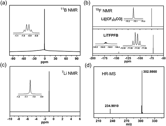
The LiTFPFB salt was obtained by a one-step reaction of lithium perfluoro-tert-butoxide (Li[(CF3)3CO]) with (C2H5)2O·BF3 in THF (see Scheme S1 in the ESI†). The successful preparation of LiTFPFB is confirmed using 7Li, 11B, and 19F NMR and HR-MS spectra (Fig. 1 and S1 and S2†). In the 11B spectrum, the characteristic peaks at −0.92 ppm are ascribed to the –O–BF3 group. Remarkable differences between the 19F NMR spectra of the reactant Li[(CF3)3CO] (one peak at −75.13 ppm) and the product LiTFPFB (two peaks at −71.92 and −144.71 ppm) are also well observed. Besides, HR-MS presents further convincing data on the structure in the mass spectrum of LiTFPFB. The peaks at m/z 234.9810 and 302.9860 are assigned to [(CF3)3CO]− and TFPFB−, respectively, and the peak at m/z 234.9810 might have resulted from the fragment ions of TFPFB− in the mass spectrometer. The disappearance of the Li[(CF3)3CO] species signal in the 19F NMR spectra (Fig. 1b) confirms the total conversion of reactants. Therefore, it is concluded that LiTFPFB is successfully synthesized in this study.2.3. Ionic conductivity and electrochemical properties
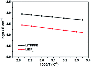
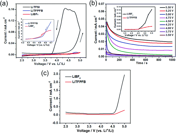
Fig. 2 compares the temperature dependent ionic conductivity of the LiTFPFB salt and LiBF4 in PC solvent. Both the electrolytes show a typical Arrhenius-type correlation from 25 to 80 °C. The ionic conductivities of 1.0 M LiTFPFB/PC were 5.4 × 10⁻⁴ S cm−1 at 25 °C and 1.1 × 10⁻³ S cm−1 at 80 °C, respectively. The activation energy was calculated to be 11.17 kJ mol−1, which is lower than that of LiBF4 (12.64 kJ mol−1). In the whole temperature range, the ionic conductivity of the LiTFPFB based electrolyte is about three times higher than that of LiBF4. This result confirms that the bulky anion TFPFB− is beneficial for the delocalization of the lithium salt, which can lower the dissociation energy and thus enhance the ionic conductivity.17 These findings are well in accordance with the DFT results (Table 1). As a result of the low mobility of the larger anion size, the lithium-ion transference number can attain a value of 0.48 (shown in Fig. S3†), which is superior to that of the classical LiBF4 salt (tLi+ = 0.30).18The compatibility of LiTFPFB with the Al current collector was characterized by cyclic voltammetry compared with LiBF4. As a reference, the fluoroalkyl-containing salt lithium bis(trifluoromethane-sulphonyl)imide (LiTFSI) in PC solvent was also evaluated (Fig. 3a). For the LiTFSI based electrolyte, the current increases markedly when the applied potential exceeds 4.5 V vs. Li+/Li and persists during the negative sweep down to 3.7 V. Hysteresis in the cyclic voltammogram is an indicator of Al corrosion, which is consistent with the result obtained by Evans et al.19 The low corrosion potential of Al at around 3.7 V may be due to the strong interaction between TFSI− and the cation in the passivation film of Al, which may lead to higher solubility of the passivation species. In sharp contrast, the corresponding current responses of LiBF4 and LiTFPFB electrolytes are much smaller than that of LiTFSI. Furthermore, the cathodic current of the LiTFPFB based electrolyte is smaller than that of LiBF4, as shown in the inset of Fig. 3a. These results indicate that LiTFPFB possesses the best compatibility with the Al current collector among the three measured salts. Moreover, chronoamperometry was further used to evaluate the compatibility of LiBF4 and LiTFPFB with Al (Fig. 3b and S4†).20,21 As depicted in Fig. 3b, the initial rapid decrease of the anodic current on a fresh Al surface indicates instant formation of the passivation layer.22 The LiTFPFB based cell shows no sign of corrosion until the potential reaches ca. 4.5 V, which is consistent with the CV results described above, indicating enhanced Al current collector stability up to 4.5 V versus Li+/Li.21 In addition, the corrosion current collected at t = 103 s vs. the applied potential is plotted in the inset of Fig. 3b. It is noted that the LiTFPFB based electrolyte shows lower current density than that of LiBF4 even above 4.5 V. These results indicate that the LiTFPFB based electrolyte is more compatible with the Al current collector than that of LiBF4.
The oxidation behaviors of both electrolytes were investigated by linear sweep voltammetry (LSV) using Pt as the working electrode. As shown in Fig. 3c, the anodic current of the LiBF4 based electrolyte is very low below 4.5 V (vs. Li+/Li) and then increases distinctly when the voltage exceeds 4.6 V corresponding to the known electrolyte decomposition.23 For the LiTFPFB based electrolyte, the initial oxidation potential is observed at 4.5 V, followed by a slight increase. All these observations above verify that the oxidation decomposition of the electrolyte can be effectively suppressed and the Al current collector can be well passivated with LiTFPFB, which is well in agreement with the calculation result (Table 1).
2.4. Performance of lithium metal batteries (LMBs)
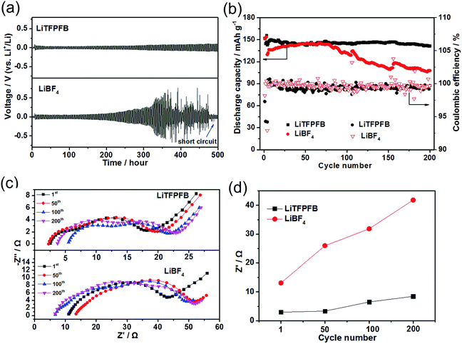
Polarization tests of the Li/Li symmetric cells with 1.0 M LiBF4/PC and 1.0 M LiTFPFB/PC based electrolytes were performed to investigate the interfacial stability of the Li/electrolyte interface. The Li/Li symmetric cells of both electrolytes were charged/discharged for 1 h during each process at a constant current density of 0.5 mA cm−2 (Fig. 4a). The cell with the LiBF4 based electrolyte shows random voltage oscillations after 300 hours and a large and irreversible voltage drop at around 480 hours, which is attributed to cell failure by a dendrite-induced short circuit.24,25 The short circuit could be verified by EIS measurements after the charge/discharge process, which show a small impedance of 3.0 Ω (Fig. S5†). In contrast, the plating/stripping of lithium occurred at a low overpotential below 0.1 V until 500 hours for the LiTFPFB based cells, indicating that LiTFPFB plays a positive role in stabilizing the Li/electrolyte interface and ensures a long cycle life because it can form a favorable protective film (further discussed in the next paragraph). In addition, the LiTFPFB based Li/Li symmetric cell also performs better than the LiPF6 based one (see Fig. S6†). Furthermore, the compatibility between Li metal and the electrolyte can also be verified in Li/Li cells with an EIS spectrum. After 45 days, the interface resistance of the LiTFPFB based cell remains stable, while it still increases remarkably for the LiBF4 based cell (Fig. S7†). It can be seen from Fig. S7a and c† that the interface resistance of LiTFPFB electrolyte varies from 95 Ω to 113 Ω; however, the interface resistance of LiBF4 (Fig. S7b and c†) is much larger than that of LiTFPFB (from 178 Ω to 377 Ω). The better interfacial stability of LiTFPFB mainly arises from the formation of a stable interface between the electrolyte and the Li anode, which prevents further corrosion of Li metal.Moreover, coin-type Cu/Li cells were also used to investigate the cycling stability of Li plating/stripping. As shown in Fig. S8,† the coulombic efficiency of the LiTFPFB based cell is 80.6% after 50 cycles, which is higher than that of the LiBF4 based one (60.3%), indicating improved stability of the LiTFPFB based electrolyte.
To explore the feasibility of lithium metal batteries with the LiTFPFB based electrolyte, long-term cycling measurements of LiFePO4/Li cells using both electrolytes were carried out at room temperature. As shown in Fig. 4b, the initial discharge capacities of the cells using LiBF4 and LiTFPFB at a current rate of 0.2C are 151.4 and 151.9 mA h g−1, respectively. The corresponding coulombic efficiencies of the two cells are 98.1 and 97.3%, respectively. These relatively low coulombic efficiencies are apparently due to the significant decomposition of the electrolyte and SEI formation.22 After the first three cycles for SEI formation, the cells were cycled at a high current rate of 1C (160 mA g−1). As shown in Fig. 4b, after 200 cycles, the LiTFPFB based cell retains nearly 99.3% of its fourth cycle discharge capacity with a smaller overpotential of 0.1 V (Fig. S9a†), while the capacity retention of the LiBF4 based cell is 83.1% with a higher overpotential of 0.12 V (Fig. S9b†). Furthermore, an improved rate performance is also observed using 1.0 M LiTFPFB/PC electrolyte at room temperature (Fig. S10†). To better understand the excellent cell performance, the impedance spectra of the two cells were monitored during cycling and are shown in Fig. 4c and d. In general, the high-frequency intercept is attributed to the bulk resistance (Rb), and the two medium-frequency semicircles are associated with the interface resistance (RSEI) and charge transfer resistance (Rct), respectively. The equivalent circuit curve is shown in Fig. S11† and the values of the fitted impedance parameters are listed in Table S1.† Both the Rb values of the LiTFPFB and LiBF4 based cells remain relatively stable after 1, 50, 100, and 200 cycles (Fig. 4c). The RSEI of the LiTFPFB based cell is about 3.0 Ω after one cycle, and then increases to 3.4, 6.5, and 8.5 Ω, after 50, 100, and 200 cycles, respectively (Fig. 4d). As a comparison, the RSEI of the LiBF4 based cell is about 13.1 Ω after one cycle, and dramatically increases to 26.0, 31.8, and 41.8 Ω after 50, 100, and 200 cycles, respectively (Fig. 4d). The large initial and dramatic increase of RSEI with cycling for the LiBF4 based cell is because the lithium metal anode is continuously consumed by the electrolyte and a thick SEI layer is formed.27
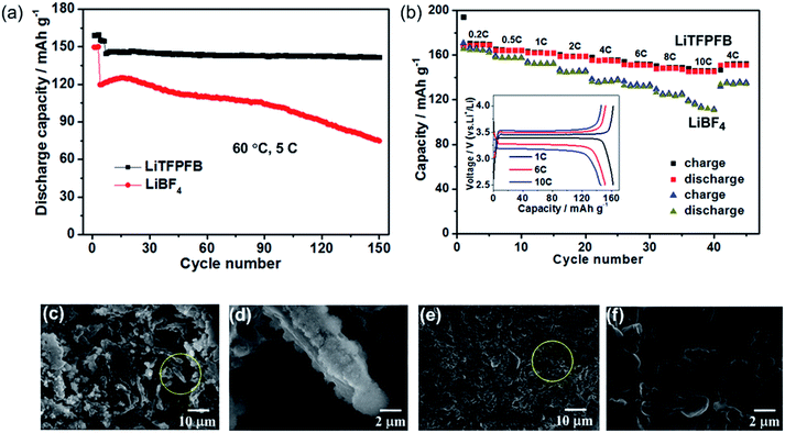
The LiFePO4/Li cells with LiBF4 and LiTFPFB were also cycled at elevated temperature (60 °C), respectively. After three SEI formation cycles at 1C, the cells were cycled at a high current rate of 5C. As depicted in Fig. 5a, the LiTFPFB based battery delivers a superior cycling performance compared to that of the LiBF4 based cell. After 150 cycles, the former retains 98.3% of the fourth cycle discharge capacity, while the capacity retention of the latter is only 62.5%. It is worth noting that the LiFePO4/Li cell also operates well with the LiTFPFB based electrolyte compared with the LiBF4 based one at −5 °C (Fig. S12†). The rate performances of the LiBF4 and LiTFPFB based electrolytes were measured at different rates from 0.2C to 10C at 60 °C. As shown in Fig. 5b, the LiTFPFB based cell shows better rate capability than that of LiBF4 when the rate is varied from 0.2C to 10C. It is indicated that the former delivers a high reversible capacity of 145.8 mA h g−1 at 10C, while the corresponding capacity of the latter is only 116.5 mA h g−1. Furthermore, the selected charge/discharge curves of a LiTFPFB based LiFePO4/Li cell at 1C, 6C and 10C are plotted in the inset of Fig. 5b, demonstrating clear potential plateaus with a small overpotential, which indicates a highly reversible cycling process. The outstanding cycle and rate performance of the LiTFPFB based cells are closely related to the high ionic conductivity and the as-formed protective film on the Li metal anode, which can suppress further decomposition of the electrolyte. To evaluate the morphologies of the Li anodes after long-term cycling, the LiFePO4/Li batteries after 150 cycles were disassembled inside a glovebox with an Ar atmosphere and the obtained electrodes were washed with anhydrous DMC, dried and further analyzed by field emission scanning electron microscopy (FE-SEM). As shown in Fig. 5c–f, the Li surfaces of the LiBF4 and LiTFPFB based cells exhibit entirely different morphologies. It is noted that, for the LiBF4 based LiFePO4/Li cell after 150 cycles at 60 °C, the cycled Li metal exhibits dendritic features with a pulverized and porous morphology (Fig. 5c and d). A large amount of bulk Li was consumed during cycling due to the repeated breakage/repair of the SEI.26 In addition, a pulverized layer is also observed on the newly formed Li dendrite (Fig. 5d). In contrast, the cycled Li metal in the LiTFPFB based cell shows smooth features and absence of Li dendrites (Fig. 5f), although the surface looks rimous (Fig. 5e). These results indicate that the protective film on the Li anode can effectively suppress the parasitic reactions on the surface of the Li anode, thus improving the battery performance.
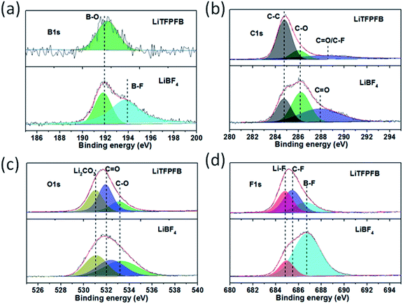
In order to investigate the composition of the protective film, the surface chemistry of the cycled Li anodes was surveyed using X-ray photoelectron spectroscopy (XPS). Fig. 6 shows the XPS spectra of B 1s, C 1s, O 1s, and F 1s for the cycled Li anodes with 1.0 M LiBF4 and 1.0 M LiTFPFB in PC, respectively. As shown in Fig. 6a, the XPS spectrum of B 1s for the LiBF4 based cell can be deconvoluted into two peaks at 192 and 194 eV, which can be assigned to B–O (reaction product of LiBF4 with ROCO2Li) and B–F species.23,27 In contrast, only B–O species can be observed in the LiTFPFB based cell, indicating the decomposition of TFPFB− on the Li anode. Fig. 6b displays the C 1s spectra, and the three peaks centered at 284.8, 286.2, and 287.9 eV correspond to C–C, C–O, and C![[double bond, length as m-dash]](https://www.rsc.org/images/entities/char_e001.gif) O functional groups,27 respectively. The higher concentrations of C–O and C
O functional groups,27 respectively. The higher concentrations of C–O and C![[double bond, length as m-dash]](https://www.rsc.org/images/entities/char_e001.gif) O groups in the LiBF4 based cell can be attributed to PC solvent decomposition, while the higher concentration of C–C combined with lower C–O and C
O groups in the LiBF4 based cell can be attributed to PC solvent decomposition, while the higher concentration of C–C combined with lower C–O and C![[double bond, length as m-dash]](https://www.rsc.org/images/entities/char_e001.gif) O concentrations in the LiTFPFB based cells might be related to TFPFB− decomposition,28 consistent with the O 1s spectra in Fig. 6c. These results indicate the decomposition of the TFPFB− anion and the formation of a protective film on the Li anode, which can inhibit further decomposition of the electrolyte, coinciding with SEM imaging. Furthermore, as for the F 1s spectra (Fig. 6d), the three peaks located at 684.8, 685.6, and 686.8 eV for the LiTFPFB based cell can be assigned to LiF, C–F, and B–F compounds, respectively,23 which originate from the –CF3 (ref. 13) and –BF3 groups in the TFPFB− anion. Similarly, the LiF and B–F species in the LiBF4 based cell originate from the decomposition of LiBF4. In addition, comparing the Li anode after 1 and 100 cycles, the dramatic concentration increase of C species (from 8.9% to 45.0%) and sharp concentration decrease of F species (from 35.1% to 9.0%) may further verify the decomposition of the TFPFB− anion (Fig. S13, Table S2†), in agreement with the mechanism proposed by Abraham et al.12 Based on the above results, it can be concluded that the decomposition of LiTFPFB can form a protective film containing a large number of C–C groups on the Li anode, which can effectively prevent further corrosion of Li metal.
O concentrations in the LiTFPFB based cells might be related to TFPFB− decomposition,28 consistent with the O 1s spectra in Fig. 6c. These results indicate the decomposition of the TFPFB− anion and the formation of a protective film on the Li anode, which can inhibit further decomposition of the electrolyte, coinciding with SEM imaging. Furthermore, as for the F 1s spectra (Fig. 6d), the three peaks located at 684.8, 685.6, and 686.8 eV for the LiTFPFB based cell can be assigned to LiF, C–F, and B–F compounds, respectively,23 which originate from the –CF3 (ref. 13) and –BF3 groups in the TFPFB− anion. Similarly, the LiF and B–F species in the LiBF4 based cell originate from the decomposition of LiBF4. In addition, comparing the Li anode after 1 and 100 cycles, the dramatic concentration increase of C species (from 8.9% to 45.0%) and sharp concentration decrease of F species (from 35.1% to 9.0%) may further verify the decomposition of the TFPFB− anion (Fig. S13, Table S2†), in agreement with the mechanism proposed by Abraham et al.12 Based on the above results, it can be concluded that the decomposition of LiTFPFB can form a protective film containing a large number of C–C groups on the Li anode, which can effectively prevent further corrosion of Li metal.
For practical application in high energy lithium batteries, the LiTFPFB based electrolyte should also be compatible with the LiCoO2 electrode, since it is most commonly used as the standard cathode in state-of-the-art Li ion batteries. To demonstrate the compatibility of LiTFPFB with the LiCoO2 cathode, LiCoO2/Li cells were assembled and evaluated at a current rate of 1C between 2.75 and 4.35 V. Fig. 7 shows the long-term cycling performance of the LiTFPFB and LiBF4 based cells. The initial discharge capacities of the LiTFPFB and LiBF4 based cells are 151.7 and 138 mA h g−1 at 0.2C, with the corresponding coulombic efficiencies of 99.6 and 99.2%, respectively. The former also exhibits a remarkably improved cycling performance compared to the latter at a current rate of 1C (140 mA g−1). The LiTFPFB based cell retains 91.1% of the fourth cycle discharge capacity after 500 cycles with a coulombic efficiency of 99.5%, while the capacity retention of the LiBF4 based cell is 89.2% with a coulombic efficiency of 99.3%. These results indicate that the LiTFPFB based electrolyte is more compatible with the LiCoO2 based cathode than the LiBF4 based one under a high voltage of 4.35 V, making LiTFPFB a promising candidate for practical application in high power and energy density rechargeable lithium batteries.
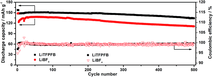 | ||
| Fig. 7 Discharge capacities and coulombic efficiencies of the LiCoO2/Li cells using 1.0 M LiTFPFB/PC and 1.0 M LiBF4/PC at a current rate of 1C at room temperature. | ||
3. Conclusions
In summary, a novel lithium salt, LiTFPFB, has been prepared by a one-step Lewis acid–base reaction. The LiTFPFB salt with a bulky anion exhibits a tLi+ value as high as 0.48, superior oxidation potential, and non-corrosivity to an Al current collector up to 4.5 V. The ionic conductivity of the LiTFPFB/PC electrolyte is three times higher than that of the LiBF4/PC electrolyte over the whole temperature range. Crucially, the fluoroalkoxyl group in LiTFPFB enables the formation of a favorable protective film on the lithium anode, which effectively prevents further corrosion of Li metal with the electrolyte. Together with high ionic conductivity and lithium anode protection properties, LiFePO4/Li cells using LiTFPFB/PC electrolyte show superior cycling stability and rate performance compared to those of LiBF4/PC electrolyte at room temperature and elevated temperature (60 °C). More importantly, LiTFPFB based LiCoO2/Li cells also show improved cycling performance. All of these results suggest that LiTFPFB would be a promising salt for next generation lithium-metal-based batteries with improved safety and electrochemical performance.Conflicts of interest
There are no conflicts to declare.Acknowledgements
This work was financially supported by the National Natural Science Foundation for Distinguished Young Scholars of China (51625204), the National Natural Science Foundation of China (51502319), the Shandong Provincial Natural Science Foundation (ZR2016BQ18), and the Youth Innovation Promotion Association of CAS (2016193).Notes and references
- J. B. Goodenough and K.-S. Park, J. Am. Chem. Soc., 2013, 135, 1167–1176 CrossRef CAS PubMed.
- J. M. Tarascon and M. Armand, Nature, 2001, 414, 359–367 CrossRef CAS PubMed.
- R. Petibon, L. Madec, D. W. Abarbanel and J. R. Dahn, J. Power Sources, 2015, 300, 419–429 CrossRef CAS.
- S. S. Zhang, K. Xu and T. R. Jow, J. Power Sources, 2003, 115, 137–140 CrossRef CAS.
- F. Wu, Q. Zhu, R. Chen, N. Chen, Y. Chen and L. Li, Chem. Sci., 2015, 6, 7274–7283 RSC.
- H. Tsunekawa, A. Narumi, M. Sano, A. Hiwara, M. Fujita and H. Yokoyama, J. Phys. Chem. B, 2003, 107, 10962–10966 CrossRef CAS.
- R. Meziane, J.-P. Bonnet, M. Courty, K. Djellab and M. Armand, Electrochim. Acta, 2011, 57, 14–19 CrossRef CAS.
- Q. Ma, H. Zhang, C. Zhou, L. Zheng, P. Cheng, J. Nie, W. Feng, Y.-S. Hu, H. Li, X. Huang, L. Chen, M. Armand and Z. Zhou, Angew. Chem., Int. Ed., 2016, 55, 2521–2525 CrossRef CAS PubMed.
- M. Ue, T. Fujii, Z. B. Zhou, M. Takeda and S. Kinoshita, Solid State Ionics, 2006, 177, 323–331 CrossRef CAS.
- S. S. Zhang, Electrochem. Commun., 2006, 8, 1423–1428 CrossRef CAS.
- C.-C. Su, M. He, P. C. Redfern, L. A. Curtiss, I. A. Shkrob and Z. Zhang, Energy Environ. Sci., 2017, 10, 900–904 CAS.
- I. A. Shkrob, J. F. Wishart and D. P. Abraham, J. Phys. Chem. C, 2015, 119, 14954–14964 CAS.
- L. Wang, Y. Ma, Y. Qu, X. Cheng, P. Zuo, C. Du, Y. Gao and G. Yin, Electrochim. Acta, 2016, 191, 8–15 CrossRef CAS.
- J. F. Van Humbeck, M. L. Aubrey, A. Alsbaiee, R. Ameloot, G. W. Coates, W. R. Dichtel and J. R. Long, Chem. Sci., 2015, 6, 5499–5505 RSC.
- Z. Zhang, Z. Cui, L. Qiao, J. Guan, H. Xu, X. Wang, P. Hu, H. Du, S. Li and X. Zhou, Adv. Energy Mater., 2017, 1602055 CrossRef.
- M. Ue, A. Murakami and S. Nakamura, J. Electrochem. Soc., 2002, 149, A1572–A1577 CrossRef CAS.
- Z. Cai, Y. Liu, S. Liu, L. Li and Y. Zhang, Energy Environ. Sci., 2012, 5, 5690–5693 CAS.
- K. Xu, Chem. Rev., 2014, 114, 11503–11618 CrossRef CAS PubMed.
- H. Yang, K. Kwon, T. M. Devine and J. W. Evans, J. Electrochem. Soc., 2000, 147, 4399–4407 CrossRef CAS.
- K. Xu, S. S. Zhang, T. R. Jow, W. Xu and C. A. Angell, Electrochem. Solid-State Lett., 2002, 5, A26–A29 CrossRef CAS.
- X. Wang, Z. Liu, C. Zhang, Q. Kong, J. Yao, P. Han, W. Jiang, H. Xu and G. Cui, Electrochim. Acta, 2013, 92, 132–138 CrossRef CAS.
- X.-G. Sun, S. Wan, H. Y. Guang, Y. Fang, K. S. Reeves, M. Chi and S. Dai, J. Mater. Chem. A, 2017, 5, 1233–1241 CAS.
- C. Liao, K. S. Han, L. Baggetto, D. A. Hillesheim, R. Custelcean, E.-S. Lee, B. Guo, Z. Bi, D.-e. Jiang, G. M. Veith, E. W. Hagaman, G. M. Brown, C. Bridges, M. P. Paranthaman, A. Manthiram, S. Dai and X.-G. Sun, Adv. Energy Mater., 2014, 4, 1301368 CrossRef.
- Q. Lu, Y.-B. He, Q. Yu, B. Li, Y. V. Kaneti, Y. Yao, F. Kang and Q.-H. Yang, Adv. Mater., 2017, 29, 1604460 CrossRef PubMed.
- Z. Hu, S. Zhang, S. Dong, W. Li, H. Li, G. Cui and L. Chen, Chem. Mater., 2017, 29, 4682–4689 CrossRef CAS.
- N.-W. Li, Y.-X. Yin, C.-P. Yang and Y.-G. Guo, Adv. Mater., 2016, 28, 1853–1858 CrossRef CAS PubMed.
- M. Xu, L. Zhou, Y. Dong, Y. Chen, J. Demeaux, A. D. MacIntosh, A. Garsuch and B. L. Lucht, Energy Environ. Sci., 2016, 9, 1308–1319 CAS.
- Q.-C. Liu, J.-J. Xu, S. Yuan, Z.-W. Chang, D. Xu, Y.-B. Yin, L. Li, H.-X. Zhong, Y.-S. Jiang, J.-M. Yan and X.-B. Zhang, Adv. Mater., 2015, 27, 6089 CrossRef CAS PubMed.
Footnote |
| † Electronic supplementary information (ESI) available: Experimental method, synthetic procedure, lithium ion transference number, impedance spectra, equivalent circuit diagram and additional XPS data. See DOI: 10.1039/c8sc00041g |
| This journal is © The Royal Society of Chemistry 2018 |


