A flexible dual solid-stateelectrolyte supercapacitor with suppressed self-discharge and enhanced stability†
Haiyan
Wang
,
Jiayi
Chen
,
Ruxue
Fan
and
Yong
Wang
 *
*
Advanced Materials and Catalysis Group, Institute of Catalysis, Zhejiang University, Hangzhou 310028, P. R. China. E-mail: chemwy@zju.edu.cn
First published on 18th September 2018
Abstract
Redox supercapacitors (SCs) have recently been developed as a high-efficiency strategy for energy storage due to their high charge storage capacity and easy accessibility. Developing a low-cost, highly efficient and universal method to control the self-discharge (SDC) process of redox supercapacitors (SCs) would amplify their applications in energy storage. This report on a novel dual solid-state electrolyte supercapacitor (DSES) has demonstrated that the addition of polyvinyl alcohol (PVA) into a CuCl2/H2SO4 active electrolyte could significantly suppress the SDC process, which takes 10 times longer for 50% energy retention, benefiting from moderate kinetics and ion crossover rate. The role of the dual electrolyte system is also illustrated to be effective for improving the cycling stability. Hence, our strategy, which is effective in enhancing the energy storage, mitigating the SDC process and improving the cycling stability, could provide a versatile method for designing low-cost and stable redox SCs for energy storage.
Introduction
Electrochemical double-layer capacitors (EDLCs), known as supercapacitors (SCs), accumulate ions of opposite charge in a double layer on the surface of high-surface-area carbon, and are able to deliver higher power (103 to 105 W kg−1) and longer cycle life than batteries.1–3 Despite that, the charge being confined to the surface results in a medium energy density (4–5 W h kg−1), which is much lower than that of batteries (20 to 150 W h kg−1) and is popularly perceived as the main impediment to the growth of the SC market.4–6 The energy gap between batteries and SCs usually can be minimized via introducing faradaic reactions into the purely capacitive process. Hence, various strategies such as hybridizing with heteroatoms,7–11 organic molecules,12,13 transition metal oxides/hydroxides14–18 or conducting polymers19 have been implemented on porous carbon. Apart from the capacitance improvement, most of them still suffer from decreased conductivity, inferior cycling stability and complicated synthetic routes.The recently developed ‘redox SCs’, with redox-active electrolytes substituting for inert ones, are another promising alternative. The approach involves highly soluble redox couples and less-expensive carbon, and thus is highly efficient and cost-effective compared with solid redox active electrodes. Until now, diverse redox additives including hydroquinone, copper salts, halides, vanadium complexes, methylene blue and ferricyanide20–25 have been reported to significantly augment the capacitance of SCs. Nevertheless, one of the biggest challenges that prevent their wide applications remains the fast self-discharge (SDC) process, which can occur via migration of mobile redox species, diffusion overvoltage losses or intermixing of redox couples.20,21,23,26 Accounting for high SDC rates of little practical use, some strategies such as Nafion cation-exchange membranes,21,24 active copper salts which can convert into insoluble Cu species,21 or an electrostatic adsorption mechanism27 have been proposed to control the SDC process. But some negative effects such as high cost, inferior cycling stability or slender progress still seriously prohibit their wide application. Boettcher et al. have recently achieved great progress by facilitating electrostatic adsorption of charged redox couples on an electrode with methyl viologen/bromide as the electrolyte, thereby significantly slowing down the SDC rate.23 Besides the improvement, its application is still limited by the specific type of electrolytes that could be used and little work has been reported on successful mitigation of the SDC process of redox SCs.
Here, we demonstrate a novel dual solid-state electrolyte supercapacitor (DSES) to increase capacitance and meanwhile mitigate the SDC process, as well as improve the cycling stability. The DSES device with CuCl2/polyvinyl alcohol (PVA)/H2SO4 and PVA/H2SO4 as the electrolytes at the positive and negative electrodes, respectively, is designed for the assembly of porous carbon cloth (CC)-based SCs. CuCl2 in acidic media has been chosen as the active couple because of its fast electron-transfer kinetics during charge/discharge. The combination of double-layer capacitance with pseudocapacitance provided by the redox active electrolytes leads to a tremendous increase in the overall capacitance of the DSES device up to 4148 mF cm−2 at 4 mA cm−2, which is five times higher than that in the absence of CuCl2. Although the intermixing of redox species can be suppressed by conversion to insoluble Cu,21 the SDC rate in the CuCl2/H2SO4 aqueous electrolyte is still rapid. Also, it was found that the fast SDC process complied with the diffusion-control mechanism. In consideration of the slower kinetics and lower ionic crossover between polymer electrolyte/electrode interfaces, PVA polymer was further added into the aqueous system. It was demonstrated to be effective in controlling the SDC effect, which took 10 times longer for 50% energy retention (18![[thin space (1/6-em)]](https://www.rsc.org/images/entities/char_2009.gif) 465 s) than the time taken in the aqueous electrolyte (1720 s). Moreover, the pore blockage of the negative electrode in a single solid-state electrolyte supercapacitor (SSES) caused by insoluble species could be mitigated with dual polymer electrolytes, and a better cycling stability of 92% capacitance retention after 3000 cycles, compared with 35% for SSES, is achieved. This new system might shed light on developing low-cost and stable redox energy storage devices.
465 s) than the time taken in the aqueous electrolyte (1720 s). Moreover, the pore blockage of the negative electrode in a single solid-state electrolyte supercapacitor (SSES) caused by insoluble species could be mitigated with dual polymer electrolytes, and a better cycling stability of 92% capacitance retention after 3000 cycles, compared with 35% for SSES, is achieved. This new system might shed light on developing low-cost and stable redox energy storage devices.
Results and discussion
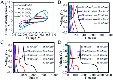
Ultramicroporous carbon cloth (TCC), prepared by a simple high-temperature calcination of commercial carbon cloth, was chosen as the electrode material as it possesses high flexibility, good conductivity and high specific surface area.28 The SEM image of TCC is shown in Fig. S1.† The TCC electrode exhibits a quasi-rectangular shape in its cyclic voltammetry (CV) curve with broad pseudocapacitive peaks at ∼0.3 V in 1 M H2SO4 resulting from additional oxygen functional groups (Fig. S2†).22 As shown in Fig. 1A, the addition of CuCl2 to the H2SO4 supporting electrolyte leads to a significant increase in the area of the CV curve at the same scan rate, indicating a higher capacitance. Here a redox peak at around 0.45 V is observed in 0.1 M CuCl2 acidic solution, which can be attributed to the redox reaction involving Cu2+. A further increase in the concentration of CuCl2 leads to higher currents and broader CVs, demonstrating an enhanced redox pseudocapacitance induced by electroactive Cu2+. The GCD curves in Fig. S3† and 1B–D also demonstrate an increase of capacitance with the increase of CuCl2 concentration. The maximum capacitance for the TCC electrode calculated from galvanostatic charge and discharge (GCD) curves is 22![[thin space (1/6-em)]](https://www.rsc.org/images/entities/char_2009.gif) 430 mF cm−2 in 0.3 M CuCl2/H2SO4 (Fig. 1D), which is about 20 times larger than the capacitance obtained in the absence of CuCl2. The redox reactions were also pH dependent and the peak current decreased or even disappeared in CV curves at higher pH (Fig. S4†), indicating that the significantly increased capacitance is attributed to pseudocapacitance from redox reactions of Cu2+.
430 mF cm−2 in 0.3 M CuCl2/H2SO4 (Fig. 1D), which is about 20 times larger than the capacitance obtained in the absence of CuCl2. The redox reactions were also pH dependent and the peak current decreased or even disappeared in CV curves at higher pH (Fig. S4†), indicating that the significantly increased capacitance is attributed to pseudocapacitance from redox reactions of Cu2+.
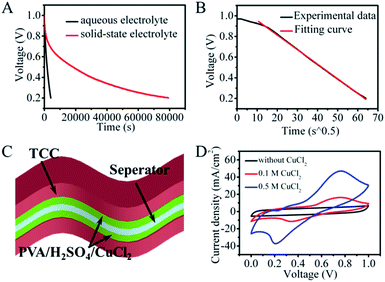
Even though Cu2+ was chosen as the redox species to inhibit the migration of active species, the SDC behavior of the redox aqueous system was also unsatisfactory. As shown in Fig. 2A, the voltage of the CuCl2/H2SO4 aqueous device quickly goes down to 0.5 V within 1720 s and further down to 0.2 V within 4100 s. Fitting of the SDC curve shows a linear relationship between V and t1/2 with a high correlation coefficient R2 (higher than 0.99) (Fig. 2B), demonstrating a diffusion control model.29 At the beginning of the SDC process, a small deviation of the fitting curve was observed, which can be attributed to the more equilibrated state of ions at the electrode/electrolyte interface.30 Thus, we can conclude that the SDC process in the CuCl2/H2SO4 system is probably controlled by ion diffusion/transport.
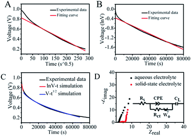
In considering the trade-off between suppression of the SDC behavior and the reaction kinetics, PVA polymer and a higher concentration of Cu2+ were added in the original aqueous solution to further control the shuttling of electrolytes between the two electrodes, as polymer electrolytes usually have moderate kinetics and ion mobility relative to that in aqueous solution. The structure of the SSES device with CuCl2/PVA/H2SO4 as the redox electrolyte is displayed in Fig. 2C. CV and GCD tests were then performed to evaluate the electrochemical performance of the device (Fig. 2D and S5†). Prominent redox waves centered at 0.75 V are exhibited in the CV curves, and their intensities increase with the addition of CuCl2, corresponding to the enhanced capacitance from GCD results. To study the ability of energy retention, a potential decay effect was then monitored at open circuit. As depicted in Fig. 2A, compared with the original system, the SSES with PVA displays a much slower SDC rate. The voltage declining to half of its original value needs 18![[thin space (1/6-em)]](https://www.rsc.org/images/entities/char_2009.gif) 465 s, which is 10 times longer than that of CuCl2/H2SO4 aqueous solution. To explore the SDC mechanism in the device, the SDC curve was analyzed with the well-accepted potential driving model and the diffusion control model.31 However, fitting of the corresponding SDC curve shows that the behavior does not comply with either single control model (Fig. 3A and B), but the SDC process can be controlled with the dual-mechanism model by separating the SDC process into two parts, as depicted in Fig. 3C. The beginning of the SDC process obeys the potential driving model and 50% voltage drop is governed by the diffusion controlled SDC process. The effects of gel electrolytes, electrolyte/electrode interface and the ionic transportation were then reflected on Nyquist plots (Fig. 3D and Table S1†) based on the electrochemical impedance spectroscopy (EIS) test. The Nyquist plots display both a semi-circle in the high-frequency region and a straight line in the low-frequency region, corresponding to an electron-transfer-limited process and a diffusion-limited process, respectively. The higher intersection on the real axis of the Nyquist plot for SSES (3.32 vs. 2.11 Ω, Table S1†), known as series resistance Rs, represents an increased internal resistance associated with the electrolyte resistance, the intrinsic resistance of electrode materials, and the contact resistance at the interface of the electrode. Meanwhile, the larger semi-circle in the high frequency region (charge transfer resistance, Rct, Table S1†) for SSES, involving the process occurring at the electrode/electrolyte interface, suggests relatively poor ionic conductivity at the electrode–electrolyte interface with the addition of the polymer electrolyte. These variations all relate to the slightly slow kinetics in polymer electrolytes, compared with aqueous electrolytes. In addition, the Warburg region (Wo) between the semicircle and the long tail correlates with the ion diffusion/transport to electrolyte/electrode interfaces and the relatively high Warburg resistance in SSES (2.51 Ω vs. 0.56 Ω) indicates a slower ion diffusion to the electrode surface. Therefore, we can conclude that the slow kinetics and low ion transport rate between the electrolyte and electrode/electrolyte interface can be the main factors for the supression of the SDC process in SSES.
465 s, which is 10 times longer than that of CuCl2/H2SO4 aqueous solution. To explore the SDC mechanism in the device, the SDC curve was analyzed with the well-accepted potential driving model and the diffusion control model.31 However, fitting of the corresponding SDC curve shows that the behavior does not comply with either single control model (Fig. 3A and B), but the SDC process can be controlled with the dual-mechanism model by separating the SDC process into two parts, as depicted in Fig. 3C. The beginning of the SDC process obeys the potential driving model and 50% voltage drop is governed by the diffusion controlled SDC process. The effects of gel electrolytes, electrolyte/electrode interface and the ionic transportation were then reflected on Nyquist plots (Fig. 3D and Table S1†) based on the electrochemical impedance spectroscopy (EIS) test. The Nyquist plots display both a semi-circle in the high-frequency region and a straight line in the low-frequency region, corresponding to an electron-transfer-limited process and a diffusion-limited process, respectively. The higher intersection on the real axis of the Nyquist plot for SSES (3.32 vs. 2.11 Ω, Table S1†), known as series resistance Rs, represents an increased internal resistance associated with the electrolyte resistance, the intrinsic resistance of electrode materials, and the contact resistance at the interface of the electrode. Meanwhile, the larger semi-circle in the high frequency region (charge transfer resistance, Rct, Table S1†) for SSES, involving the process occurring at the electrode/electrolyte interface, suggests relatively poor ionic conductivity at the electrode–electrolyte interface with the addition of the polymer electrolyte. These variations all relate to the slightly slow kinetics in polymer electrolytes, compared with aqueous electrolytes. In addition, the Warburg region (Wo) between the semicircle and the long tail correlates with the ion diffusion/transport to electrolyte/electrode interfaces and the relatively high Warburg resistance in SSES (2.51 Ω vs. 0.56 Ω) indicates a slower ion diffusion to the electrode surface. Therefore, we can conclude that the slow kinetics and low ion transport rate between the electrolyte and electrode/electrolyte interface can be the main factors for the supression of the SDC process in SSES.
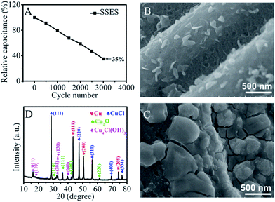
Cycling stability has been considered as another major issue for redox SCs. Fig. 4A shows the cycling performance of the SSES and a big deterioration of the electrochemical performance is observed. As Cu2+ ions can be reduced to insoluble metallic and/or oxidized copper deposited on the negative electrode, the loss of energy can be attributed to the reduced redox-active ions in electrolytes in SSES or the pore blockage effect on porous carbon. To explore the main reason for the reduced charge storage capacity, a two-electrode liquid electrolyte system was further chosen as redox electrolytes could be easily updated in this system during the cycling test. As shown in Fig. S6,† the area of the CV diminishes significantly after 400 cycles and it cannot be restored even when the two electrodes are then transferred to a new 0.2 M CuCl2/H2SO4 electrolyte solution which is similar to the original, indicating that the lowered concentration of the redox-active species cannot be the main reason for the decline of capacitance. Further clear analysis of the positive and negative electrodes with scanning electron microscopy (SEM) images (Fig. 4B and C and S7†) and the comparison with that of TCC before the cycling test (Fig. S1†) reveal that a layer of deposit covers the surface of the negative electrode and plugs the pores of TCC, but the positive electrode surface shows no significant change. The reason can be ascribed to the occurrence of the reduction process of Cu2+ on the surface of the negative electrode during the cathodic polarization. The X-ray diffraction (XRD) pattern of the surface layer on the negative electrode after the CV cycling performance is shown in Fig. 4D. It exhibits three distinct peaks at 43.4°, 50.5° and 74.3°, corresponding to the (111), (200) and (208) planes of Cu, respectively. The peaks at 28.5°, 47.5°, 56.3°, 69.7°, and 76.6° which are characteristic of CuCl and Cu4Cl(OH)3 also exist. As a result of the chemical instability of Cu+, a small amount of Cu2O is present. The associated reaction processes are described in the ESI.† Hence, we can conclude that the poor cycling performance of SSES is primarily caused by the deposition of metallic and nonmetallic copper precipitates on the surface of the negative electrode. The ultramicropores of TCC were blocked by a thick layer of deposits and therefore, this result in a lower ion accessible surface area and poor reaction kinetics, as well as decreased electrical double-layer capacitance and redox capacitance. Also, the surface layer of the deposits contains a complex mix of metallic and oxidized copper, which increases the contact resistance of the electrode and meanwhile impedes the charge storage performance.32
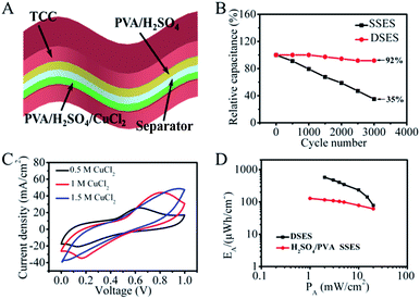
To improve the cycling performance and remit the pore blockage effect, a new DSES was designed with two kinds of solid-state electrolytes. In the DSES device, as displayed in Fig. 5A, the electrolyte in the negative electrode was replaced with PVA/H2SO4, while PVA/H2SO4/CuCl2 was retained as the active electrolyte in the positive electrode. Based on the structure of DSES, the working mechanism is similar to that of an asymmetric SC, where the positive and negative electrodes provide pseudocapacitive and double-layer capacitive behaviors, respectively. As shown in Fig. 5B, excellent cycling performance with 92% capacitance retention after 3000 continuous cycles was achieved with DSES, which is significantly better than the 35% retention for SSES. This is due to the suppression of pore blockage at the surface of the negative electrode with double solid-state electrolytes. Also, Nyquist plots display similar trends after 1000 cycles, suggesting the good electrochemical stability of DSES during the cycling (Fig. S8†). The electrochemical data were collected when the device was at equilibrium. In addition to the improved cycling performance, similar to SSES, DSES shows enhanced capacitive behavior. Fig. 5C shows the CV curves for DSES at different concentrations of the CuCl2/PVA/H2SO4 electrolyte and prominent redox peaks of Cu2+ ions can be observed. A maximum capacitance of 4148 mF cm−2 at a current of 4 mA cm−2 is achieved and also maintains 1680 mF cm−2 at a fast charge/discharge rate of 20 mA cm−2 (Fig. S9†). The corresponding volumetric capacitances are shown in Fig. S10,† and the maximum volumetric capacitance is calculated to be about 46 F cm−3. A Ragone plot is obtained based on the GCD tests and the energy density reaches 576 μW h cm−2, which is 5 times larger than that of SSES with PVA/H2SO4 as the electrolyte (Fig. 5D and S11†). Additionally, the maximum power density reaches 20 mW cm−2, which is slightly lower than that of the aqueous device with 0.3 M CuCl2/1 M H2SO4 as the electrolyte (Fig. S12†). The reason can be ascribed to the relatively slow ion diffusion and the depressed electrochemical kinetics with the addition of PVA.33,34 Also, the DSES device shows a slow SDC rate, as shown in Fig. S13.† Moreover, in order to evaluate the potential of DSES for flexible energy storage, the mechanical flexibility performance was analyzed. The digital photo of DSES in the inset figure shows excellent flexibility. The corresponding CV curves also remain stable under different bending angles (Fig. S14†). These results all prove the effectiveness of this new system in high-performance and stable flexible redox SCs.
Conclusions
In summary, we have demonstrated a novel DSES device, with CuCl2/PVA/H2SO4 and PVA/H2SO4 as the electrolytes at positive and negative electrodes, respectively, to enhance the capacitance and mitigate the SDC process, as well as improve the cycling stability. The device could deliver high capacitance up to 4148 mF cm−2 benefiting from the redox reaction of Cu2+ ions. The SDC process of the redox SC was effectively suppressed with the addition of PVA in the redox electrolyte as a result of moderate kinetics and ion crossover rate relative to the original electrolyte. In addition, the DSES device was demonstrated to be an effective strategy to improve the cycling stability of SSES by remitting pore blockage behavior on the negative electrode. These results might promise the application of our universal strategy in low-cost and stable redox energy storage devices.Experimental
Synthesis of ultramicroporous carbon cloth (TCC)
TCC was synthesized according to the previous report.28 Briefly, commercial CC (Shanghai Hesen Electric Co. Ltd, China, HCCP330) was calcined at 1000 °C for 1 h with a heating rate of 5 °C min. The product was directly used as the electrode material without the need for any other current collector and conductive additive.Morphology and electrochemical characterizations
SEM images were obtained with a SU-70 microscope. X-ray diffraction (XRD) data were collected with a D/tex-Ultima TV wide angle X-ray diffractometer equipped with Cu Kα radiation (λ = 1.54 Å). The cyclic voltammetry (CV) tests, galvanostatic charge/discharge (GCD) data, SDC processes and electrochemical impedance spectroscopy (EIS) measurements were recorded on a Gamry Reference 600 electrochemical workstation and a LAND CT2001A. All the electrochemical tests were conducted at room temperature.Electrochemical tests in aqueous redox electrolytes
A three-electrode electrochemical device was first used to test the electrochemical properties of TCC in CuCl2/H2SO4 redox electrolytes, consisting of a working electrode, and a platinum sheet and an SCE electrode as the counter and reference electrodes, respectively. The two-electrode cell in the aqueous redox electrolyte consisted of two working electrodes separated by filter paper and packaged in CuCl2/H2SO4 electrolytes. The electrochemical data were recorded with the device at equilibrium.Fabrication of a flexible single solid-state electrolyte supercapacitor (SSES)
A flexible SSES was assembled in a symmetrical two-electrode configuration with the addition of PVA into the H2SO4/CuCl2 electrolyte. Specifically, 2 g H2SO4 and corresponding amount of CuCl2 were added into 20 mL water solution. Then, 2 g polyvinyl alcohol (PVA) powder (Aldrich) was added into the above solution and stirred at 85 °C until the PVA dissolved completely. After that, two TCC electrodes and a fiber filter paper were immersed into the electrolyte for 1 h and assembled face to face with a working area of 1 cm2. The assembled device was finally placed under ambient conditions to allow the electrolyte to solidify. The thickness of the SSES is measured to be about 0.9 mm.Fabrication of a flexible dual solid-state electrolyte supercapacitor (DSES)
To suppress the deposition of Cu on the negative electrode which leads to plugging of the pores of carbon and inferior cycling stability, a DSES was designed and assembled. The PVA/H2SO4/CuCl2 gel electrolyte used for the positive electrode was prepared in the same way as that of SSES, while the PVA/H2SO4 gel electrolyte was used for the negative electrode. Finally, a flexible DSES was assembled with a working area of 1 cm2 in the same way as SSES and the thickness of the device was about 0.9 mm. As suggested by Gogotsi and Simon et al., compared with the gravimetric performance, the electrochemical performance based on the total area/volume of the assembled device is more reliable,4,35–38 our study mainly provides the areal and volumetric performance of the whole device.Conflicts of interest
There are no conflicts to declare.Acknowledgements
Financial support from the National Key R&D Program of China (2016YFA0202900), the Key Program Supported by the Natural Science Foundation of Zhejiang Province, China (LZ18B060002), the National Natural Science Foundation of China (21622308, 91534114) and the Fundamental Research Funds for the Central Universities (2017XZZX002-16) is greatly appreciated.Notes and references
- Z. Wu and X. B. Zhang, Acta Phys.-Chim.Sin., 2017, 33, 305–313 CAS.
- P. Simon and Y. Gogotsi, Nat. Mater., 2008, 7, 845 CrossRef CAS PubMed.
- L. Xie, H. Y. Wang, C. H. Chen, S. J. Mao, Y. Q. Chen, H. R. Li and Y. Wang, Research, 2018 DOI:10.1155/2018/5807980.
- P. Simon and Y. Gogotsi, Acc. Chem. Res., 2013, 46, 1094–1103 CrossRef CAS PubMed.
- P. S. J. R. Miller, science, 2008, 321, 651–652 CrossRef PubMed.
- M. F. El-Kady, V. Strong, S. Dubin and R. B. Kaner, Science, 2012, 335, 1326–1330 CrossRef CAS PubMed.
- T. Lin, I.-W. Chen, F. Liu, C. Yang, H. Bi, F. Xu and F. Huang, Science, 2015, 350, 1508–1513 CrossRef CAS PubMed.
- Y. Zhou, X. Xu, B. Shan, Y. Wen, T. Jiang, J. Lu, S. Zhang, D. P. Wilkinson, J. Zhang and Y. Huang, Energy Storage Materials, 2015, 1, 103–111 CrossRef.
- Z. Wu and X. B. Zhang, Sci. China Mater., 2016, 59, 547–557 CrossRef CAS.
- J. Zhao, H. W. Lai, Z. Y. Lyu, Y. F. Jiang, K. Xie, X. Z. Wang, Q. Wu, L. J. Yang, Z. Jin, Y. W. Ma, J. Liu and Z. Hu, Adv. Mater., 2015, 27, 3541–3545 CrossRef CAS PubMed.
- G. Zhu, T. Chen, Y. Hu, L. Ma, R. Chen, H. Lv, Y. Wang, J. Liang, X. Li, C. Yan, H. Zhu, H. Liu, Z. Tie, Z. Jin and J. Liu, Nano Energy, 2017, 33, 229–237 CrossRef CAS.
- S. Gan, L. Zhong, L. Gao, D. Han and L. Niu, J. Am. Chem. Soc., 2016, 138, 1490–1493 CrossRef CAS PubMed.
- M. Boota, C. Chen, M. Becuwe, L. Miao and Y. Gogotsi, Energy Environ. Sci., 2016, 9, 2586–2594 RSC.
- H. Wang, R. Fan, J. Miao, J. Chen, S. Mao, J. Deng and Y. Wang, J. Mater. Chem. A, 2018, 6, 6780–6784 RSC.
- H. Wang, C. Xu, Y. Chen and Y. Wang, Energy Storage Materials, 2017, 8, 127–133 CrossRef.
- X. H. Cao, B. Zheng, W. H. Shi, J. Yang, Z. X. Fan, Z. M. Luo, X. H. Rui, B. Chen, Q. Y. Yan and H. Zhang, Adv. Mater., 2015, 27, 4695–4701 CrossRef CAS PubMed.
- J. Zhou, Y. Huang, X. Cao, B. Ouyang, W. Sun, C. Tan, Y. Zhang, Q. Ma, S. Liang, Q. Yan and H. Zhang, Nanoscale, 2015, 7, 7035–7039 RSC.
- J. Chen, H. Wang, J. Deng, C. Xu and Y. Wang, J. Mater. Chem. A, 2018, 6, 8986–8991 RSC.
- Q. Meng, K. Cai, Y. Chen and L. Chen, Nano Energy, 2017, 36, 268–285 CrossRef CAS.
- R. Silvia, B. Clara, G. Marcos, M. Rosa and S. Ricardo, Angew. Chem., Int. Ed., 2011, 123, 1737–1739 CrossRef.
- L. B. Chen, H. Bai, Z. F. Huang and L. Li, Energy Environ. Sci., 2014, 7, 1750–1759 RSC.
- L.-Q. Mai, A. Minhas-Khan, X. Tian, K. M. Hercule, Y.-L. Zhao, X. Lin and X. Xu, Nat. Commun., 2013, 4, 2923 CrossRef PubMed.
- S. E. Chun, B. Evanko, X. F. Wang, D. Vonlanthen, X. L. Ji, G. D. Stucky and S. W. Boettcher, Nat. Commun., 2015, 6, 7818 CrossRef CAS PubMed.
- F. Elzbieta, F. Krzysztof, M. Mikolaj and L. Grzegorz, ChemSusChem, 2012, 5, 1181–1185 CrossRef PubMed.
- C. Xu, H. Wang, J. Deng and Y. Wang, Sustainable Energy Fuels, 2018, 2, 357–360 RSC.
- S. T. Senthilkumar, R. K. Selvan and J. S. Melo, J. Mater.Chem. A, 2013, 1, 12386–12394 RSC.
- B. Wang, J. A. Macia-Agullo, D. G. Prendiville, X. Zheng, D. Liu, Y. Zhang, S. W. Boettcher, X. Ji and G. D. Stucky, J. Electrochem. Soc., 2014, 161, A1090–A1093 CrossRef CAS.
- H. Wang, J. Deng, C. Xu, Y. Chen, F. Xu, J. Wang and Y. Wang, Energy Storage Materials, 2017, 7, 216–221 CrossRef.
- B. W. Ricketts and C. Ton-That, J. Power Sources, 2000, 89, 64–69 CrossRef CAS.
- Q. Zhang, J. Rong, D. Ma and B. Wei, Energy Environ. Sci., 2011, 4, 2152–2159 RSC.
- Q. Zhang, C. Cai, J. Qin and B. Wei, Nano Energy, 2014, 4, 14–22 CrossRef CAS.
- J.-J. Velasco-Vélez, K. Skorupska, E. Frei, Y.-C. Huang, C.-L. Dong, B.-J. Su, C.-J. Hsu, H.-Y. Chou, J.-M. Chen, P. Strasser, R. Schlögl, A. Knop-Gericke and C.-H. Chuang, J. Phys. Chem. B, 2018, 122, 780–787 CrossRef PubMed.
- Y. Huang, M. Zhong, Y. Huang, M. Zhu, Z. Pei, Z. Wang, Q. Xue, X. Xie and C. Zhi, Nat. Commun., 2015, 6, 10310 CrossRef CAS PubMed.
- Y. Huang, M. Zhong, F. Shi, X. Liu, Z. Tang, Y. Wang, Y. Huang, H. Hou, X. Xie and C. Zhi, Angew. Chem., Int. Ed., 2017, 56, 9141–9145 CrossRef CAS PubMed.
- Y. Gogotsi and P. Simon, Science, 2011, 334, 917–918 CrossRef CAS PubMed.
- P. Simon and Y. Gogotsi, Nat. Mater., 2008, 7, 845–854 CrossRef CAS PubMed.
- X. Lu, M. Yu, G. Wang, Y. Tong and Y. Li, Energy Environ. Sci., 2014, 7, 2160–2181 RSC.
- Y. Z. Zhang, Y. Wang, T. Cheng, W. Y. Lai, H. Pang and W. Huang, Chem. Soc. Rev., 2015, 44, 5181–5199 RSC.
Footnote |
| † Electronic supplementary information (ESI) available: Calculations, characterizations, electrochemical data and references. See DOI: 10.1039/c8se00364e |
| This journal is © The Royal Society of Chemistry 2018 |

