A cobalt hydroxide-based compressible electrode material for asymmetrical all-solid supercapacitors†
Yuanyuan
Yang
ab,
Yuan
Tu
a,
Pengli
Zhu
 *a,
Leicong
Zhang
a,
Tingxi
Li
*b,
Hairong
Zheng
c,
Rong
Sun
 *a and
Chingping
Wong
de
aGuangdong Provincial Key Laboratory of Materials for High Density Electronic Packaging, Shenzhen Institutes of Advanced Technology, Chinese Academy of Sciences, Shenzhen 518055, P. R. China. E-mail: pl.zhu@siat.ac.cn
bSchool of Materials Science and Engineering, Shandong University of Science and Technology, Qingdao 266590, P. R. China. E-mail: litx@sdust.edu.cn
cShenzhen Institutes of Advanced Technology, Chinese Academy of Sciences, Shenzhen 518055, P. R. China
dSchool of Materials Science and Engineering, Georgia Institute of Technology, Atlanta, USA
eDepartment of Electronics Engineering, The Chinese University of Hong Kong, Hong Kong
First published on 23rd August 2018
Abstract
A compressible supercapacitor is a promising energy storage device for wearable flexible electronic devices. In this study, a compressible electrode material of MF/Ni(II)–Co(OH)2 based on melamine foam (MF) for all-solid supercapacitors was fabricated by an electroless plating and electrodeposition method. The electrode of MF/Ni(I) was prepared by electroless plating on commercial MF, and the subsequent step of electrodeposition was introduced to fabricate MF/Ni(II) and MF/Ni(II)–Co(OH)2. The electrochemical results show that the obtained compressible electrode material exhibits exceptional capacitive behavior (volumetric capacitance of 8.82 F cm−3 at 3 mA cm−3), cycling stability (80.95% capacitance retention after 1000 cycles at 10 mA cm−3), and superior compression stability (93.81% capacitance retention even under 50% compression). Then, a compressible asymmetrical all-solid supercapacitor was fabricated with MF/Ni(II)–Co(OH)2 as the positive electrode and Ni/carbon (Ni/C) as the negative electrode, separated by laboratory filter paper and KOH–poly(vinyl alcohol) (PVA) electrolyte. Such a compressible supercapacitor displays good capacitive behavior, exceptional compression stability (84.21% capacitance retention even under 50% compression) and cycling stability (94.44% capacitance retention after 1000 cycles at 10 mA cm−3). It has been shown that the assembled compressible supercapacitor can be used as a power source to drive a light-emitting diode (LED) and it can work properly under different compression conditions. These favorable results demonstrate that MF/Ni(II)–Co(OH)2 is an appropriate electrode material for compressible supercapacitors.
1. Introduction
Supercapacitors, also known as electrochemical capacitors, store energy relying on either ion adsorption (electrochemical double layer capacitors (EDLCs)) on the electrode surface or fast surface reversible faradaic redox reactions (pseudo-capacitors).1 Supercapacitors are considered as promising energy storage devices due to their high energy density,2 long cycle life,3 fast charge/discharge rate4 and simple preparation method,5 and have been widely used in mobile electronics, laptops, digital cameras, emergency doors, and hybrid electric vehicles as well as other commercial electronic products, affecting people's daily life all the time.6,7 With the rapid development of electronic devices, more and higher requirements have been put forward for supercapacitors, such as more miniaturization,8 flexibility,9 portability,10 compressibility,11,12etc. Conventional supercapacitors with bulk and rigid electrodes have been unable to meet the development needs of electronic devices. Therefore, it is urgent to research wearable flexible supercapacitors which can be bent, folded, and compressed while maintaining their electrochemical functions for the rapid development of electronic devices.13–15Among various flexible wearable supercapacitors, the compressible supercapacitor has attracted a great deal of attention because it can retain its initial capacitance under and after recovery from different compression conditions.16 Therefore, the selection of material and design of compressible supercapacitors are especially important; different types of compressible supercapacitors have been designed and prepared by researchers,17–20 and they can be divided into the following three types according to their compression skeleton: (1) carbon nanotube (CNT) foam-based compressible supercapacitors. CNT foam has attracted wide attention as a compressible electrode material due to its high electrical conductivity,21 excellent mechanical properties and light weight.17 Therefore, CNT foam can be a self-supporting electrode material with excellent performance for compressible supercapacitors.22,23 However, the low specific capacitance derived from the low specific surface area and energy storage mechanism of EDLCs still limits the application of pure CNTs in compressible supercapacitors. In order to increase the specific capacitance, pseudocapacitance materials such as conductive polymers (polypyrrole (PPy)24,25 and poly(3,4-ethylenedioxythiophene) (PEDOT)26), transition metal oxides (manganese oxide (MnO2)27–29 and α-Fe2O3 (ref. 30)), and Ni–Co metal oxides (NiCo2O4)31 were introduced into CNT foam to prepare a composite compressible electrode material. (2) Graphene aerogel (GA) based compressible supercapacitors. GA with monolithic blocks or continuous fibers is an excellent electrode material for compressible supercapacitors owing to its light weight, high porosity and flexibility.32 Nevertheless, pure GA structures tend to collapse when subjected to forces due to their poor elasticity and compressibility, and the specific capacitance of GA is too low for practical application; hence, an effective method is to combine the graphene aerogel with pseudocapacitive materials like PPy,33,34 polyaniline (PANI)35 and ternary composites36 to form composite aerogel electrodes for improving their specific capacitance while maintaining their compressibility. (3) MF-based compressible supercapacitors. MF is an inexpensive elastic material for compressible supercapacitors due to its three-dimensional network structure and high specific surface area. MF can be used as a compressible skeleton for preparing compressible electrode materials.37 After high-temperature carbonization, MF can maintain its compressibility and improve its conductivity. Therefore, carbonized MF can be directly used as an electrode material for compressible supercapacitor.38
Cobalt hydroxide (Co(OH)2), as a layered 2D transition metal hydroxide, has attracted much interest as a supercapacitor electrode material due to its special electronic properties,39 interlayer chemistry,40 and high theoretical specific capacitance.41 There has been a lot of work on sheet-like cobalt hydroxide electrode materials towards supercapacitor applications.42–45 However, the low conductivity of cobalt hydroxide limits its practical application and rapid development as a supercapacitor electrode material. Therefore, in order to improve the conductivity of the cobalt hydroxide electrode material, some strategies were adopted by researchers, which involve preparation of a composite material of cobalt oxide and cobalt hydroxide.46
MF with a 3D porous structure has become a common substance in our daily lives (such as in furniture, cleaning tools, clothes, packaging, etc.) due to its good thermal insulation performance, elasticity, flame retardancy, sound absorption and noise reduction, safety and health, mechanical processing and other properties. Because of its excellent 3D interconnected porous structure, MF has been used as a substrate for the preparation of electrode materials for compressible supercapacitors.47–50 In this study, we report a compressible electrode material of MF/Ni(II)–Co(OH)2 for all-solid asymmetrical supercapacitors. The MF/Ni(II)–Co(OH)2 was fabricated by an electroless plating and electrochemical deposition strategy to coat a Ni layer on the 3D interconnected porous skeleton of MF and a subsequent electrochemical deposition process to prepare the electrochemically active material of Co(OH)2 on the surface of MF/Ni(II). This work combines the high compressibility of MF with the excellent electrochemical performance of cobalt hydroxide. Moreover, an all-solid asymmetrical compressible supercapacitor was fabricated with MF/Ni(II)–Co(OH)2 as a positive electrode and Ni/carbon (Ni/C) as a negative electrode, separated by laboratory filter paper and KOH–PVA electrolyte.
2. Results and discussion
2.1. Fabrication and characterization
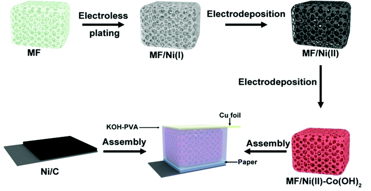
A schematic illustration for the preparation of the MF/Ni(II)–Co(OH)2 compressible electrode material is presents in Fig. 1. The MF is designed to act as the deposition substrate and compressible skeleton. The fabrication procedure of MF/Ni(II)–Co(OH)2 mainly includes the following three steps: (1) the conductive MF/Ni(I) was prepared by electroless nickel plating, and after this step, the first metallic Ni layer was homogeneously plated on the surface of bare MF, forming the basic conductive network. (2) MF/Ni(II) was fabricated through electrodeposition to further improve the electrical conductivity of MF/Ni(I). The good electrical conductivity of MF/Ni(II) is very beneficial to the electrochemical performance of the compressible electrode material. Metallic nickel is used as an excellent conductive material for the deposition of electrochemically active substances in conductors during the preparation of electrode materials. Besides, Ni acts as a current collector in the prepared compressible supercapacitor electrode material. (3) The Co(OH)2 nanosheets used as an electrochemically active material were subsequently covered on the surface of MF/Ni(II) via the constant potential deposition method to prepare the MF/Ni(II)–Co(OH)2 compressible electrode material. Furthermore, we assembled a simple compressible supercapacitor with MF/Ni(II)–Co(OH)2 as a positive electrode and Ni/carbon (Ni/C) as a negative electrode, separated by laboratory filter paper and KOH–PVA electrolyte, and copper foil was used as a wire to connect the electrode material in the device with the test instrument.The I–t curve for the fabrication of MF/Ni(II) via the constant potential deposition method is presented in Fig. S1a.† As depicted in the picture, the current is increased from 155.36 mA to 207.56 mA with the increase of electrodeposition time. This illustrates that the conductivity of MF/Ni(II) is improved since the metallic Ni was attached on the surface of MF/Ni(I), yielding the sample of MF/Ni(II). The resistance of the sample is changed from 10 Ω to 0.7 Ω (measured using a multimeter) after electrochemical nickel plating; this result is consistent with the I–t curve for the fabrication of MF/Ni(II).
Fig. S1b† displays the I–t curve for the fabrication of MF/Ni(II)–Co(OH)2via the constant potential deposition method. As described in the image, the current increases with the electrodeposition time from 0 to 106 s, and the current decreases with the increase of the electrodeposition time from 107 to 900 s. The chemical reaction principle for preparing cobalt hydroxide by this constant potential deposition method can be expressed as53
| NO3− + 7H2O + 8e− → NH4+ + 10OH− | (1) |
| Co2+ + 2OH− → Co(OH)2 | (2) |
This procedure could be explained as follows: at the beginning of the reaction, the current in the entire reaction device increases obviously with the electrodeposition time since the concentration of ions in the solution increases significantly. Then, the electrochemically active material of Co(OH)2 is gradually generated as the reaction proceeds, and the concentration of ions in the solution will gradually decrease, and therefore, there is a phenomenon that the current of the entire reaction device decreases with the increase of the electrodeposition time after 107 s as shown in Fig. S1b.†
In order to evaluate the compressibility of the MF/Ni(II)–Co(OH)2 electrode material, we took photos of MF/Ni(II)–Co(OH)2 under different conditions. The digital photographs (Fig. 2) demonstrate that the MF/Ni(II)–Co(OH)2 electrode material can completely recover to its original size and shape after removing the weight, and the process of compression and recovery can be directly observed through video ESI-1.†
Fig. 3a, c, e and g present the morphology of MF, MF/Ni(I), MF/Ni(II) and MF/Ni(II)–Co(OH)2, respectively, and Fig. 3b, d, f and h display their high-magnification images. As depicted in Fig. 3a, MF is a three-dimensional (3D) interconnected network structure composed of numerous branched fibres with a diameter of several micrometers and smooth surfaces (as shown in Fig. 3b). Taking advantage of the unique 3D interconnected network architecture of MF, an elastic, lightweight, freestanding conductive MF/Ni(I) was prepared by depositing a layer of metallic nickel on the surface of MF via an electroless nickel plating method. As described in Fig. 3c, compared with the original MF, the 3D interconnected network structure was maintained very well. Upon chemical deposition, Ni metal particles with a diameter of several nanometers were formed on the surface of MF fibres and the surface became rougher (Fig. 3d). After that, MF/Ni(II) was prepared via electrochemical deposition to further improve the conductivity of MF/Ni(I). The SEM image of the MF/Ni(II) is shown in Fig. 3e and f; the 3D interconnected network architecture was perfectly maintained, and another dense metallic Ni layer was coated on the surface of MF/Ni(I) (as shown in Fig. 3f) after electrochemical deposition. The morphology of the MF/Ni(II)–Co(OH)2 compressible electrode material is presented in Fig. 3g and h. Similarly, the 3D interconnected framework architecture formed from numerous branched fibres was maintained very well (Fig. 3g). Furthermore, it can be clearly seen from Fig. 3g that the surface roughness of the sample is increased, and the diameter of the branched fibre is increased compared with the two previous samples. In the high-magnification SEM image of MF/Ni(II)–Co(OH)2 (Fig. 3h), it can be seen that the sheet-like material is uniformly aligned vertically and stacked closely on the surface of the branched fibre, which is possibly the Co(OH)2 electrochemically active material. There is a large open framework formed between the intersections of the sheet-like material, which would come more fully into contact with the electrolyte and promote the electrochemical reactions.54
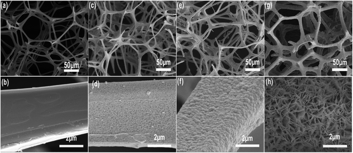 | ||
| Fig. 3 The SEM image of (a and b) MF, (c and d) MF/Ni(I), (e and f) MF/Ni(II) and (g and h) MF/Ni(II)–Co(OH)2 at different magnifications. | ||
In order to further study the structure of the MF/Ni(II)–Co(OH)2 electrode material, the surface of MF/Ni(II)–Co(OH)2 was subjected to Focused Ion Beam (FIB) treatment, and then the surface morphology of MF/Ni(II)–Co(OH)2 was observed by polarizing microscopy and field emission scanning electron microscopy. Fig. S2a and b† display the digital photos of the MF/Ni(II)–Co(OH)2 electrode material taken with a polarizing microscope. The inside and edges of the fibre of the MF/Ni(II)–Co(OH)2 electrode material can be observed after FIB treatment (as shown in Fig. S2b†). Fig. S2c and d† present the SEM images of the MF/Ni(II)–Co(OH)2 electrode material after FIB treatment; the fibre of MF/Ni(II)–Co(OH)2 is composed of three layers. It can be seen that a layer of Co(OH)2 is deposited on the edge of the fibre of MF. Besides, the EDX and elemental area mapping of MF/Ni(II)–Co(OH)2 treated with FIB from the FESEM image was performed to confirm the elemental composition of the prepared electrode material. Fig. S3† presents the EDX spectrum of MF/Ni(II)–Co(OH)2, demonstrating the presence of various elements C, N, Co and Ni in the electrode material. Fig. S4b–e† display the elemental mapping corresponding to the region of Fig. S4a,† which further indicates the distribution of elements C, N, Co and Ni in the MF/Ni(II)–Co(OH)2.
A more detailed morphological characterization of the Co(OH)2 electrochemically active material is performed by TEM. The TEM image further demonstrates that the individual sheet-like Co(OH)2 electrochemically active materials are stacked closely and connected to each other as illustrated in Fig. 4a, which is consistent with the SEM image. This hierarchical structure is beneficial to unveil more electrochemically active surface area for reacting with electrolyte, which can promote the progress of the Faraday reaction to improve the energy storage of the electrode material. Besides, uniformly distributed holes appear on the surface of sheet-like Co(OH)2 (as depicted in Fig. 4c) after electron beam irradiation proving that the Co(OH)2 in the form of a sheet is very thin, and it will be broken by the electron beam. Fig. 4d displays the HRTEM image of Co(OH)2, where the lattice fringe with the inter-planar spacing visible in the figure corresponds to the (002) plane of Co(OH)2. Fig. 4e displays the XRD pattern of the MF/Ni(II)–Co(OH)2 electrode material, and the diffraction peaks at 2θ = 22.40°, 45.60°, 53.04° and 77.48° correspond to the characteristic peaks of Co(OH)2 (PDF #02-0925); besides, the diffraction peaks appearing at 2θ = 16.36°, 34.27° and 51.84° are attributed to Ni(OH)2 (PDF #14-0117), indicating the presence of a small amount of Ni(OH)2, which is consistent with the XPS characterization.
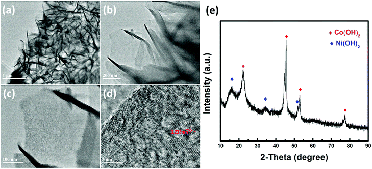 | ||
| Fig. 4 (a, b and c) TEM images and (d) HRTEM image of Co(OH)2, and (e) XRD pattern of the MF/Ni(II)–Co(OH)2 electrode material. | ||
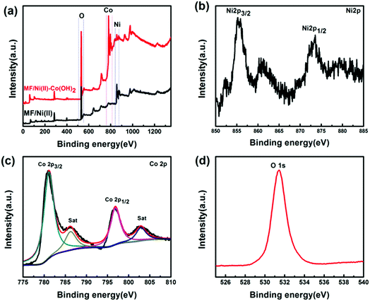
XPS analysis was carried out to characterize the surface chemical properties of the MF/Ni(II)–Co(OH)2 compressible electrode material. Fig. 5a presents the XPS survey spectra of the MF/Ni(II)–Co(OH)2 compressible electrode material and MF/Ni(II). Comparing the XPS spectra, the spectral diagram of the obtained compressible electrode material showed obvious Co characteristic peaks between 775 and 810 eV. In addition, the characteristic peaks of Ni between 850 and 885 eV are weaker relative to those of the MF/Ni(II) material. Fig. 5b displays the high-resolution XPS spectrum of Ni 2p of the MF/Ni(II)–Co(OH)2 compressible electrode material. As described in the image, the two typical single peaks related to Ni 2p3/2 and Ni1/2 are located at 855.43 and 873.07 eV, which can be ascribed to the presence of the Ni(OH)2 phase on the surface of the MF/Ni(II)–Co(OH)2 electrode material. Fig. 5c presents the high-resolution Co 2p spectra of the MF/Ni(II)–Co(OH)2 compressible electrode material. Generally, it is accepted that the oxidation state of Co cations is determined by the energy gap between the main peaks and the satellite peaks, and an energy gap of ∼6.0 eV is associated with Co2+, and an energy gap of 9–10 eV corresponds to Co3+.55–57 After Gaussian fitting, the Co 2p spectrum can be fitted into two spin–orbit bimodal and two vibrating satellites, which corresponds to the characteristics of Co2+ cations. The feature peaks of Co 2p3/2 and Co 2p1/2 are located at 781.10 eV and 796.84 eV, respectively, with a multiplet splitting energy of 15.74 eV, which demonstrated that Co exists as Co(OH)2 in the compressible electrode material. Fig. 5d displays the higher-solution O 1s spectra of the compressible electrode material; the binding energy in the O 1s spectrum from the compressible electrode material is located at 531.46 eV, which could be assigned to the Co–O–H bond. The shape and peak positions of the O 1s XPS spectrum are consistent with those of the Co(OH)2 previously reported in the literature.58,59 These results indicate the presence of Co(OH)2 in the compressible electrode materials prepared via the chemical deposition and electrochemical deposition method.
2.2. Electrochemical and compression performance of MF/Ni(II)–Co(OH)2
Fig. S5† presents the volume-specific capacitance changes of the MF/Ni(II)–Co(OH)2 electrode material with electrochemical deposition time. MF/Ni(II)–Co(OH)2 displays a volumetric capacitance of 224.66 mF cm−3 with an electrochemical deposition time of 5 min, and a volumetric capacitance of 454.25 mF cm−3 could be achieved with an electrochemical deposition time of 15 min, while the volumetric capacitance remains at 455.05 mF cm−3 with an electrochemical deposition time of 20 min, indicating that the volumetric capacitance is not significantly increased with the electrochemical deposition time from 15 to 20 min. Therefore, the electrochemical performance of the electrode material was determined using MF/Ni(II)–Co(OH)2 with an electrochemical deposition time of 15 min.The electrochemical properties of the as-prepared MF/Ni(II)–Co(OH)2 compressible electrode material were studied in a three-electrode system using 1 M KOH as the aqueous electrolyte, and the results are shown in Fig. 6. Fig. 6a presents the cyclic voltammetry (CV) curves of MF/Ni(II)–Co(OH)2 at scan rates from 5 to 100 mV s−1, and they exhibit a similar shape with the increase of scan rate, revealing the typical characteristics of faradaic pseudocapacitance. There is a group of oxidation–reduction peaks between 0 and 0.3 V due to the following faradaic reactions of Co(OH)2:60
| Co(OH)2 + OH− → CoOOH + H2O + e− | (3) |
| CoOOH + OH− → CoO2 + H2O + e− | (4) |
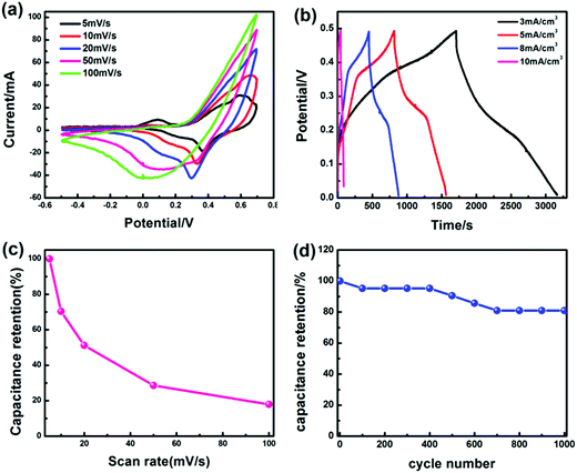 | ||
| Fig. 6 (a) The CV curves of the MF/Ni(II)–Co(OH)2 electrode material at different scan rates in 1 M KOH aqueous solution, (b) the GCD curves of the MF/Ni(II)–Co(OH)2 electrode material at different current densities, (c) the curve of specific capacitance values (calculated from eqn (6)) versus scan rate, (d) and the curve of specific capacitance values (calculated from eqn (5)) versus cycle number. | ||
The shape of the curve does not significantly change and the integral area of the curve is larger when the scan rate is increased to 100 mV s−1, which demonstrate that MF/Ni(II)–Co(OH)2 has good rate capability and highly reversible electrochemical reactions. Galvanostatic charge/discharge (GCD) curves were recorded at different current densities using a three-electrode setup in 1 M KOH electrolyte to evaluate the electrochemical performance of the MF/Ni(II)–Co(OH)2 compressible electrode material (Fig. 6b). There are two plateaus in the charge curve and one plateau in the discharge curve of the MF/Ni(II)–Co(OH)2 electrode material, which is consistent with the results of the CV curve. The GCD curves of MF/Ni(II)–Co(OH)2 exhibit a similar shape and the discharge time gradually decreases with increasing current density. The volumetric capacitance of the MF/Ni(II)–Co(OH)2 electrode material could reach 8.82 F cm−3 at a current density of 3 mA cm−3, calculated using the following equation:61
 | (5) |
 | (6) |
 is the integral area of the CV curve, V is the geometric volume of the working electrode, v is the scan rate, and ΔV is the operating potential window in the CV curves.
We investigated the cycling stability of the MF/Ni(II)–Co(OH)2 electrode material by a continuous charge–discharge test for 1000 cycles at a current density of 10 mA cm−3, as shown in Fig. S6.† As depicted in the figure, the discharge time was reduced from 21 s to 17 s after 1000 cycles, and the original shape of the GCD curve was nearly maintained. The curve of specific capacitance values (calculated from eqn (5)) versus cycle number is shown in Fig. 6d. The volume-specific capacitance of MF/Ni(II)–Co(OH)2 gradually decreased with the cycle number, exhibiting a volumetric capacitance retention of 80.95%, demonstrating the good cycling stability of MF/Ni(II)–Co(OH)2 as an electrode material.
Fig. S7† presents the electrochemical impedance spectroscopy (EIS) plot of the MF/Ni(II)–Co(OH)2 electrode material. It is generally accepted that the real axis intercept at high frequency represents the electrolyte resistance and the contact resistance between the active material and the current collector. The semicircle (depressed arc) corresponds to the charge transfer resistance, which is related to the rate capability. The slope of the straight line in the low frequency area is ascribed to the ion diffusion resistance.62–68 It can be observed that the MF/Ni(II)–Co(OH)2 single electrode material has a high frequency resistance of 5.97 Ω with a real axis intercept of the electrochemical impedance spectroscopy plot, which demonstrate the relatively better conductivity of the MF/Ni(II)–Co(OH)2 single electrode material. Moreover, a smaller semicircle can be observed in the electrochemical impedance spectroscopy plot of the MF/Ni(II)–Co(OH)2 single electrode material, which indicates the charge transfer resistance of the electrode material. Finally, a straight line can be seen in the low frequency area in the electrochemical impedance spectroscopy plot of the MF/Ni(II)–Co(OH)2 single electrode material, and it is ascribed to the ion diffusion resistance of the electrode material, which can indicate that the MF/Ni(II)–Co(OH)2 has relatively better ion diffusion performance. The above results indicate that the MF/Ni(II)–Co(OH)2 is a good electrode material due to its good rate capability and highly reversible electrochemical reaction, compression stability and conductivity.
The MF has an excellent three-dimensional interconnected network structure (Fig. 3a), resulting in good compression performance, and it can maintain its three-dimensional interconnected network structure after the electroless plating and electrochemical deposition process (Fig. 3g). Therefore, the obtained MF/Ni(II)–Co(OH)2 electrode material can maintain the superior compression performance of the original MF, and has a good capability to resist deformation during compression, causing a good pressure sensing reversibility. The CV curves at 50 mV s−1 and the GCD curves at 10 mA cm−3 (Fig. 7a and b) under different compression conditions (the compression ratio was adjusted according to the distance of fixture) were tested to evaluate the compression stability of the MF/Ni(II)–Co(OH)2 electrode material. As shown in Fig. 7a, redox peaks can be observed from the CV curves under different compression conditions, which indicate that oxidation–reduction reactions occurred in the electrode material during charging and also during discharging. The shapes of CV curves have not changed significantly under different compression conditions, and the electrode material can retain a specific capacitance of 93.81% even at 50% compression (Fig. 7b), which indicates the good compression stability of MF/Ni(II)–Co(OH)2 as a compressible electrode material. The GCD curves of the MF/Ni(II)–Co(OH)2 electrode material under different compression conditions are shown in Fig. 7c. There is no obvious change in the shape of the GCD curve under different compression conditions, which further demonstrates the compression stability of MF/Ni(II)–Co(OH)2. The volumetric capacitances of MF/Ni(II)–Co(OH)2 under different compression conditions were calculated from eqn (5) to evaluate its compression stability, and the curve is shown in Fig. 7d. It could be observed that the initial volume-specific capacitance of MF/Ni(II)–Co(OH)2 was well maintained under different compression conditions, exhibiting a volume-specific capacitance retention of 92.68% even under 50% compression, which revealed the remarkable compression stability of the MF/Ni(II)–Co(OH)2 electrode material. These conventional electrochemical tests show that the MF/Ni(II)–Co(OH)2 is an outstanding electrode material due to its good rate capability and highly reversible electrochemical reactions and compression stability.
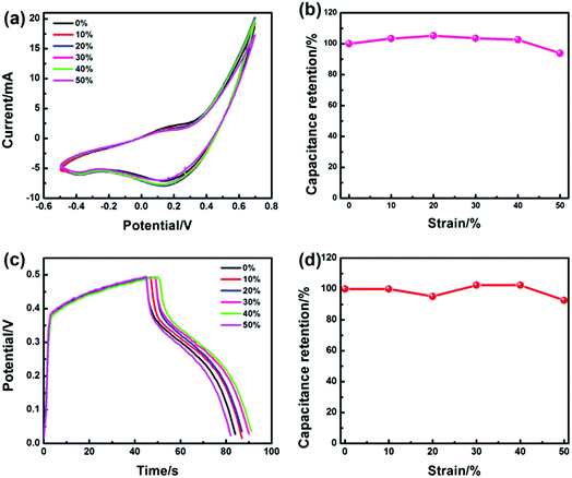 | ||
| Fig. 7 (a) The CV curves of the MF/Ni(II)–Co(OH)2 electrode material under different compression conditions, (b) the specific capacitance values (calculated from eqn (6)) versus compression, (c) the GCD curves of MF/Ni(II)–Co(OH)2 under different compression conditions, and (d) the specific capacitance values (calculated from eqn (5)) versus compression. | ||
TGA curves were recorded to calculate the loading mass of Co(OH)2 on MF. Fig. S8† presents the TGA curves of MF, MF/Ni(II) and MF/Ni(II)–Co(OH)2; the decomposition process of MF has two large weight loss intervals at 340–380 °C and 570–680 °C, and it completely decomposes at 680 °C, and the final residue mass percentage is 5.50%. For both MF/Ni(II) and MF/Ni(II)–Co(OH)2 as well, there are two weight loss stages corresponding to the MF skeleton. Furthermore, because Co(OH)2 is transformed into Co3O4 at 520 °C, the MF/Ni(II)–Co(OH)2 has an additional weight loss of 16.59% between 500 and 590 °C as compared with MF/Ni(II); as a result, the loading weight percentage of Co(OH)2 on MF is calculated to be 19.25%. Since the mass of the electrode material per cubic centimeter is 0.0183 g, the mass of Co(OH)2 per cubic centimeter of the electrode material is 0.0035 g. In addition, using the TGA curve and GCD curve, the mass capacitance of Co(OH)2 and MF/Ni(II)–Co(OH)2 was calculated to be 2505.68 and 481.97 F g−1, respectively.
Fig. 8 presents the morphology of MF/Ni(II)–Co(OH)2 and MF/Ni(II)–Co(OH)2 after electrochemical tests at different magnifications. As depicted in Fig. 8d, the 3D interconnected framework architecture of MF/Ni(II)–Co(OH)2 formed from numerous branched fibres was perfectly maintained after electrochemical testing, and the vertically aligned and closely stacked sheet-like Co(OH)2 on the surface of the branched fibers was retained very well after electrochemical testing (Fig. 8e and f), indicating the excellent cycling stability of the MF/Ni(II)–Co(OH)2 compressible electrode material.
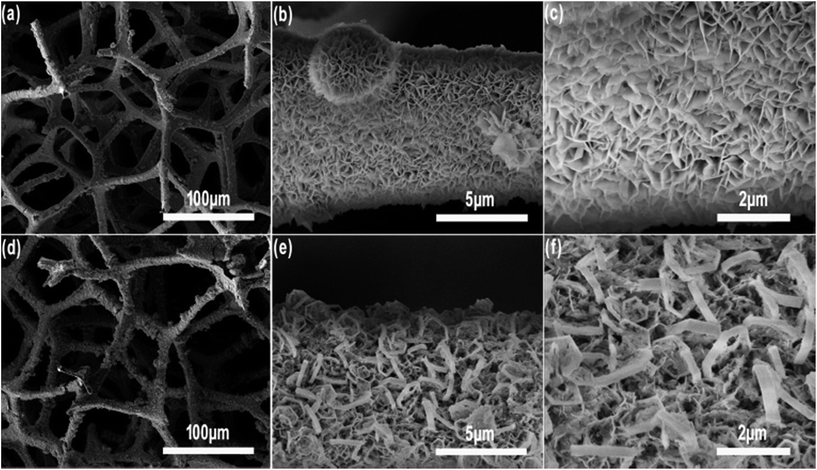 | ||
| Fig. 8 The SEM image of MF/Ni(II)–Co(OH)2 (a, b and c) before and (d, e and f) after electrochemical tests at different magnifications. | ||
2.3. Electrochemical performance of the device
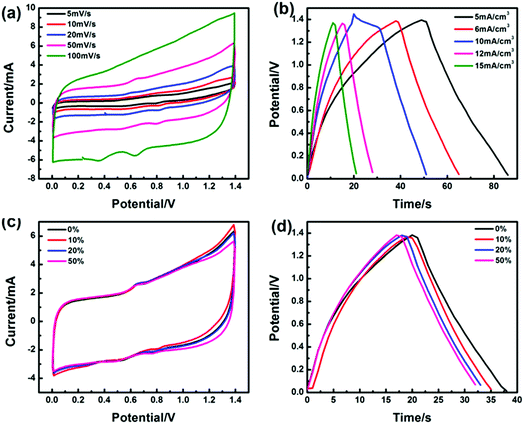
To evaluate the performance and reliability of MF/Ni(II)–Co(OH)2 as an electrode material for practical application, we assembled a simple asymmetrical all-solid compressible supercapacitor device composed of MF/Ni(II)–Co(OH)2 as an anode, C/Ni foam as a cathode, filter paper as a separator, and PVA–KOH as a gel electrolyte, as shown in Fig. 1. CV curves were recorded in a potential window of 1.4 V to assess the electrochemical properties of the device and they are shown in Fig. 9a. They exhibits a nearly rectangular mirror-image current response versus voltage reversal, and the shape of the CV curves exhibits no obvious distortion with the increase of scan rate, which indicate the ideal rate capability and excellent reversibility of the device. The GCD curves of the device at different current densities are illustrated in Fig. 9b, which shows a nearly symmetrical shape and the discharge time is decreased with the increase of current density. Furthermore, the volumetric capacitance of the device calculated using eqn (5) based on its GCD curve was 135.7 mF cm−3 at a current density of 5 mA cm−3, and it can maintain a volumetric capacitance of 86.84% even at a current density of 15 mA cm−3, again demonstrating an ideal capacitive behavior.It has been demonstrated that the MF/Ni(II)–Co(OH)2 electrode material has a good capability to resist deformation during compression, causing a good pressure sensing reversibility, and the assembled supercapacitor can recover its original state after compression (Fig. S9†). To further test the compression stability of the device, we examined its electrochemical properties under different compression conditions. Fig. 9c presents the CV curves of the device under various compression conditions of 0%, 10%, 20% and 50% with almost the same shape and integral area, indicating the good compression stability of the device. Similarly, the GCD curves of the device were recorded under various compression conditions (shown in Fig. 9d), and they exhibit a nearly symmetrical shape and the discharge time shows no significant change with various compression conditions, again demonstrating the good compression stability of the device. Furthermore, the volumetric capacitances of the device under different compression conditions were calculated from eqn (5) based on its GCD curve, and the specific capacitance values versus compression conditions curve is shown in Fig. S10,† which exhibits a volumetric capacitance retention of 84.21% even at 50% compression, demonstrating the good compression stability of the device.
We studied the cycling stability of the device by a continuous charge–discharge test in a potential window of 1.4 V for 1000 cycles at a current density of 10 mA cm−3 and the results are shown in Fig. S11.† It could be observed that the discharge time was reduced from 18 s to 17 s after 1000 cycles, which reveals a volumetric capacitance retention of 94.44%, demonstrating the good cycling stability of the obtained device. These superior results indicate that the MF/Ni(II)–Co(OH)2 is a promising candidate for high performance compressible energy storage devices.
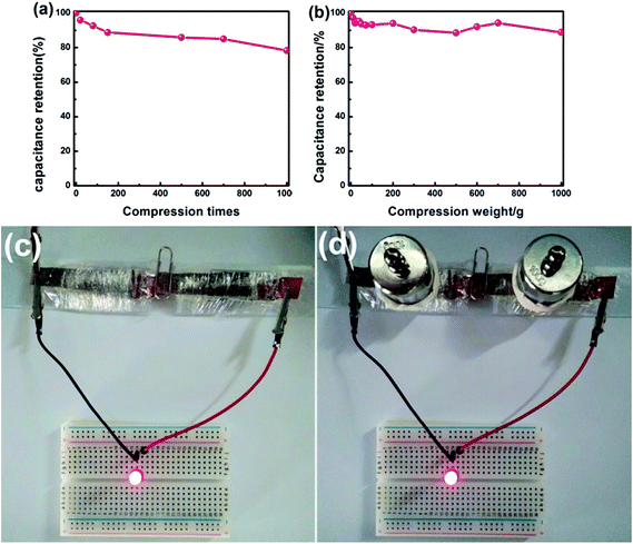
In order to test the compression stability of the assembled supercapacitor in use, the volumetric capacitance of the device was tested after different compression times. Fig. 10a presents the curve of volumetric capacitance values versus compression times, which shows that the volumetric capacitance values gradually decline with the increase of compression times (under a 100 g weight). From the 200th to the 700th compression, the capacitance value remains almost constant. After 1000 compressions, the device shows a volumetric capacitance retention of 78.33%, indicating the good compression stability of the device. The curve of volumetric capacitance values versus various compression weights is plotted in Fig. 10b, and it shows that the device can retain 89% of its initial volumetric capacitance under a compression weight of 1000 g, indicating that the device can withstand compression weights from 0 to 1000 g. These results again demonstrate the good compression stability.
In order to directly demonstrate the application of the device, we used it to power an LED light, and photos of the device and the LED light powered by the device are shown in Fig. 10c and d. The LED light can be powered by two supercapacitors in series as shown in Fig. 10c. To test the compression stability of the device, we applied a 100 g weight on each of the two supercapacitors. Fig. 10d displays the photos of the LED light powered by the compressed device. It can be found that the LED indicator still lit up regardless of the compression conditions compared with Fig. 10c. To further evaluate the compression stability of the device, we took a video of its working status (ESI-2†). As can be seen from the video, the device can work normally under repeated compression. This indicates the superior compression performance of the assembled device. These results further demonstrated that the MF/Ni(II)–Co(OH)2 is an excellent candidate as a compressible supercapacitor electrode material.
In general, the favorable performance of the assembled device can be ascribed to the following: (1) MF not only serves as a deposition substrate, but also provides a good compressible skeleton for a compressible electrode material; (2) MF/Ni(II) has high conductivity as a current collector, allowing rapid and effective electron transport; and (3) the flake-like Co(OH)2 is vertically aligned on the surface of MF/Ni(II), promoting ion diffusion between the electrode materials to achieve a highly efficient utilization of the active electrode material, resulting in the electrochemical stability and fast redox reaction of the device.
3. Experimental
3.1. Materials
All reagents were of pure grade and were directly used in the reaction without further purification. The melamine foam (MF) for experiments was provided by Outlook Company (Chengdu). Tin dichloride (SnCl2), palladium dichloride (PdCl2), citric acid monohydrate (C6H8O7·H2O) and N-methyl pyrrolidone (NMP) were purchased from Aladdin Industrial Co., Ltd.3.2. Fabrication of MF/nickel (MF/Ni(I))
A conventional electroless plating strategy was used to coat a Ni layer on the surface of MF to improve its conductivity. First of all, the MF was cut into a size of 1 × 2.5 × 0.5 cm3, and thoroughly washed with deionized (DI) water and ethanol. Then the MF was soaked in 0.1 M HCl solution for 30 minutes, and the surface residual HCl was washed with DI water. Then, the MF was immersed in a sensitizing solution (0.05 M SnCl2 and 0.12 M HCl) at room temperature for 30 min, and washed with DI water until neutral, causing the colloidal solution on the surface of SnCl2 to hydrolyze to form a Sn(OH)Cl colloid and adsorb on the MF surface. Next, after sensitizing and washing, the MF was immersed in an activation solution (100 μg mL−1 PdCl2 and 0.03 M HCl) at room temperature for 30 min and rinsed well with DI water. Pb2+ was reduced to Pb by Sn2+ and adsorbed on the surface of the MF substrate, so that electroless plating can be achieved. Finally, the treated MF was immersed in the electroless plating solution (0.05 M NiSO4·6H2O and 0.10 M C6H8O7·H2O), and ammonia water was added to maintain a pH of 10 simultaneously, and then 0.10 M NaH2PO2·H2O was slowly added to the above solution. Finally, the mixed solution was placed in a 70 °C water bath for 1 h. After the electroless plating process, the sample was thoroughly rinsed with DI water and dried in a 60 °C oven, yielding the conductive MF/Ni(I).513.3. Fabrication of MF/nickel (MF/Ni(II))
The electrochemical deposition method was used to fabricate the MF/Ni(II) for increasing the electrical conductivity of MF/Ni(I). The plating bath for this process consists of 0.15 M nickel(II) sulfate hexahydrate (NiSO4·6H2O) aqueous solution and 0.12 M ammonium chloride (NH4Cl) aqueous solution. And a three-electrode system was used for electrochemical nickel plating on the surface of MF/Ni(I), containing the MF/Ni(I) as the working electrode, and platinum tablets and Hg/HgCl as the counter electrode and the reference electrode, respectively. This process was performed on a Zahner Zennium electrochemical workstation. The MF/Ni(II) was prepared by the constant potential deposition method. To begin with, the MF/Ni(I) (size of 1 × 2.5 × 0.5 cm3) was immersed in the plating bath for 3 h, and then the electrochemical deposition process was performed with the constant potential deposition method at 2 V for 8 min. Finally, the as-prepared sample was rinsed several times with deionized water and dried at 60 °C in an oven to obtain the sample of MF/Ni(II).3.4. Fabrication of MF/Ni(II)–Co(OH)2
The MF/Ni(II)–Co(OH)2 was prepared by the constant potential deposition method (electrodeposition method). The deposition process was performed with a three-electrode system for electrochemical deposition of Co(OH)2 on the surface of MF/Ni(II), which contained the MF/Ni(II) as the working electrode, and platinum sheet and Hg/HgCl as the counter electrode and the reference electrode, respectively. The electrochemical plating solution of this process consists of 0.1 M cobaltous nitrate (Co(NO3)2·6H2O). Above all, the MF/Ni(II) (volume is 1 × 2.5 × 0.5 cm3) was immersed in the electrochemical plating solution for 3 h, and then the electrochemical deposition process was performed with the constant potential deposition method at 0.75 V for 15 min to fabricate the MF/Ni(II)–Co(OH)2 compressible electrode material. Finally, the as-prepared sample was rinsed several times with deionized water and dried at 60 °C in an oven. And the obtained sample was named MF/Ni(II)–Co(OH)2.523.5. Fabrication of the Ni/C foam electrode
Carbon black and PVDF were dispersed in NMP in a mass ratio of 9![[thin space (1/6-em)]](https://www.rsc.org/images/entities/char_2009.gif) :
:![[thin space (1/6-em)]](https://www.rsc.org/images/entities/char_2009.gif) 1, forming the mixed slurry. And then, the slurry was coated on the surface of the Ni foam material (the coating area is 1 × 1.5 cm2). Next, the electrode material was dried for 3 h in a 60 °C oven. The obtained sample was named Ni/C.
1, forming the mixed slurry. And then, the slurry was coated on the surface of the Ni foam material (the coating area is 1 × 1.5 cm2). Next, the electrode material was dried for 3 h in a 60 °C oven. The obtained sample was named Ni/C.
3.6. Assembly of the asymmetrical all-solid compressible supercapacitor
In order to further test the reliability of the as-prepared material as an electrode, we assembled a simple asymmetrical all-solid compressible supercapacitor, which contains Ni/C and MF/Ni(II)–Co(OH)2 electrode materials. First of all, 1.122 g KOH and 1.2 g PVA were dispersed in 20 mL DI water under magnetic stirring to prepare the gel electrolyte. Once the solution was mixed evenly, it was heated to 90 °C under magnetic stirring. The gel electrolyte could be obtained after stirring for 6 h. After that, the prepared MF/Ni(II)–Co(OH)2 and Ni/C electrode materials and the diaphragm were soaked in the gel electrolyte for 12 h. Finally, the electrode material and the diaphragm were assembled into a sandwich structure of the simple supercapacitor for testing the electrochemical performance.3.7. Material characterization and electrochemical performance testing
The morphologies of MF, MF/Ni(I), MF/Ni(II) and MF/Ni(II)–Co(OH)2 were characterized by Field Emission Scanning Electron Microscopy (FESEM, Nova Nano SEM 450) with an Energy Dispersive X-ray (EDX) detector, High Resolution Transmission Electron Microscopy (HRTEM, Tecnai G2 F20 S-Twin) and Polarizing Microscopy (PM, Axio Scope.A1). Furthermore, the surface of MF/Ni(II)–Co(OH)2 was nano-treated using the Focused Ion Beam (FIB) technique to observe the deposition of electrochemically active materials and conductive materials on the surface of MF with FESEM. X-ray photoelectron spectroscopy (XPS) (PHI 5800) was used to identify the surface chemical element composition and chemical states of the elements in the MF/Ni(II)–Co(OH)2. XRD patterns were obtained on a Rigaku Miniflex 600 diffractometer operated at 40 kV and 15 mA (Cu Kα radiation).The electrochemical performance of the MF/Ni(II)–Co(OH)2 electrode material was measured using an electrochemical workstation (Zennium, Zahner, Germany). The measurements were performed in a three-electrode system (MF/Ni(II)–Co(OH)2, a platinum plate, and a SCE were used as the working, counter, and reference electrodes, respectively), and the electrolyte was 1 M KOH aqueous solution. The CV curves were measured in the potential window of −0.2–0.5 V at scan rates from 10 to 100 mV s−1. The GCD curves of the MF/Ni(II)–Co(OH)2 electrode were acquired in a potential window of 0–0.5 V at current densities from 3 to 10 mA cm−3. Then, the electrochemical performance of the MF/Ni(II)–Co(OH)2 electrode material under different compression conditions was measured to evaluate its compression stability, and the compression ratio was adjusted according to the distance of the fixture. Finally, electrochemical impedance spectroscopy (EIS) was performed at 5 mV from 50 mHz to 50 kHz. In addition, the electrochemical performance of the assembled device was tested using a two-electrode system.
4. Conclusions
In summary, we successfully fabricated a MF/Ni(II)–Co(OH)2 electrode for compressible supercapacitors, which was prepared by electroless nickel plating and electrochemical deposition, and the commercial MF not only serves as a deposition substrate, but also provides a good compressible skeleton. The MF/Ni(II)–Co(OH)2 electrode with a uniform layer of electrochemically active material of flake-like Co(OH)2 vertically aligned on the surface of MF/Ni(II) is a free-standing, compressible electrode that exhibits excellent electrochemical performance, compression stability and cycling stability, displaying a high volumetric capacitance of 8.82 F cm−3 at a current density of 3 mA cm−3. It shows a volumetric capacitance retention of 80.95% after 1000 cycles and there is no obvious change of capacitance in different compression states. Furthermore, an all-solid-state compressible asymmetrical supercapacitor was assembled, and it contains the as-prepared MF/Ni(II)–Co(OH)2 electrode material and Ni/C electrode. And the electrochemical properties of the device were tested, revealing its good rate capability, cycling stability and compression stability. These favorable results indicate that the MF/Ni(II)–Co(OH)2 is a promising candidate for high performance compressible energy-storage systems.Conflicts of interest
There are no conflicts to declare.Acknowledgements
This work was financially supported by the National Key R&D Project from the Ministry of Science and Technology of China (2016YFA0202702), the National Natural Science Foundation of China (21571186), the Guangdong Provincial Key Laboratory (2014B030301014), the Youth Innovation Promotion Association (2017411), and the “Guangdong TeZhi plan” Youth Talent of Science and Technology (2014TQ01C102).Notes and references
- P. Simon and Y. Gogotsi, Nat. Mater., 2008, 7, 845 CrossRef PubMed.
- J. H. Choi, C. Lee, S. Cho, G. DaeMoon, B. Sukim, H. Chang and H. DongJang, Carbon, 2018, 132, 16–24 CrossRef.
- C. Y. Yang, M. Q. Sun and H. B. Lu, Chem.–Eur. J., 2018, 24, 6169 CrossRef PubMed.
- L. J. Ren, G. N. Zhang, J. Lei, Y. Wang and D. W. Hu, J. Colloid Interface Sci., 2018, 512, 300 CrossRef PubMed.
- V. Strauss, K. Marsh, M. D. Kowal, M. El-Kady and R. B. Kaner, Adv. Mater., 2018, 30, 1704449 CrossRef PubMed.
- M. Ulaganathan, M. Maharjan, Q. Y. Yan, V. Aravindan and S. Madhavi, Chem.–Asian J., 2017, 12, 2127 CrossRef PubMed.
- P. Simon and Y. Gogotsi, Acc. Chem. Res., 2013, 46, 1094 CrossRef PubMed.
- G. W. Huang, N. Li, Y. Du, Q. P. Feng, H. M. Xiao, X. H. Wu and S. Y. Fu, ACS Appl. Mater. Interfaces, 2018, 10, 723 CrossRef PubMed.
- G. Nagaraju, S. C. Sekhar, L. K. Bharat and J. S. Yu, ACS Nano, 2017, 11, 10860 CrossRef PubMed.
- R. S. Guo, J. T. Chen, B. J. Yang, L. Y. Liu, L. J. Su, B. S. Shen and X. B. Yan, Adv. Funct. Mater., 2017, 1702394 CrossRef.
- X. Liang, K. W. Nie, X. Ding, L. Q. Dang, J. Sun, F. Shi, H. Xu, R. B. Jiang, X. X. He, Z. H. Liu and Z. B. Lei, ACS Appl. Mater. Interfaces, 2018, 10, 10087 CrossRef PubMed.
- D. Wu, Y. Liu, Y. Wu, B. Tan and Z. L. Xie, Dalton Trans., 2018, 47, 5961 RSC.
- L. Li, Z. Lou, D. Chen, K. Jiang, W. Han and G. Z. Shen, Small, 2017, 1702829 CrossRef PubMed.
- D. J. Li, S. Lei, Y. Y. Wang, S. M. Chen, Y. Kang, Z. G. Gu and J. Zhang, Dalton Trans., 2018, 47, 5558 RSC.
- Y. Liu, B. B. Huang, X. X. Lin and Z. L. Xie, J. Mater. Chem. A, 2017, 5, 13009 RSC.
- K. Xiao, L. X. Ding, G. X. Liu, H. B. Chen, S. Q. Wang and H. H. Wang, Adv. Mater., 2016, 28, 5997 CrossRef PubMed.
- K. L. VanAken, C. R. Pérez, Y. Oh, M. Beidaghi, Y. J. Jeong, M. Islam and Y. Gogotsi, Nano Energy, 2015, 15, 662 CrossRef.
- D. G. Jiang, C. W. Li, W. R. Yang, J. Z. Zhang and J. Q. Liu, J. Mater. Chem. A, 2017, 5, 18684 RSC.
- B. S. Yin, S. W. Zhang, Q. Q. Ren, C. Liu, K. Ke and Z. B. Wang, J. Mater. Chem. A, 2017, 5, 24942 RSC.
- K. Xiao, Y. H. Zeng, J. Long, H. B. Chen, L. X. Ding, S. Q. Wang and H. H. Wang, ACS Appl. Mater. Interfaces, 2017, 9, 15477 CrossRef PubMed.
- Y. Y. Zhang, Z. Zhen, Z. L. Zhang, J. C. Lao, J. Q. Wei, K. L. Wang, F. Y. Kang and H. W. Zhu, Electrochim. Acta, 2015, 157, 134 CrossRef.
- X. F. Zhang, J. Q. Zhao, X. He, Q. Y. Li, C. H. Ao, T. Xia, W. Zhang, C. H. Lu and Y. L. Deng, Carbon, 2018, 127, 236 CrossRef.
- P. X. Li, C. Y. Kong, Y. Y. Shang, E. Z. Shi, Y. T. Yu, W. Z. Qian, F. Wei, J. Q. Wei, K. L. Wang, H. W. Zhu, A. Y. Cao and D. H. Wu, Nanoscale, 2013, 5, 8472 RSC.
- E. K. Feng, G. F. Ma, H. Peng, F. T. Hua, W. Tang and Z. Q. Lei, New J. Chem., 2017, 41, 13347 RSC.
- P. X. Li, E. Z. Shi, Y. B. Yang, Y. Y. Shang, Q. Y. Peng, S. T. Wu, J. Q. Wei, K. L. Wang, H. W. Zhu, Q. Yuan, A. Y. Cao and D. H. Wu, Nano Res., 2014, 7, 209 CrossRef.
- X. He, W. Y. Yang, X. L. Mao, L. Xu, Y. J. Zhou, Y. Chen, Y. T. Zhao, Y. J. Yang and J. H. Xu, J. Power Sources, 2018, 376, 138 CrossRef.
- Y. Liu, X. M. Zhou, R. Liu, X. L. Li, Y. Bai and G. H. Yuan, New J. Chem., 2017, 41, 14906 RSC.
- Y. P. Zhao, M. P. Li, S. Y. Liu and M. F. Islam, ACS Appl. Mater. Interfaces, 2017, 9, 23810 CrossRef PubMed.
- P. X. Li, Y. B. Yang, E. Z. Shi, Q. C. Shen, Y. Y. Shang, S. T. Wu, J. Q. Wei, K. L. Wang, H. W. Zhu, Q. Yuan, A. Y. Cao and D. H. Wu, ACS Appl. Mater. Interfaces, 2014, 6, 5228 CrossRef PubMed.
- X. P. Cheng, X. C. Gui, Z. Q. Lin, Y. J. Zheng, M. Liu, R. Z. Zhan, Y. Zhu and Z. K. Tang, J. Mater. Chem. A, 2015, 3, 20927 RSC.
- H. Tong, S. H. Yue, L. Lu, F. Q. Jin, Q. W. Han, X. G. Zhang and J. Liu, Nanoscale, 2017, 9, 16826 RSC.
- C. H. Wang, X. D. He, Y. Y. Shang, Q. Y. Peng, Y. Y. Qin, E. Z. Shi, Y. B. Yang, S. T. Wu, W. J. Xu, S. Y. Du, A. Y. Cao and Y. B. Li, J. Mater. Chem. A, 2014, 2, 14994 RSC.
- S. B. Ye and J. C. Feng, ACS Appl. Mater. Interfaces, 2014, 6, 9671 CrossRef PubMed.
- Y. Zhao, J. Liu, Y. Hu, H. H. Cheng, C. G. Hu, C. C. Jiang, L. Jiang, A. Y. Cao and L. T. Qu, Adv. Mater., 2013, 25, 591 CrossRef PubMed.
- P. Lv, X. Tang, R. L. Zheng, X. B. Ma, K. H. Yu and W. Wei, Nanoscale Res. Lett., 2017, 12, 630 CrossRef PubMed.
- P. Lv, X. Tang, J. J. Yuan and C. L. Ji, Mater. Res. Express, 2017, 4, 115602 CrossRef.
- Y. H. Chang, G. Y. Han, Y. Z. Chang, Y. M. Xiao, W. T. Hou and W. Zhou, J. Alloys Compd., 2017, 708, 1206 CrossRef.
- K. Xiao, L. X. Ding, G. X. Liu, H. B. Chen, S. Q. Wang and H. H. Wang, Adv. Mater., 2016, 28, 5997 CrossRef PubMed.
- Z. Q. Sun, T. Liao, Y. H. Dou, S. M. Hwang, M. S. Park, L. Jiang, J. H. Kim and S. X. Dou, Nat. Commun., 2014, 5, 3813 CrossRef PubMed.
- X. Ge, C. D. Gu, X. L. Wang and J. P. Tu, J. Phys. Chem. C, 2014, 118, 911 CrossRef.
- B. R. Jia, M. L. Qin, S. M. Li, Z. L. Zhang, H. F. Lu, P. Q. Chen, H. Y. Wu, X. Lu, L. Zhang and X. H. Qu, ACS Appl. Mater. Interfaces, 2016, 8, 15582 CrossRef PubMed.
- K. Ding, X. Zhang, J. P. Li, P. Yang and X. Cheng, CrystEngComm, 2017, 19, 5780 RSC.
- H. X. Wang, W. Zhang, N. E. Drewett, H. B. Zhang, K. K. Huang, S. H. Feng, X. L. Li, J. Kim, S. Yoo, T. Deng, S. J. Liu, D. Wang and W. T. Zheng, J. Microsc., 2017, 267, 34 CrossRef PubMed.
- B. Rezaei, A. R. T. Jahromi and A. A. Ensafi, J. Alloys Compd., 2017, 42, 16538 Search PubMed.
- T. T. Cui, Y. T. Zhao, Y. Qian, Y. l. Shao, M. T. Fan, J. J. Feng, W. H. Wu and G. X. Tong, Mater. Chem. Phys., 2017, 193, 371 CrossRef.
- H. Pang, X. R. Li, Q. X. Zhao, H. G. Xue, W. Y. Lai, Z. Hu and W. Huang, Nano Energy, 2017, 35, 138 CrossRef.
- Z. Q. Niu, W. Y. Zhou, X. D. Chen, J. Chen and S. S. Xie, Adv. Mater., 2015, 27, 6002 CrossRef PubMed.
- W. Chen, R. B. Rakhi and H. N. Alshareef, J. Mater. Chem., 2012, 22, 14394 RSC.
- D. P. Dubal, J. G. Kim, Y. Kim, R. Holze, C. D. Lokhande and W. B. Kim, Energy Technol., 2014, 2, 325 CrossRef.
- Z. Y. Yang, L. J. Jin, G. Q. Lu, Q. Q. Xiao, Y. X. Zhang, L. Jing, X. X. Zhang, Y. M. Yan and K. N. Sun, Adv. Funct. Mater., 2014, 24, 3917 CrossRef.
- L. C. Zhang, P. L. Zhu, F. R. Zhou, W. J. Zeng, H. B. Su, G. Li, J. H. Gao, R. Sun and C. P. Wong, ACS Nano, 2016, 10, 1273 CrossRef PubMed.
- L. C. Zhang, X. C. Yu, P. L. Zhu, F. R. Zhou, G. Li, R. Sun and C. P. Wong, Sustainable Energy Fuels, 2018, 2, 147 RSC.
- T. Zhao, H. Jiang and J. Ma, J. Power Sources, 2011, 196, 860 CrossRef.
- H. Liu, Q. Xue, J. S. Zhao and Q. Zhang, Electrochim. Acta, 2018, 260, 330 CrossRef.
- S. B. Wang, Y. D. Hou and X. C. Wang, ACS Appl. Mater. Interfaces, 2015, 7, 4327 CrossRef PubMed.
- S. B. Wang, B. Y. Guan and X. W. Lou, Energy Environ. Sci., 2018, 11, 306 RSC.
- W. F. Wei, W. X. Chen and D. G. Ivey, Chem. Mater., 2008, 20, 1941 CrossRef.
- C. Chen, M. Cho and Y. Lee, J. Mater. Sci., 2015, 50, 6491 CrossRef.
- J. K. Chang, C. M. Wu and I. W. Sun, J. Mater. Chem., 2010, 20, 3729–3735 RSC.
- G. C. Lau, N. A. Sather, H. Sai, E. M. Waring, E. D. Yehiely, L. Barreda, E. A. Beeman, L. C. Palmer and S. I. Stupp, Adv. Funct. Mater., 2018, 28, 1702320 CrossRef.
- J. W. Lee, A. S. Hall, J. D. Kim and T. E. Mallouk, Chem. Mater., 2012, 24, 1158 CrossRef.
- X. Zhang, J. T. Jiang, Y. Chen, K. Cheng, F. Yang, J. Yan, K. Zhu, K. Ye, G. L. Wang, L. M. Zhou and D. X. Cao, Chem. Eng. J., 2018, 335, 321 CrossRef.
- J. X. Feng, S. H. Ye, A. L. Wang, X. F. Lu, Y. X. Tong and G. R. Li, Adv. Funct. Mater., 2014, 24, 7093 CrossRef.
- X. Bai, Q. Liu, Z. T. Lu, J. Y. Liu, R. R. Chen, R. M. Li, D. L. Song, X. Y. Jing, P. L. Liu and J. Wang, ACS Sustainable Chem. Eng., 2017, 5, 9923 CrossRef.
- C. M. Zhao, F. Ren, Y. Cao, X. X. Xue, X. Y. Duan, H. R. Wang and L. M. Chang, J. Phys. Chem. Solids, 2018, 112, 54 CrossRef.
- L. Y. Jiang, Y. W. Sui, J. Q. Qi, Y. Chang, Y. Z. He, Q. K. Meng, F. X. Wei, Z. Sun and Y. X. Jin, Appl. Surf. Sci., 2017, 426, 148 CrossRef.
- M. Lian, X. M. Wu and Q. Q. Wang, Mater. Lett., 2017, 207, 16 CrossRef.
- M. Suksomboon, J. Khuntilo, S. Kalasina, P. Suktha, J. Limtrakul and M. Sawangphruk, Electrochim. Acta, 2017, 252, 91 CrossRef.
Footnote |
| † Electronic supplementary information (ESI) available: I–t and GCD Nyquist curves, and digital photos, SEM images, EDX spectrum, elemental mapping, CV curves for different deposition times and TGA curve of the electrode material, and schematic for the compression process, specific capacitance values, GCD cycle curve and a video of the device. Comparison of the Co(OH)2 and MF based supercapacitors. See DOI: 10.1039/c8se00409a |
| This journal is © The Royal Society of Chemistry 2018 |

