 Open Access Article
Creative Commons Attribution 3.0 Unported Licence
Radiation-grafted anion-exchange membranes: the switch from low- to high-density polyethylene leads to remarkably enhanced fuel cell performance†
Lianqin
Wang
 a,
Xiong
Peng
b,
William E.
Mustain
 b and
John R.
Varcoe
 *a
*a
aDepartment of Chemistry, The University of Surrey, Guildford, Surrey GU2 7XH, UK. E-mail: lilianqinwang@gmail.com; j.varcoe@surrey.ac.uk
bDepartment of Chemical Engineering, University of South Carolina, Columbia, SC 29208, USA
First published on 26th April 2019
Abstract
Herein we detail the development of a new high-density polyethylene-(HDPE)-based radiation-grafted anion-exchange membrane (RG-AEM) that achieves a surprisingly high peak power density and a low in situ degradation rate (with configurations tailored to each). We also show that this new AEM can be successfully paired with an exemplar non-Pt-group cathode.
Broader contextA primary motivation for the development of anion-exchange membrane (AEM) fuel cells (AEMFCs) is the broader range of sustainable, non-precious-metal catalysts that are feasible; if costs are lowered enough, AEMFCs would be deployable in a range of stationary power sectors (e.g. back-up and off-grid). However, as the performance of AEMFCs typically drop when Pt-based electrodes are replaced with non-Pt types, it is essential that the highest performing polyelectrolytes are developed, both membranes and ionomers (the latter incorporated to impart ionic conductivity in the electrodes). The findings with the high conductivity AEM reported herein will also be of interest to developers of AEMs for metal–air and redox-flow batteries, electrolysers (both H2O → H2 and CO2 → high-value chemicals and fuels), and salinity gradient power. |
It is critical that anion exchange membranes (AEM), developed for use in anion exchange membrane fuel cells (AEMFCs), can support both high power outputs and in situ durability. The literature shows a dearth of options that have an acceptable combination of both, which is mandatory to push AEMFCs closer to widescale implementation and commercialisation.
In recent years, significant progress has been made in the development of AEMs generally,1 and RG-AEMs specifically.2 RG-AEMs produced via a high dose rate electron-beam modification of low density polyethylene (LDPE) films2 have helped to advance the field, by both allowing for an enhanced understanding on how AEMs behave in AEMFCs, as well as their ability to support high H2 fuel cell performances (>1.0 W cm−2 at >60 °C with non-Pt cathodes).3,4 This performance was possible because such LDPE-based RG-AEMs have high conductivities, and kinetically fast water transport characteristics (that extends the region of mass transport power losses to higher current densities). However, a limiting aspect of thin LDPE-based RG-AEMs films are their modest mechanical properties under stress (Table 1), which needs to be improved for commercial applications. In this respect, the use of high-density polyethylene (HDPE) was hypothesised to be a promising avenue of research, especially as prior reports suggest that HDPE can be used to make viable RG-AEMs5 using low dose rate gamma ray methods (Sproll et al.6a report low dose rates lead to a lower concentration of longer grafted chains, which leads to poorer performance characteristics).
| LDPE-AEM | HDPE-AEM | |
|---|---|---|
| a Ion-exchange capacity, IEC = mmol Cl− per g(dry RG-AEM, Cl− form). b Hydrated AEM thickness at room temperature (Cl− form). c Dehydrated AEM thickness at room temperature (Cl− form). d Through-plane swelling (= 100 × (thyd − tdehyd)/tdehyd). e Propagated errors. f Gravimetric water uptake (Cl− form) at room temperature (= 100 × (mhyd − mdehyd)/mdehyd, where m = mass/g). g The number of water molecules per Cl− anion in the fully hydrated AEM, calculated as: λH2O = WU/(100 × 18.02 × IEC). h The 4-probe (in-plane) OH− conductivity in a flowing 100% relative humidity N2 atmosphere,4 based on the method first reported by Ziv and Dekel.8 i Tensile properties of the Cl− form RG-AEMs (errors within 25%) in the ambient atmosphere. | ||
IEC/mmol g−1![[thin space (1/6-em)]](https://www.rsc.org/images/entities/char_2009.gif) a a |
2.54 ± 0.21 | 2.44 ± 0.04 |
| t hyd/μmb | 28 ± 1 | 29 ± 1 |
| t dehyd/μmc | 22 ± 2 | 21 ± 1 |
| TPS (%)d | 27 ± 10e | 38 ± 7e |
| WU (%)f | 149 ± 16 | 155 ± 15 |
| λ H2O | 32 ± 3e | 35 ± 2e |
σ(OH−, 25 °C, RH = 100%)/mS cm−1![[thin space (1/6-em)]](https://www.rsc.org/images/entities/char_2009.gif) h h |
100 ± 7 | 121 ± 3 |
σ(OH−, 80 °C, RH = 100%)/mS cm−1![[thin space (1/6-em)]](https://www.rsc.org/images/entities/char_2009.gif) h h |
208 ± 6 | 214 ± 2 |
| Stress at break (MPa)i | 23 | 35 |
| Elongation at break (%)i | 69 | 283 |
We report for the first time a HDPE RG-AEM fabricated using a high dose rate electron-beaming method (amenable to large batch production), with comparable properties to a similarly fabricated LDPE RG-AEM, but with improved mechanical properties, fuel cell performance, and operational stability.
The RG-HDPE AEMs were fabricated and characterised using the methods detailed in our previous publications.2,4,7 In summary, HDPE films (10 μm thickness, ET321010, Goodfellow UK), and LDPE films (15 μm, ET311115, Goodfellow UK) were subjected to 100 kGy absorbed dose in air (peroxidation method) using a 4.5 MeV dynamic continuous electron-beam unit (STERIS Applied Sterilization Technologies, South Marston, UK, 10 kGy absorbed dose per rapid pass of the films under the e-beam). The e-beam irradiated films were then stored in a freezer at −40 °C until use.
Weighted e-beam irradiated films were grafted with vinylbenzyl chloride (VBC, mixture of 3- and 4-isomers, Sigma-Aldrich product 338729, no removal of any inhibitors) by immersion in a N2-purged aqueous solution of VBC (5 vol% with the further addition of 1 vol% octyl-2-pyrrolidone dispersant): 6 h grafting at 40 °C for LDPE and 4 h at 50 °C for HDPE. After thorough washing with toluene and drying at 16 h at room temperature, the grafted membranes were weighed before being submerged in aqueous trimethylamine (45 wt%) for 24 h. After subsequent multiple room temperature washings with ultrapure water (UPW, 18.2 MΩ cm), heating in UPW for 1 h at 60 °C, ion-exchange by immersion in aqueous NaCl (1 mol dm−3, immersion for 1 h in 3× fresh solutions), and further washing in UPW (until no traces of free Cl− remained), the Cl− anion forms of the LDPE- and HDPE-based RG-AEMs were recovered (heron designated LDPE-AEM and HDPE-AEM, respectively).
For the grafting stage (pre-amination), we observed that the irradiated HDPE films could be grafted more repeatedly after storage at −40 °C for at least 6 months after beaming compared to the LDPE (Fig. 1): this is hypothesised to be due to differences in radical-based self-crosslinking rates during cold-storage.6b,c This more predictable “shelf-life” is clearly beneficial for repeated batch fabrication over 6 months (with predictable properties).
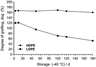 | ||
| Fig. 1 Degree of grafting (dog) of poly(VBC)-grafted membranes made from e-beamed LDPE and HDPE films that were stored (pre-grafted) at −40 °C for increasing periods of time. The dog (%) was calculated as: dog = 100 × (mg − mi)/mi (where mi was the mass of the e-beamed pre-grafted film and mg was the mass of the (pre-aminated) VBC-grafted membrane).7 | ||
The key properties of the two RG-AEMs are summarised in Table 1. The HDPE RG-AEM exhibited very similar ex situ properties to the LDPE RG-AEM: ion-exchange capacity (IEC), hydrated thickness, water-uptake, and OH− conductivity. Both RG-AEMs (OH− form) also similarly retained their conductivities in a flowing humidified N2 atmosphere at 80 °C (Fig. 2); the loss of conductivity was only (8 ± 1)% after 500 h for both. Comparing the Raman spectra before and after 500 h, Fig. 3 shows only minor RG-HDPE degradation, in good agreement with the reduction in conductivity during that time.
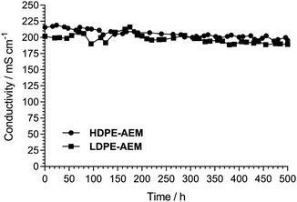 | ||
| Fig. 2 Changes in OH− conductivity of the RG-AEMs when placed in a flowing relative humidity RH = 100% N2 atmosphere at 80 °C for 500 h. Method discussed in detail in ref. 4 (where the LDPE-AEM data was first reported). | ||
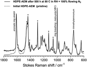 | ||
| Fig. 3 The Raman spectra of the HDPE-AEM before and after the 500 h test presented in Fig. 2. A ThermoFisher DRX Raman microscope (532 nm laser) was used. Key diagnostic peaks4 are labelled; * = HDPE-derived peaks. The spectra were normalised to the trimethylammonium peak at 753 cm−1 to aid visual comparison. | ||
However, where the HDPE-AEM appears much more desirable compared to the LDPE-AEM was its tensile properties. The break stress of the HDPE-AEM was 52% greater than the LDPE AEM and it also showed an enhanced ability to stretch without failing. This was accomplished without having to increase the thickness of the final hydrated AEMs (achieved just by using a different substrate). The use of thin membranes is desirable as they enable fast water transport, meaning that a higher current density can be supported since high AEMFC performance relies heavily on the back-diffusion of water from the anode to the cathode.9–11
Fig. 4 shows the beginning-of-life AEMFC performances at 80 °C for cells operated with HDPE- and LDPE-AEMs using identical electrodes and benchmark fuel-cell-grade Pt-based catalysts (using the Surrey group's standard fuel cell testing protocols, which have been detailed extensively in recent publications2,4 and allows us to maintain a local database of relative performances of different AEMs). Despite the LDPE-AEM and HDPE-AEM exhibiting similar ex situ thicknesses, water uptakes, and conductivities, the HDPE-AEM yielded a significantly higher H2/O2 AEMFC performance: the HDPE-AEM exhibited a peak power density of 2.55 W cm−2 at 80 °C (cf. 2.01 W cm−2 for the LDPE-AEM) with zero back-pressure gas feeds (with only ca. 0.2 bar pressure drops).
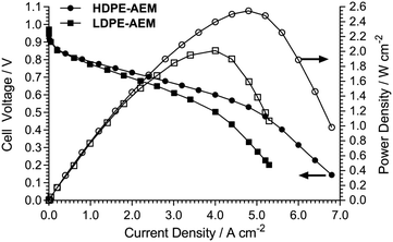 | ||
| Fig. 4 H2/O2 AEMFC comparison tests (80 °C) for the RG-AEMs. Full details on the test conditions used are given in ref. 4 with the following summary data (the only variable in these tests was the RG-AEM used): PtRu/C anodes (50 wt% Pt and 25 wt% Ru) with a Pt-loading of 0.4 mg cm−2; Pt/C cathode (40 wt% Pt) with a Pt-loading of 0.4 mg cm−2; catalyst inks contained 20 wt% radiation-grafted ETFE-based anion-exchange ionomer powder (IEC = 1.90 ± 0.06 mmol g−1) and were sprayed directly onto Toray TGP-H-60 (10 wt% PTFE-treated) gas diffusion substrate; the H2/O2 gases were supplied at 1 dm−3 min−1 at RH = 92% with no back-pressure applied. This galvanostatic data was collected using a Scribner 850E fuel cell tester. | ||
This is a dramatic demonstration of the findings by Sproll et al. related to the development of RG-proton-exchange membranes (RG-PEM),12 who reported that conductivities, water uptakes, and resulting fuel cell (PEMFC) performances strongly depend on the micro-structure of the ETFE-base films used. The use of nominally identical base ETFE films (from two suppliers), differing only in microstructure, resulted in critical differences in the final membranes: larger crystalline sizes led to enhanced RG-PEM conductivities and durabilities of the resulting PEMFCs. The only significant variable in our comparison experiments (Fig. 4) was the starting base-material used. DSC experiments show that the supplied HDPE film had a crystallinity of 57% (cf. 70–80% in supplier literature, HDPE is defined as having a low degree of branching), while the LDPE film had a lower crystallinity of 47% (ca. 50% in the supplier literature, LDPE is defined as having a high degree of branching): these initial differences are clearly highly significant to the performances of the resulting AEMFCs. This also serves as a warning: a correctly selected combination of electron-beaming dose-rate and supplier (grade/additives) of base-material will be critical to any final, reproducible commercial production effort.
As there is no significant difference between the OH− conductivity or thicknesses of the HDPE-AEM and LDPE-AEM, we hypothesise that the improved performance is due to the enhanced water transport from the anode and cathode in the operating fuel cells9–11 and this must be due to a change in the nanomorphology or microstructure between the LDPE- and HDPE-AEM. This hypothesis needs to be rigorously tested and so we are in the process of planning a series of quasi-elastic neutron scattering (QENS) and small-angle neutron scattering (SANS) experiments13 to probe the ion-dynamics and nanomorphology in much more detail (comparing the new HDPE-based RG-AEM to both prior-art LDPE-2,4 and ETFE-based7 RG-AEMs). These results will be reported in a future, specific research paper.
These high performances were independently reproduced at the University of South Carolina with their own benchmarking parameters. The anode was PtRu(2![[thin space (1/6-em)]](https://www.rsc.org/images/entities/char_2009.gif) :
:![[thin space (1/6-em)]](https://www.rsc.org/images/entities/char_2009.gif) 1)/C with a 0.7 mg cm−2 PtRu loading; the cathode was Pt/C with 0.6 mg cm−2 Pt loading; both catalyst layers contained 20 wt% radiation-grafted ETFE-based anion-exchange ionomer powder (IEC = 1.24 ± 0.06 mmol g−1) and were sprayed onto Toray TGP-H-60 carbon-paper GDEs containing 5 wt% PTFE wet-proofing. The peak power density was 2.5 W cm−2 with a cell at 80 °C operating with H2/O2 reacting gases. A 2.4 W cm−2 peak power density was also achieved in the same cell at an advantageously lower temperature of 70 °C (gases supplied at 1 dm3 min−1 with an anode dew-point of 60 °C and cathode dew-point of 68 °C). The peak power density of this latter cell at 70 °C with CO2-free air at the cathode was 1.1 mW cm−2.
1)/C with a 0.7 mg cm−2 PtRu loading; the cathode was Pt/C with 0.6 mg cm−2 Pt loading; both catalyst layers contained 20 wt% radiation-grafted ETFE-based anion-exchange ionomer powder (IEC = 1.24 ± 0.06 mmol g−1) and were sprayed onto Toray TGP-H-60 carbon-paper GDEs containing 5 wt% PTFE wet-proofing. The peak power density was 2.5 W cm−2 with a cell at 80 °C operating with H2/O2 reacting gases. A 2.4 W cm−2 peak power density was also achieved in the same cell at an advantageously lower temperature of 70 °C (gases supplied at 1 dm3 min−1 with an anode dew-point of 60 °C and cathode dew-point of 68 °C). The peak power density of this latter cell at 70 °C with CO2-free air at the cathode was 1.1 mW cm−2.
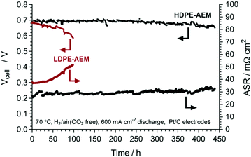
Given the above data, a HDPE-AEM membrane-electrode assembly (MEA) was tested over 440 h at 600 mA cm−2 constant current discharge in a H2/air(CO2 free) AEMFC at 70 °C (Fig. 5, caption details the test parameters used).‡ Both the cell voltage and area specific resistance (ASR) were recorded throughout the duration of the test. The ASR increased by 8.2 ± 0.2 μΩ cm2 h−1 (95% confidence intervals, linear regression, R2 = 0.55) during testing, indicating an excellent retention of the conductivities of the cell components. Secondly, over the 440 h of continuous operation, there was 7% voltage degradation when comparing the first and final data points (0.70 V → 0.67 V), while a degradation rate of 68 ± 1 μV h−1 (95% confidence intervals, n = 15![[thin space (1/6-em)]](https://www.rsc.org/images/entities/char_2009.gif) 386 data points, R2 = 0.54) was estimated using a simple linear regression. At this stage we do not know the relative rates of degradation of each component (ionomer, catalyst, AEM) as this can’t be elucidated using such a simple in situ durability test. This will be studied in much more detail in the future using a variety of more advanced techniques including operando tomography.
386 data points, R2 = 0.54) was estimated using a simple linear regression. At this stage we do not know the relative rates of degradation of each component (ionomer, catalyst, AEM) as this can’t be elucidated using such a simple in situ durability test. This will be studied in much more detail in the future using a variety of more advanced techniques including operando tomography.
We also conducted an initial 100 h test with the LDPE-AEM for comparison (Fig. 5). This shows a much more rapid degradation rate of 790 ± 10 μV h−1 (95% confidence intervals, n = 3530 data points, R2 = 087), which is why we terminated the test early. The failure mechanism with the LDPE-AEM clearly involved an increase in in situ ASR (38 → 52 mΩ cm2).
With regards to commercialisation, catalyst cost and sustainability are important factors that must be considered when operating these devices. Due to the generally lower intrinsic activity of non-Pt catalysts for the oxygen reduction reaction in alkaline media, there is typically a 30–50% performance drop when they are applied to AEMFC cathodes. For most non-RG-AEMs, non-Pt-catalyst containing AEMFCs are routinely reported with power densities below 1 W cm−2.14,15 We replaced the Pt/C cathode from Fig. 4 with an exemplar non-Pt-group cathode (BASF Ag/C, 40 wt% Ag, 0.85 mg cm−2 Ag loading). As expected, the performance decreased when Ag/C was used (Fig. 6) with a 32% lower peak power density (1.72 W cm−2); this is a notable result given that the cost of Ag is currently only 2% of the cost of the Pt (£0.38 g−1vs. £19.79 g−1, respectively).16 The predominant causes of the lower performance were poorer electrode kinetics (V drop at low current density) and the earlier on-set of mass transport limitations (stemming from the thicker catalyst layer required).
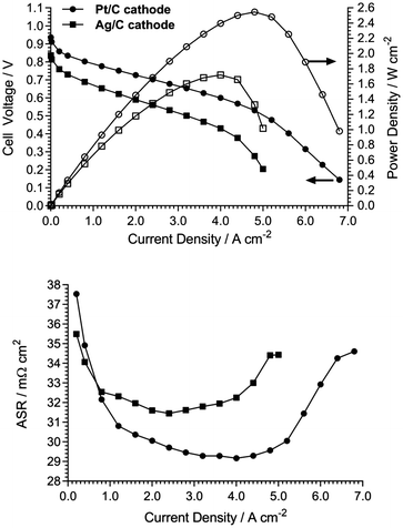 | ||
| Fig. 6 Comparison of HDPE-AEM-containing H2/O2 AEMFC performances at 80 °C with cathodes containing a Pt/C catalyst (40 wt% Pt, 0.4 mg cm−2 Pt loading) and a Ag/C catalyst (40 wt% Ag, 0.85 mg cm−2 Ag loading). All other MEA and cell test parameters as in Fig. 4.4 ASRs were measured using the 850E tester's internal current interrupt method. | ||
These results represent a notable improvement over other recent important literature reports.4 For example, Maurya et al. tested a new polyfluorene quaternary ammonium ionomer with a 30 μM thick TPN AEM (a partially fluorinated polyphenylene-type with long alkyl side-chain),17 which achieved a H2/O2 AEMFC performance at 80 °C of 1.5 W cm−2 using similar catalysts; this AEMFC type showed high stability for 250 h when discharged at 0.6 V at 80 °C, after which cell voltage degradation was observed. There has also been a recent conference report by Wang and Yan et al. of a poly(aryl piperidinium) (PAP) AEM that shows no degradation when immersed in aqueous KOH (1 mol dm−3) for 2000 h at 100 °C;18 this AEM yielded an AEMFC performance of 920 mW cm−2 at 95 °C with low-Pt electrodes, which showed in situ durability over a period of 300 h when discharged at 500 mA cm−2.19 This theme of producing AEMS that are chemically stable in extreme alkali environments follows on from the work by Holdcroft et al.,20 who showed that a poly(arylene-imidazolium) AEM showed minimal degradation in aqueous KOH (10 mol dm−3) at 100 °C. For a comprehensive review of AEMFC performances achieved in other studies published from before 2018, please refer to the review by Dekel.21 It is clear that there is a dearth of 500+ h in situ durability data in the literature, but with many promising alkali stable AEMs being reported, this situation is likely to soon change.
In summary, a new high-density polyethylene-based radiation-grafted anion-exchange membrane (HDPE-AEM) was developed. The switch from using low density polyethylene (LDPE) to using HDPE as a precursor film directly led to enhanced performance characteristics when the AEM was tested in a single-cell anion-exchange membrane fuel cell (AEMFC). The improved performance is hypothesized to be due to enhanced water transport characteristics, particularly the rapid water transport from the anode to the cathode, caused by the change in the nanomorphology/microstructure of the precursor films used to fabricate the AEMs. This phenomenon will be the focus of detailed future studies.
Conflicts of interest
There are no conflicts to declare.Acknowledgements
This research was funded by the UK's Engineering and Physical Sciences Research Council (grant EP/M014371/1). USC gratefully acknowledges the financial support of the U.S. Department of Energy Office of Energy Efficiency & Renewable Energy (award number Award Number: DE-EE0008433) and for the effort expended by X. P. and W. E. M. who produced the validation fuel cell performance data, the crucial durability data, and critically helped with the preparation of the manuscript.References
- (a) A. G. Wright, J. Fan, B. Britton, T. Weissbach, H.-F. Lee, E. A. Kitching, T. J. Peckham and S. Holdcroft, Energy Environ. Sci., 2016, 9, 2130 RSC; (b) Y. Yan, B. Xu, J. Wang and Y. Zhao, US. Pat., 62/314008, 2016 Search PubMed; (c) J. S. Olsen, T. H. Pham and P. Jannasch, Adv. Funct. Mater., 2018, 28, 1702758 CrossRef; (d) H. Peng, Q. Li, M. Hu, L. Xiao, J. Lu and L. Zhuang, J. Power Sources, 2018, 390, 165 CrossRef CAS; (e) S. Gottesfeld, D. R. Dekel, M. Page, C. Bae, Y. Yan, P. Zelenay and Y. S. Kim, J. Power Sources, 2018, 375, 170 CrossRef CAS.
- L. Wang, J. J. Brink, Y. Liu, A. M. Herring, J. Ponce-Gonzalez, D. K. Whelligan and J. R. Varcoe, Energy Environ. Sci., 2017, 10, 2154 RSC.
- (a) X. Peng, T. J. Omasta, E. Magliocca, L. Wang, J. R. Varcoe and W. E. Mustain, Angew. Chem., Int. Ed., 2019, 48, 1046 CrossRef PubMed; (b) X. Peng, V. Kashyap, B. Ng, S. Kurungot, L. Wang, J. R. Varcoe and W. E. Mustain, Catalysts, 2019, 9, 264 CrossRef.
- L. Wang, M. Bellini, H. A. Miller and J. R. Varcoe, J. Mater. Chem. A, 2018, 6, 15404 RSC.
- (a) M. Mamlouk, J. A. Horsfall, C. Williams and K. Scott, Int. J. Hydrogen Energy, 2012, 37, 11912 CrossRef CAS; (b) T. A. Sherazi, J. Y. Sohn, Y. M. Lee and M. D. Guiver, J. Membr. Sci., 2013, 441, 148 CrossRef CAS; (c) R. Espiritu, B. T. Golding, K. Scott and M. Mamlouk, J. Mater. Chem. A, 2017, 5, 1248 RSC.
- (a) V. Sproll, T. J. Schmidt and L. Gubler, Polym. Int., 2016, 65, 174 CrossRef CAS; (b) R. Espiritu, B. T. Golding, K. Scott and M. Mamlouk, J. Power Sources, 2018, 375, 373 CrossRef CAS; (c) F. Ranogajec, Radiat. Chem. Phys., 2007, 76, 1381 CrossRef CAS.
- L. Wang, E. Maggliocca, E. L. Cunningham, W. E. Mustain, S. D. Poynton, R. Escudero-Cid, M. M. Nasef, J. Ponce-Gonzalez, R. Bance-Souahli, R. C. T. Slade, D. K. Whelligan and J. R. Varcoe, Green Chem., 2017, 19, 831 RSC.
- N. Ziv and D. R. Dekel, Electrochem. Commun., 2018, 88, 109 CrossRef CAS.
- Y. Zheng, U. Ash, R. P. Pandey, A. G. Ozioko, J. Ponce-González, M. Handl, T. Weissbach, J. R. Varcoe, S. Holdcroft, M. W. Liberatore, R. Hiesgen and D. R. Dekel, Macromolecules, 2018, 51, 3264 CrossRef CAS.
- T. J. Omasta, A. M. Park, J. M. LaManna, Y. Zhang, X. Peng, L. Wang, D. L. Jacobson, J. R. Varcoe, D. S. Hussey, B. S. Pivovar and W. E. Mustain, Energy Environ. Sci., 2018, 11, 551 RSC.
- T. J. Omasta, L. Wang, X. Peng, C. A. Lewis, J. R. Varcoe and W. E. Mustain, J. Power Sources, 2018, 375, 205 CrossRef CAS.
- V. Sproll, G. Nagy, U. Gasser, J. P. Embs, M. Obiols-Rabasa, T. J. Schmidt, L. Gubler and S. Balog, Macromolecules, 2016, 49, 4253 CrossRef CAS.
- Y. Zhao, K. Yoshimura, H. Shishitani, S. Yamaguchi, H. Tanaka, S. Koizumi, N. Szekely, A. Radulescu, D. Richtere and Y. Maekawa, Soft Matter, 2016, 12, 1567 RSC.
- B. Pivovar, Advanced Ionomers & MEAs for Alkaline Membrane Fuel Cells: report for the 2017 US Department of Energy Hydrogen and Fuel Cells Program Review, 2017, Phoenix AZ, USA.
- (a) H. Erikson, A. Sarapuu and K. Tammeveski, ChemElectroChem, 2019, 6, 73 CrossRef CAS; (b) Y.-M. Zhao, L.-M. Liao, G.-Q. Yu, P.-J. Wei and J.-G. Liu, ChemElectroChem, 2019, 6, 1754 CrossRef CAS; (c) J. Woo, S. Y. Yang, Y. J. Sa, W.-Y. Choi, M.-H. Lee, H.-W. Lee, T. J. Shin, T.-Y. Kim and S. H. Joo, Chem. Mater., 2018, 30, 6684 CrossRef CAS; (d) M. M. Hossen, K. Artyushkova, P. Atanassov and A. Serov, J. Power Sources, 2018, 375, 214 CrossRef CAS; (e) H. Ren, Y. Wang, Y. Yang, X. Tang, Y. Peng, H. Peng, L. Xiao, J. Lu, H. D. Abruña and L. Zhuang, ACS Catal., 2017, 7, 6485 CrossRef CAS; (f) Y. J. Sa, D.-J. Seo, J. Woo, J. T. Lim, J. Y. Cheon, S. Y. Yang, J. M. Lee, D. Kang, T. J. Shin, H. S. Shin, H. Y. Jeong, C. S. Kim, M. G. Kim, T.-Y. Kim and S. H. Joo, J. Am. Chem. Soc., 2016, 138, 15046 CrossRef CAS PubMed.
- https://www.bullionbypost.co.uk (4 PM 25th January 2019).
- S. Maurya, S. Noh, I. Matanovic, E. J. Park, C. N. Villarrubia, U. Martinez, J. Han, C. Bae and Y.-S. Kim, Energy Environ. Sci., 2018, 11, 3283 RSC.
- Y. Yan, abstract 1751, presented at the Anion Exchange Membrane Fuel Cell 1 session of the 233rd Electrochemical Society Meeting, Seattle USA, May, 2018.
- J. Wang, Y. Zhao, B. P. Setzler, S. Rojas-Carbonell, C. B. Yehuda, A. Amel, M. Page, L. Wang, K. Hu, L. Shi, S. Gottesfeld, B. Xu and Y. Yan, Nat. Energy, 2019 DOI:10.1038/s41560-019-0372-8.
- J. Fan, A. G. Wright, B. Britton, T. Weissbach, T. J. G. Skalski, J. Ward, T. J. Peckham and S. Holdcroft, ACS Macro Lett., 2017, 6, 1089 CrossRef CAS.
- D. R. Dekel, J. Power Sources, 2018, 375, 158 CrossRef CAS.
Footnotes |
| † All of the raw data generated by the University of Surrey is freely available (CC-BY) from DOI: 10.15126/surreydata.8050274 |
| ‡ Note an important initial observation that we have made. RG-AEM-based MEAs can currently be fabricated to produce high power densities or tailored for high in situ durabilities. It is evident that new MEA architectures will be required to produce a desirable sweet-spot that yield an optimal, acceptable balance of power output performance and in situ durability (such a lengthy materials engineering effort is beyond the scope of this initial materials development study). |
| This journal is © The Royal Society of Chemistry 2019 |

