 Open Access Article
Lyotropic ‘hairy’ TiO2 nanorods
Fei
Cheng
 a,
Emanuele
Verrelli
a,
Fahad A.
Alharthi
ab,
Stephen M.
Kelly
a,
Emanuele
Verrelli
a,
Fahad A.
Alharthi
ab,
Stephen M.
Kelly
 *a,
Mary
O'Neill
*c,
Neil T.
Kemp
 a,
Stuart P.
Kitney
 d,
Khue T.
Lai
e,
Georg H.
Mehl
 a and
Thomas
Anthopoulos
fg
aSchool of Mathematics & Physical Sciences, University of Hull, Cottingham Road, Hull, HU6 7RX, UK. E-mail: s.m.kelly@hull.ac.uk
bDepartment of Chemistry, College of Science, King Saud University, P.O. Box 2455, Riyadh 11451, Saudi Arabia
cSchool of Science & Technology, Nottingham Trent University, 50 Shakespeare Street, Nottingham, NG1 3LL, UK
dPolar OLED, University of Hull, Cottingham Road, Hull, HU6 7RX, UK
eElectronic Systems Design Centre, Energy Safety Research Institute, College of Engineering, Swansea University Bay Campus, Swansea, SA1 8EN, UK
fCentre for Plastic Electronics & Department of Physics, Blackett Laboratory, Imperial College, London SW7 2BW, UK
gDivision of Physical Sciences and Engineering, King Abdullah University of Science and Technology (KAUST), Thuwal 23955-6900, Saudi Arabia
First published on 17th August 2018
Abstract
We report the synthesis of the first stable, solution-processable and photocrosslinkable hybrid organic/inorganic titanium dioxide nanorods as ‘hairy rods’ coated with phosphonate ligands with photoreactive coumarin groups located in a terminal position. The relationships between the chemical structure of the diethyl-ω-[(7-oxycoumaryl)-n-alkyl]phosphonate ligands on the ligand exchange rate (LER) and the solubility of the resultant ligand-stabilized titanium dioxide nanorods in organic solvents are elucidated. These TiO2 nanorods, with an organic ligand coating, are short enough (aspect ratio = 5–8) to be dissolved in chlorobenzene at high concentrations, but long enough to form lyotropic nematic liquid crystals. These colloidal solutions are used to deposit a thin, uniform layer of hybrid organic/inorganic TiO2 nanorods with their long axes in the plane of a flat, smooth substrate through a self-organization process. Standard photolithographic patterning creates an insoluble dielectric layer of the desired thickness, smoothness and uniformity and with a dielectric constant of sufficient magnitude, k = 8, suitable for the fabrication of multilayer, plastic electronic devices using solution-based fabrication techniques, such as ink-jet printing, used in roll-to-roll manufacturing.
Introduction
Plastic electronics, based on solution-processable and printable electronic devices, are entering the semiconductor market place and are developing into a significant disruptive technology. Indeed, they may not just replace current commercial electronic devices, but also open completely new markets. These plastic electronic devices, such as flat panel displays, Organic Light-Emitting Diodes (OLEDs), Organic Field Effect Transistors (OFETs), Organic Photovoltaics (OPVs), RFID tags, etc., are based on flexible, low-weight and mechanically robust substrates. Their low-cost, roll-to-roll manufacturing processes require the sequential formation of multi-layered uniform thin films of organic semiconductors, metal oxide semiconductors and/or dielectrics, conducting polymers or metallic colloids.1–4 However, the intermixing of adjacent layers deposited in sequence from solution by processes, such as inkjet printing, drop casting, spin coating, doctor blade techniques, etc., is a significant problem with respect to the successful fabrication and subsequent performance of plastic electronic devices. Orthogonal solvents can be used to deposit a series of layers,5,6 but this approach becomes problematic as the number of layers increases as this process limits the choice of materials that can be deposited in sequential steps. Alternatively, multi-layered structures have been achieved by thermally crosslinking semiconducting polymers7 or by thermal annealing to remove solubilizing groups from nanoparticles of metal oxide semiconductors. For example, thermally crosslinked layers of titanium dioxide (TiO2) and surface-modified barium titanium dioxide (BaTiO3) nanoparticles, dispersed in polyvinylphenol for deposition and crosslinking, have been fabricated as dielectric layers for pentacene OFETs.8 Unfortunately, high annealing temperatures are incompatible with flexible substrates and low-cost, high-throughput, roll-to-roll manufacturing processes.Insoluble thin films can also be formed by ultraviolet irradiation of photopolymerisable materials to form insoluble polymer networks. An example of this approach involves the attachment of a photoactive moiety, such as an acrylate, methacrylate or oxetane group, via an aliphatic spacer to a small molecule organic semiconductor.9–13 A significant advantage of this approach is the capability to spatially pattern device features with sub-micron resolution using photolithographic techniques, e.g., organic semiconductors for organic light-emitting diodes and transistors.14,15 Unfortunately, the photopolymerisation reactions proceed via free radical or ionic reactions and require photoinitiators to form a network of polymer chains. These factors can lead to the formation of an inhomogeneous layer, containing radicals or ions that disrupts the electrical performance and stability of electronic devices incorporating such polymer network films.
Solution-processable materials with a high dielectric constant, k, exhibit the potential to replace silicon dioxide as a gate dielectric in plastic electronic devices. Nanoscale forms of titanium dioxide (TiO2) are very important in this context.16–21 The high dielectric constants of its anatase phase (k = 31) and rutile phase (k = ∼114)22 render titanium dioxide a very promising material for application in hybrid organic/inorganic photovoltaic devices23 and non-volatile memory devices with resistive switching.24
The surface of titanium dioxide nanoparticles, including nanorods, must be functionalized with an organic ligand or surfactant in order to overcome the strong adhesion forces between the nanoparticles in order to render them soluble in common organic solvents and, hence, processable from solution.25 The presence of organic, flexible ligands, consisting of long aliphatic chains, stabilizes the surface of inorganic nanoparticles and simultaneously inhibits their aggregation and agglomeration.26 Such ligands offer the potential for additional functionality by the incorporation of photo-dimerisable and crosslinkable, rather than photopolymerisable, groups, for example. This approach is potentially a much more sophisticated approach and offers a higher degree of spatial control and resolution than, for example, the photopolymerisation of the acrylate host of TiO2 nanoparticles dispersed in an organic matrix containing a photoinitiator.27
A range of methods have been used to prepare TiO2 nanorods, such as hydrothermal and solvothermal processing, templating, electrospinning and solution-phase reactions.28–35 Ligand-stabilized TiO2 nanorods have been synthesized using a range of non-hydrolytic methods.35 A one-step, low-temperature method has been used to synthesise oleic acid-capped TiO2 nanorods in the anatase phase using the hydrolysis of titanium tetraisopropoxide (Ti(OiPr)4) and oleic acid as the surfactant with tertiary amines or quaternary ammonium hydroxides as catalysts.34 Solution-processable anatase TiO2 nanorods have been synthesised in a two-step, non-hydrolytic condensation reaction of TiCl4 and Ti(OiPr)4 in the presence of oleic acid.35 Similar non-hydrolytic condensation reactions in the presence of trioctylphosphine oxide and dodecylamine yield anatase titanium dioxide nanorods.28 Oleic acid-capped titanium dioxide nanorods have also been prepared from Ti(OiPr)4 at elevated reaction temperatures.36,37 Uniform anatase TiO2 nanoparticles were prepared using the phase transformation of a Ti(OH)4 gel matrix in the presence of shape-controllers.38 Non-hydrolytic solvothermal reactions have also been used to synthesise oleic acid-capped, solution-processable TiO2 nanorods.39,40 The authors are not aware of any photodimerisable and crosslinkable ligands used to prepare such solution-processable TiO2 nanorods.
We report here the synthesis and processing of the first stable, solution-processable and photo-dimerisable and crosslinkable, mixed ligand-stabilized titanium dioxide nanorods and their use as patterned, insoluble and intractable thin films with a high dielectric constant suitable as dielectric layers in multilayer electronic devices, such as organic field effect transistors (OFETs). New diethyl-ω-[(7-oxycoumaryl)-n-alkyl]phosphonate ligands with photodimerisable coumarin side chains are synthesized and undergo ligand exchange with oleic acid-capped titanium dioxide nanorods. We chose coumarin as the photoactive groups, since light irradiation of thin films of polymethacrylates with coumarin side chains leads to photodimerisation and crosslinking without any free radical or ionic side reactions.12–15,41 The lyotropic liquid crystalline properties of solutions of these TiO2 nanorods, short enough to be soluble and long enough to self-assemble, should facilitate the formation of uniform thin layers with the long axes of the nanorods in the plane of the device substrate. These nanorod domains would provide a uniform flat surface for subsequent layer deposition, after being rendered insoluble by photochemical crosslinking with UV irradiation.
Experimental
Synthesis of the photocrosslinkable TiO2 nanorods 4a & 4b (n = 6) and 4c–f (n = 11)
The reaction scheme for the preparation of the hybrid titanium dioxide nanorods 4a & 4b (n = 6) and 4c–f (n = 11) is shown in Scheme 1 and Fig. 1. The oleic acid-stabilized titanium dioxide nanorods 1 (TiO2–OA) were prepared using hydrolysis of titanium(IV) isopropoxide (TTIP) in the presence of aqueous trimethylamine N-oxide (TMAO) and oleic acid (OA) according to a modified literature procedure.33,34,42 New phosphonate ligands 3 (n = 6 and n = 11) with coumarin side chains were synthesized from the corresponding ω-bromoalkyl-substituted intermediates 2 (n = 6 and n = 11) by means of Michaelis–Arbuzov rearrangement.43,44 The ligands incorporate a phosphonate moiety to bind strongly to TiO2 surfaces.45–47 The ligands 3 (n = 6 and n = 11) possess a coumarin functional group in a terminal position suitable for further photocrosslinking reactions after their attachment to the titanium dioxide nanoparticle surfaces.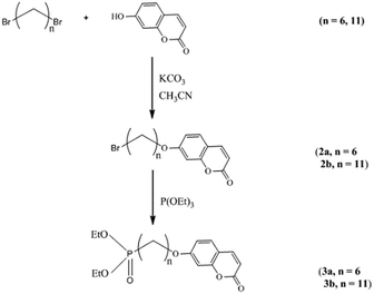 | ||
| Scheme 1 Synthesis of the photoreactive diethyl-ω-[(7-oxycoumaryl)alkyl]phosphonate ligands 3 (n = 6 and n = 11). | ||
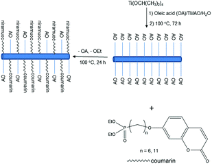 | ||
| Fig. 1 Method of preparation of the mixed ligand-stabilized, anatase titanium dioxide nanorods 4a & 4b (n = 6) and 4c–f (n = 11). | ||
Titanium(IV) tetra-isopropoxide (TTIP, ≥97.0%), oleic acid (OA, 90%), trimethylamine N-oxide (TMAO, 98%), 7-hydroxycoumarin (99%), 1,6-dibromohexane (96%), 1,11-dibromoundecane (≥98.0%), trimethyl phosphite (90%), and trimethylamine (≥99.0%) were sourced from Sigma-Aldrich. Acetonitrile (99.9%) was sourced from VWR Chemicals. Other chemicals and solvents were obtained from Fisher. Ultrapure water with a specific resistance of 18.2 MΩ cm was obtained by reversed osmosis followed by ion exchange and filtration (UPQ PS system, ELGA, USA). All reactions were carried out under an inert atmosphere unless otherwise stated.
The mixed ligand-stabilized, anatase titanium dioxide nanorods 4a & 4b (n = 6) and 4c–f (n = 11) were formed using ligand-exchange reactions between the oleic acid-stabilized titanium dioxide nanorods 1 (TiO2–OA) and the diethyl-ω-[(7-oxycoumaryl)alkyl]phosphonate ligands 3 (n = 6 and 11, respectively), as shown in Fig. 1.
Characterization methods
Fourier transform infrared (FTIR) spectra of the synthesized materials in the form of powders were recorded on a Nicolet Magna-500 FTIR spectrometer. A Bruker IFS 66/S FTIR spectrometer equipped with a water-cooled glowbar source, a potassium bromide (KBr) beam splitter and a deuterated triglycine sulphate detector was used to measure the transmittance of the thin films on a KBr substrate at room temperature. The KBr substrate spectrum was taken under the same conditions as each sample measurement in order to eliminate any inherent artifacts. The resolution was 2 cm−1 and 1000 scans were combined and averaged to produce each FTIR spectrum. The sample compartment was continuously purged with anhydrous air to reduce absorptions due to atmospheric water vapor and carbon dioxide.1H NMR and 31P NMR spectroscopy were carried out using a JEOL Eclipse 400 MHz spectrometer. Deuterated chloroform with an internal standard of tetramethylsilane (TMS) was typically used as the solvent.
Mass spectra were obtained using an Agilent 1100 series HPLC coupled with a Bruker HCT Ultra ion trap MS/MS instrument with an electrospray ion source. The capillary voltage was 3.5 kV, the gas temperature 300 °C and the gas flow 10 L min−1. A acetonitrile/water mixture was used as solvent flowing at 0.3 mL min−1.
Transmission electron microscopy (TEM) was carried out using a Jeol 2010 TEM running at 200 kV and a Gatan Ultrascan 4000 digital camera. The liquid sample was mixed in a vial, a 5 μL aliquot is placed on a hydrophilic carbon coated copper grid and allowed to air dry.
X-ray powder diffraction (XRD) analyses were performed using a SIEMENS D5000 instrument.
The concentration of the titanium and phosphorus present in the samples was determined using an inductively coupled Perkin Elmer plasma 40 emission (ICP) instrument. The concentration of carbon, hydrogen and nitrogen was analyzed using a Fisons EA 1108 CHN apparatus.
Thermogravimetric analyses (TGA) were performed on a Netzsch TGA TG209 thermal balance. UV crosslinking was carried out inside a glovebox at 1 ppm O2, −86 °C dew point using a UV curing lamp (OmniCure 2000, 250–450 nm) with power density of 1.5 W cm−2. Impedance measurements were carried out using a Solartron S1260 with dielectric interface S1296 attached to a probe station and interfaced to a PC using labview.
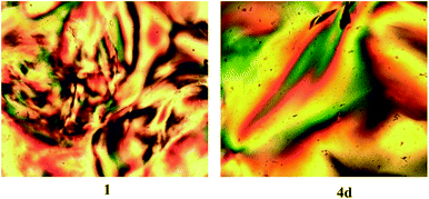
An Olympus BX51 polarizing optical microscope (POM) with a Linkam LTS 350 temperature-controlled stage were utilized to observe the images of the oleic acid-stabilized titanium dioxide nanorods 1 and the ligand-exchanged titanium dioxide nanorods 4d between crossed polarizers.
Synthesis
![[thin space (1/6-em)]](https://www.rsc.org/images/entities/char_2009.gif) :
:![[thin space (1/6-em)]](https://www.rsc.org/images/entities/char_2009.gif) 1 mixture of hexane and diethyl acetate (120 cm3). A white precipitate, formed from the combined washings on standing overnight at −18 °C overnight was filtered off, washed with hexane (120 cm3) and a 1
1 mixture of hexane and diethyl acetate (120 cm3). A white precipitate, formed from the combined washings on standing overnight at −18 °C overnight was filtered off, washed with hexane (120 cm3) and a 1![[thin space (1/6-em)]](https://www.rsc.org/images/entities/char_2009.gif) :
:![[thin space (1/6-em)]](https://www.rsc.org/images/entities/char_2009.gif) 1 mixture of hexane and diethyl acetate (120 cm3) and then dried under vacuum to yield a white solid (12.5 g, 62.6%). 1H NMR (CDCl3): δ 7.64 (d, 1H), 7.37 (d, 1H), 6.84 (m, 2H), 6.26 (d, 1H), 4.03 (t, 2H), 3.44 (t, 2H), 1.83–1.90 (m, 4H), 1.54–1.58 (m, 4H) ppm. IR (KBr pellet, cm−1): 2944, 2862, 1722, 1616, 1556, 1508, 1400, 1292, 1130, 1034, 828, 642. Anal. calcd for C15H17O3Br (%): C, 55.40; H, 5.27. Found: C, 55.68; H, 5.50. MS (m/z): 325, 327 [M + H]+.
1 mixture of hexane and diethyl acetate (120 cm3) and then dried under vacuum to yield a white solid (12.5 g, 62.6%). 1H NMR (CDCl3): δ 7.64 (d, 1H), 7.37 (d, 1H), 6.84 (m, 2H), 6.26 (d, 1H), 4.03 (t, 2H), 3.44 (t, 2H), 1.83–1.90 (m, 4H), 1.54–1.58 (m, 4H) ppm. IR (KBr pellet, cm−1): 2944, 2862, 1722, 1616, 1556, 1508, 1400, 1292, 1130, 1034, 828, 642. Anal. calcd for C15H17O3Br (%): C, 55.40; H, 5.27. Found: C, 55.68; H, 5.50. MS (m/z): 325, 327 [M + H]+.
![[thin space (1/6-em)]](https://www.rsc.org/images/entities/char_2009.gif) :
:![[thin space (1/6-em)]](https://www.rsc.org/images/entities/char_2009.gif) 1 mixture of hexane and diethyl acetate at −18 °C and then purified using flash column chromatography43 (silica gel, methanol
1 mixture of hexane and diethyl acetate at −18 °C and then purified using flash column chromatography43 (silica gel, methanol![[thin space (1/6-em)]](https://www.rsc.org/images/entities/char_2009.gif) :
:![[thin space (1/6-em)]](https://www.rsc.org/images/entities/char_2009.gif) dichloromethane, 10% increased up to 100%) to give the desired product (1.54 g, 26.6%). 1H NMR (CDCl3): δ 7.63 (d, 1H), 7.35 (d, 1H), 6.82 (m, 2H), 6.24 (d, 1H), 4.01 (t, 2H), 3.41 (t, 2H), 1.77–1.89 (m, 4H), 1.30–1.57 (m, 14H) ppm. IR (KBr pellet, cm−1): 2921, 2850, 1732, 1618, 1553, 1512, 1400, 1292, 1138, 1030, 841, 721, 640. Anal. calcd for C20H27O3Br (%): C, 60.76; H, 6.88. Found: C, 60.99; H, 7.08. MS (m/z): 395, 397 [M + H]+.
dichloromethane, 10% increased up to 100%) to give the desired product (1.54 g, 26.6%). 1H NMR (CDCl3): δ 7.63 (d, 1H), 7.35 (d, 1H), 6.82 (m, 2H), 6.24 (d, 1H), 4.01 (t, 2H), 3.41 (t, 2H), 1.77–1.89 (m, 4H), 1.30–1.57 (m, 14H) ppm. IR (KBr pellet, cm−1): 2921, 2850, 1732, 1618, 1553, 1512, 1400, 1292, 1138, 1030, 841, 721, 640. Anal. calcd for C20H27O3Br (%): C, 60.76; H, 6.88. Found: C, 60.99; H, 7.08. MS (m/z): 395, 397 [M + H]+.
![[thin space (1/6-em)]](https://www.rsc.org/images/entities/char_2009.gif) :
:![[thin space (1/6-em)]](https://www.rsc.org/images/entities/char_2009.gif) 1 mixture of hexane and diethyl acetate (20 cm3) was added to the yellow oil and the resultant clear solution cooled at −18 °C overnight to yield a precipitate, which was filtered off, dried under vacuum and finally purified using flash column chromatography43 (silica gel, diethyl acetate
1 mixture of hexane and diethyl acetate (20 cm3) was added to the yellow oil and the resultant clear solution cooled at −18 °C overnight to yield a precipitate, which was filtered off, dried under vacuum and finally purified using flash column chromatography43 (silica gel, diethyl acetate![[thin space (1/6-em)]](https://www.rsc.org/images/entities/char_2009.gif) :
:![[thin space (1/6-em)]](https://www.rsc.org/images/entities/char_2009.gif) dichloromethane, 10% increased up to 100%) to give the desired product (1.68 g, 68.0%). 1H NMR (CDCl3): δ 7.63 (d, 1H), 7.36 (d, 1H), 6.82 (m, 2H), 6.24 (d, 1H), 4.01–4.11 (m, 6H), 1.71–1.8 (m, 6H), 1.47–1.50 (m, 4H), 1.30–1.34 (t, 6H) ppm. 31P NMR (CDCl3): δ 33.1 ppm. IR (KBr pellet, cm−1): 2921, 2850, 1732, 1618, 1553, 1512, 1400, 1292, 1138, 1030, 841, 721, 640. Anal. calcd for C19H27O6P (%): C, 59.68; H, 7.12. Found: C, 59.92; H, 7.39. MS (m/z): 383 [M + H]+, 504 [M + Na]+.
dichloromethane, 10% increased up to 100%) to give the desired product (1.68 g, 68.0%). 1H NMR (CDCl3): δ 7.63 (d, 1H), 7.36 (d, 1H), 6.82 (m, 2H), 6.24 (d, 1H), 4.01–4.11 (m, 6H), 1.71–1.8 (m, 6H), 1.47–1.50 (m, 4H), 1.30–1.34 (t, 6H) ppm. 31P NMR (CDCl3): δ 33.1 ppm. IR (KBr pellet, cm−1): 2921, 2850, 1732, 1618, 1553, 1512, 1400, 1292, 1138, 1030, 841, 721, 640. Anal. calcd for C19H27O6P (%): C, 59.68; H, 7.12. Found: C, 59.92; H, 7.39. MS (m/z): 383 [M + H]+, 504 [M + Na]+.
![[thin space (1/6-em)]](https://www.rsc.org/images/entities/char_2009.gif) :
:![[thin space (1/6-em)]](https://www.rsc.org/images/entities/char_2009.gif) 1 mixture of hexane and diethyl acetate (20 cm3) was added to the yellow oil and the resultant clear solution cooled at −18 °C overnight to yield a precipitate, which was filtered off, washed with a cold 1
1 mixture of hexane and diethyl acetate (20 cm3) was added to the yellow oil and the resultant clear solution cooled at −18 °C overnight to yield a precipitate, which was filtered off, washed with a cold 1![[thin space (1/6-em)]](https://www.rsc.org/images/entities/char_2009.gif) :
:![[thin space (1/6-em)]](https://www.rsc.org/images/entities/char_2009.gif) 1 mixture solution of hexane and diethyl acetate and then dissolved in ethanol (50 cm3) at 50 °C. The precipitate formed on standing overnight at room temperature was filtered off and the filtrate was evaporated down to give a yellow solid. The yellow solid was re-dissolved in ethanol (15 cm3) at 50 °C. The precipitate formed on standing overnight at room temperature was filtered off and the filtrate evaporated down to give the desired product (3.47 g, 60.0% yield). 1H NMR (CDCl3): δ 7.63 (d, 1H), 7.36 (d, 1H), 6.82 (m, 2H), 6.24 (d, 1H), 3.99–4.14 (m, 6H), 1.28–1.72 (m, 26H) ppm. 31P NMR (CDCl3): δ 33.3 ppm. IR (KBr pellet, cm−1): 2978, 2917, 2852, 1727, 1619, 1554, 1511, 1467, 1405, 1292, 1245, 1133, 1030, 953, 839, 727, 615. Anal. calcd for C24H37O6P (%): C, 63.69; H, 8.24. Found: C, 63.46; H, 8.48. MS (m/z): 453 [M + H]+, 475 [M + Na]+.
1 mixture solution of hexane and diethyl acetate and then dissolved in ethanol (50 cm3) at 50 °C. The precipitate formed on standing overnight at room temperature was filtered off and the filtrate was evaporated down to give a yellow solid. The yellow solid was re-dissolved in ethanol (15 cm3) at 50 °C. The precipitate formed on standing overnight at room temperature was filtered off and the filtrate evaporated down to give the desired product (3.47 g, 60.0% yield). 1H NMR (CDCl3): δ 7.63 (d, 1H), 7.36 (d, 1H), 6.82 (m, 2H), 6.24 (d, 1H), 3.99–4.14 (m, 6H), 1.28–1.72 (m, 26H) ppm. 31P NMR (CDCl3): δ 33.3 ppm. IR (KBr pellet, cm−1): 2978, 2917, 2852, 1727, 1619, 1554, 1511, 1467, 1405, 1292, 1245, 1133, 1030, 953, 839, 727, 615. Anal. calcd for C24H37O6P (%): C, 63.69; H, 8.24. Found: C, 63.46; H, 8.48. MS (m/z): 453 [M + H]+, 475 [M + Na]+.
Metal–insulator–metal (MIM) fabrication
Crossbar Metal–Insulator–Metal (MIM) devices were fabricated by spin coating 10% by weight solutions of representative examples of the mixed ligand-stabilized, anatase titanium dioxide nanorods 4a–f onto glass substrates with pre-deposited aluminium bottom electrodes. The top electrodes were then deposited on top of these films (thickness = 200 nm) via remote thermal evaporation with a sample-to-source distance of ca. 400 mm. The high frequency dielectric constant of the materials was extracted from the impedance of the MIM devices using a two-step approach: the resistance R and capacitance C were extracted from the measured impedance using a parallel RC model approximation48 with the extracted C value used to provide an estimate of the film's relative dielectric constant (C = ε0εRA/d where A is the active area of the device and d is the film thickness). The error on these relative dielectric constant values is estimated to be around 5–10%.Results and discussion
Oleic acid-stabilized, anatase titanium dioxide nanorods 1
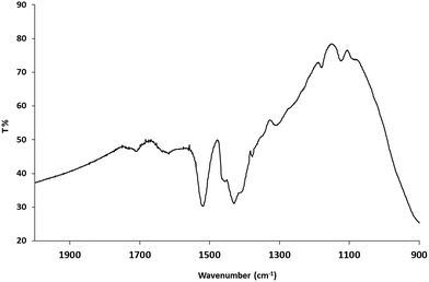
The FTIR spectra of the oleic acid-stabilized, anatase titanium dioxide nanorods 1 show two strong peaks at 1525 cm−1 and 1430 cm−1, see Fig. 2, which can be attributed to antisymmetric and symmetric stretching vibrations of the bidentate COO– group indicating the formation of a complex by coordinating the carboxyl groups of the oleic acid with surface titanium centers dominating the interaction of the ligand with the nanorods surface.49 The frequency difference of Δνa–s = 95 cm−1 between the asymmetric and symmetric stretching vibrations of carboxylate anions indicates the oleic acid molecules are chemically adsorbed onto titanium dioxide surface in a bidentate chelating mode.50 Elemental analyses shows that 18.6% of carbon, 3.2% of hydrogen and 0.36% of nitrogen are present in the oleic acid-stabilized titanium dioxide nanorods 1. The small amount of nitrogen is probably attributable to traces of residual trimethylamine-oxide (TMAO), although the product has been purified many times by dissolving in toluene and precipitating with acetone. ICP analysis indicates the presence of 42.8% titanium in the oleic acid-stabilized titanium dioxide nanorods 1. The weight percent of titanium dioxide is ∼71% based on the titanium content and TGA analysis (800 °C in air).The oleic acid-stabilized titanium dioxide nanorods 1 exhibit an aspect ratio between 5–8, see the XRD and TEM discussion below and therefore, they can be readily dissolved in chlorobenzene to produce stable solutions (at least one month) with the desired concentrations of up to 10 wt% to enable deposition of uniform thin films of the nanorods 1 of the desired thickness from solution using standard wet-chemistry deposition techniques, such as spin coating, drop casting doctor blade techniques, inkjet printing, etc., consistent with roll-to-roll fabrication.
The reaction details and the compositions of the mixed ligand-stabilized titanium dioxide nanorods, 4a, 4b and 4c–f, formed in the ligand-exchange reactions between the oleic acid-stabilized titanium dioxide 1 nanorods and either the diethyl-6-[(7-oxycoumaryl)hexyl]phosphonate ligands 3a or diethyl-11-[(7-oxycoumaryl)undecyl]phosphonate 3b, respectively, are shown in Table 1. The ligand exchange rate (LER), the percentage of oleic acid on titanium dioxide surface replaced by the phosphonate ligands 3a and 3b, calculated based on the ICP and CHN results, increases with reaction time, T, but that the solubility of the resultant hybrid organic/inorganic nanorods 4a–f in chlorobenzene decreases. The LER of the mixed ligand-stabilised titanium dioxide nanorods 4a and 4b produced using the shorter diethyl-6-[(7-oxycoumaryl)hexyl]phosphonate ligand 3a is higher than that of the nanorods 4c–f produced using the longer diethyl-11-[(7-oxycoumaryl)undecyl]phosphonate ligand 3b.
| Sample | Ligand (mg) | t (h) | Ti (%) | P (%) | C (%) | H (%) | N (%) | LERa (%) | Solubilityb (%) |
|---|---|---|---|---|---|---|---|---|---|
| a Percentage of oleic acid remaining on the surface of the nanorods 4a and 4b and the nanorods 4c–f replaced by ligands 3a and 3b, respectively. b Weight-to-weight concentration of the mixed ligand-stabilized, TiO2 nanorods 4a, with an hexyl spacer group, and the corresponding mixed ligand-stabilized, TiO2 nanorods 4d, with an undecyl spacer group, dissolved in chlorobenzene. | |||||||||
| 4a (n = 6) | 40 | 24 | 45.1 | 0.61 | 15.0 | 2.40 | 0.00 | 38.6 | 10 |
| 4b (n = 6) | 40 | 72 | 45.5 | 0.75 | 13.9 | 2.21 | 0.13 | 51.0 | 0 |
| 4c (n = 11) | 30 | 24 | 44.9 | 0.51 | 18.9 | 2.59 | 0.33 | 24.1 | 20 |
| 4d (n = 11) | 30 | 72 | 45.1 | 0.73 | 19.1 | 2.95 | 0.19 | 30.2 | 20 |
| 4e (n = 11) | 30 | 120 | 44.6 | 0.93 | 18.2 | 3.20 | 0.15 | 42.4 | 0 |
| 4f (n = 11) | 60 | 48 | 46.1 | 0.67 | 18.4 | 2.83 | 0.25 | 34.0 | 20 |
As can be seen from Fig. 3, the mixed ligand-stabilised TiO2 nanorods 4a, with a relatively short hexyl spacer group, and the nanorods 4c, 4d and 4f, with a longer undecyl spacer group, with a relatively high LER (38.6%, 24.1%, 30.2% and 34.0%, respectively) dissolve in chlorobenzene at concentrations up to 10 wt% and 20 wt%, respectively. However, the nanorods 4b and 4e, produced using long reactions times (T = 72 h and 120 h, respectively), with a LER value higher than 42%, do not dissolve in chlorobenzene at all.
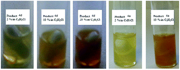 | ||
| Fig. 3 Solutions of the ligand-exchanged, TiO2 nanorods 4a, with a hexyl spacer group, and the corresponding TiO2 nanorods 4d, with an undecyl spacer group, in chlorobenzene. | ||
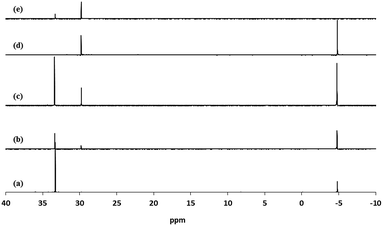
Fig. 4 shows the 31P NMR of diethyl-11-[(7-oxycoumaryl)undecyl]phosphonate ligand 3b and those of the corresponding mixed ligand-stabilized TiO2 nanorods 4c–e before purification and the nanorods 4d after purification. Two peaks at 33.3 and 29.8 ppm can be observed for the mixed ligand-stabilized TiO2 nanorods 4c–e. The peak at 33.3 ppm is characteristic of the ligand 3b, while the new peak at 29.8 ppm is attributable to the bonds between the inorganic TiO2 core and the organic ligand in the mixed ligand-stabilized titanium dioxide nanorods 4c–e. The intensity of the peak at 33.3 ppm decreases with increasing reaction time. This observation provides further supporting evidence that LER increases with increasing reaction time, see Table 1. Free, non-bonded 3b can be completely removed by purification as can be readily elucidated from Fig. 4(d). The new peak at 29.8 ppm is very similar to that of TiO2 modified with octadecylphosphonic acid (ODPA) reported previously,51,52 suggesting that the ethoxy groups have been displaced upon ligand exchange and that of the diethyl-11-[(7-oxycoumaryl)undecyl]phosphonate ligand 3b is bonded to the surface of the TiO2 nanorods by a tridentate attachment.51,52
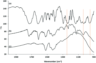
The FTIR spectra of oleic acid-stabilized titanium dioxide 1 nanorods, the diethyl-11-[(7-oxycoumaryl)undecyl]phosphonate ligand 3b and the mixed ligand-stabilized titanium dioxide nanorods 4c, produced by their reaction, are shown in Fig. 5. The IR spectrum of the mixed ligand-stabilized titanium dioxide nanorods 4c, produced in the ligand-exchange reaction, clearly shows many peaks characteristic of the phosphonate ligand 3b. However, the presence of strong peaks at 1525 cm−1 and 1430 cm−1 indicates that only part of oleic acid coating of the oleic acid-stabilized titanium dioxide nanorods 1 nanorods has been replaced by the ligand 3b. The IR spectrum of the ligand 3b shows a P![[double bond, length as m-dash]](https://www.rsc.org/images/entities/char_e001.gif) O stretching band at 1243 cm−1 and a P–O–C absorption band at 952 m−1, as indicated by the pink line. However, these two bands are not present in the mixed ligand-stabilized titanium dioxide nanorods 4c. A broad band attributable PO3 stretching can be observed at about 1060 cm−1, further supporting the conclusion that the ligand 3b is attached to the titanium dioxide surface through a tridentate bonding mode.53
O stretching band at 1243 cm−1 and a P–O–C absorption band at 952 m−1, as indicated by the pink line. However, these two bands are not present in the mixed ligand-stabilized titanium dioxide nanorods 4c. A broad band attributable PO3 stretching can be observed at about 1060 cm−1, further supporting the conclusion that the ligand 3b is attached to the titanium dioxide surface through a tridentate bonding mode.53
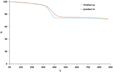
The TGA curves of the ligand-exchanged product the mixed ligand-stabilized titanium dioxide nanorods 4a, with the relatively short hexyl spacer group, and the corresponding mixed ligand-stabilized titanium dioxide nanorods 4d, with a longer undecyl spacer group, are shown in Fig. 6. A major weight loss occurs in the temperature range of 350 °C to 500 °C due to thermal decomposition of the organic ligands. The residues at 950 °C are 75.9% and 75.1% for the mixed ligand-stabilized titanium dioxide nanorods 4a and 4d, with either a hexyl or an undecyl spacer group, respectively.
Analysis of the XRD spectra confirms that these mixed ligand-stabilized titanium dioxide nanorods 4a and 4d both exhibit the anatase phase. The XRD patterns of the ligand-exchanged nanorods 4a and 4d are very similar to that of oleic acid-stabilized titanium dioxide nanorods 1, see Fig. 7, i.e., the ligand exchange reaction does not affect the morphology of the inorganic nanorods. Hence, the TEM images of the ligand-exchanged titanium dioxide nanorods 4a and 4d are also similar to that of oleic acid-stabilized titanium dioxide nanorods 1, see Fig. 8. The combination of the XRD and TEM spectra suggests the ligand exchange reaction, carried out on the oleic acid-stabilized titanium dioxide nanorods 1 at 100 °C to form the ligand-exchanged hybrid inorganic/organic titanium dioxide nanorods 4a and 4d, has very little effect, as could be reasonably expected, on the phase, size and shape and, hence, anisotropy, of the core of TiO2 nanorods with an aspect ratio of 5–8, see Fig. 8. The nanorods 4a–d are 18–23 nm in length and 2.4–3.2 nm in diameter on average. TEM images of these nanorods with a very sparse distribution on the TEM grids indicate that the nanorods exhibit a round cross section (cylindrical shape) rather than a rectangular shape.
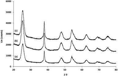 | ||
| Fig. 7 XRD of (a) oleic acid-stabilized TiO2 nanorods 1; (b) and the (c) mixed ligand-stabilized TiO2 nanorods 4d and 4a with either an undecyl or a hexyl spacer group, respectively. | ||
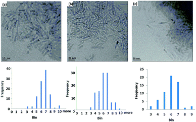 | ||
| Fig. 8 TEM of (a) oleic acid-stabilized TiO2 nanorods 1; (b) and (c) the mixed ligand-stabilized, TiO2 nanorods 4d and 4a with either an undecyl or a hexyl spacer group, respectively. | ||
Samples of the oleic acid-stabilized titanium dioxide nanorods 1 and the ligand-exchanged titanium dioxide nanorods 4d were dissolved in chlorobenzene to produce highly concentrated (20%) solutions (wt/wt) in each case. The chlorobenzene solvent was then allowed to evaporate slowly at room temperature from these solutions and the percentage concentration of the nanorods determined by changes in the weight of the residual solution. The images of these chlorobenzene/nanorod solutions captured using polarizing optical microscopy (POM) at a concentration of 60% (wt/wt) are shown in Fig. 9. Both photomicrographs reveal the presence of birefringent domains containing disclinations at domain boundaries characteristic of the lyotropic liquid crystalline state and, in this case, of a nematic phase. These samples are fluid and can be disturbed by the application of slight physical pressure, which results in ‘flashing’ of the POM images, which is again a typical characteristic of the nematic phase.
Fig. 10 shows POM images of solutions in chlorobenzene of oleic acid-stabilized titanium dioxide nanorods 1 recorded at different concentrations. The image of the nanorod/chlorobenzene colloidal solution at a concentration of 50% (wt/wt) clearly shows the presence of birefringent droplets incorporating four-point brushes typical of the lyotropic nematic state.25 The Schlieren texture equally characteristic of a nematic phase can be clearly observed at a concentration of 60% (wt/wt) for the same sample. The nematic phase texture completely disappears when the concentration of the nanorod/chlorobenzene solution is above 80% (wt/wt), which is appears to be due to crystallization of the nanorods from solution to form a solid.
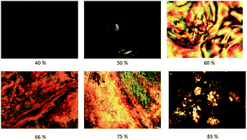 | ||
| Fig. 10 POM images of colloidal solutions of the oleic acid-stabilized TiO2 nanorods 1 at different concentrations (wt/wt) in chlorobenzene. | ||
In order to investigate the dependence of the lyotropic nematic phase on temperature, a solution of the TiO2–OA nanorod 1 in chlorobenzene (60% wt/wt) was drop cast on a glass slide, circled with AP 101 grease and covered with a cover slip. The POM images of these solutions at different temperature are shown in Fig. 11. It can be seen that with increasing temperature, the Schlieren texture of the lyotropic nematic phase is retained, although some small changes in appearance can be observed, as expected due to the fluid nature of the sample. However, the birefringent Schlieren texture of the solution completely disappears above a temperature of ca. 100 °C to form a colorless isotropic liquid. This thermal process is not reversible and the Schlieren texture does not return on cooling the sample below the nematic–isotropic clearing point (N–I) of ca. 100 °C, as would have been expected normally for a liquid crystal transition. However, that this is not the case is due to the evaporation of the chlorobenzene solvent from the sides of the sample at these temperatures. The oleic acid-stabilised TiO2 nanorods 1 slowly crystallize over time out of this solution as shown in the image taken of this sample after five days, see Fig. 11.
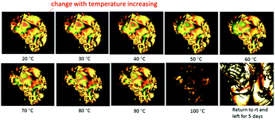 | ||
| Fig. 11 POM image of a solution of the oleic acid-stabilized TiO2 nanorods 1 at concentration of 60% (wt/wt) in chlorobenzene recorded at different temperatures. | ||
Film formation and photochemical crosslinking
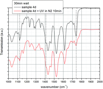
The irradiation of coumarin and its derivatives with appropriate wavelengths of UV light results in photo-dimerization in solution and in thin-films.41,54,55 In order to investigate the crosslinking of the coumarin side chains, bonded onto the surface of the titanium dioxide nanorods via phosphonate groups, the mixed ligand-stabilized titanium dioxide nanorods 4a and 4d, with either a hexyl or an undecyl spacer group, respectively, were deposited by spin casting onto a KBr substrate using standard procedures, allowed to dry and then photoirradiated with UV light at 250–450 nm and an exposure of 900 J cm−2. The FTIR spectra of sample 4d before and after photoirradiation are shown in Fig. 12. The assignment of representative peaks is recorded in Table 2 by comparison with those of similar structures.41,55,56 Several important differences can be clearly observed between the two spectra. Firstly, after exposure of the sample, the carbonyl peak at 1739 cm−1 becomes weaker and broader with a shoulder at about 1769 cm−1, suggesting the modification of the enone conjugation due to loss of conjugation resulting from dimerization.40 The shift to higher wavenumber suggests the formation of head-to-head (H–H) photo-dimers.56 The absorbance of the weak peak at 1405 cm−1 due to the C![[double bond, length as m-dash]](https://www.rsc.org/images/entities/char_e001.gif) C bond decreases upon photoirradiation of the sample, also indicating the 2 + 2 photo-dimerization of coumarin to a cyclobutane derivative. The peak at 1122 cm−1 decreases and the peak at 1159 cm−1 increases due to the loss of enone conjugation in coumarin and formation of the cyclobutane photoproduct. All these changes in peak intensity and shifts indicate that the coumarin side chains in the ligand-exchanged hybrid inorganic/organic TiO2 nanorods 4d have been photochemically crosslinked in a head-to-head (H–H) photo-dimerisation reaction.
C bond decreases upon photoirradiation of the sample, also indicating the 2 + 2 photo-dimerization of coumarin to a cyclobutane derivative. The peak at 1122 cm−1 decreases and the peak at 1159 cm−1 increases due to the loss of enone conjugation in coumarin and formation of the cyclobutane photoproduct. All these changes in peak intensity and shifts indicate that the coumarin side chains in the ligand-exchanged hybrid inorganic/organic TiO2 nanorods 4d have been photochemically crosslinked in a head-to-head (H–H) photo-dimerisation reaction.
| Wavenumber (cm−1) | Assignmenta |
|---|---|
| a Sym. = symmetric and asym. = asymmetric. | |
| 1739 | C![[double bond, length as m-dash]](https://www.rsc.org/images/entities/char_e001.gif) O stretching O stretching |
| 1616 | Ring C![[double bond, length as m-dash]](https://www.rsc.org/images/entities/char_e001.gif) C stretching C stretching |
| 1525 | Bidentate COO– asym. stretching |
| 1464 | CH2 scissor |
| 1430 | Bidentate COO– sym. stretching |
| 1405 |
cis C![[double bond, length as m-dash]](https://www.rsc.org/images/entities/char_e001.gif) C stretching C stretching |
| 1280 | C(C![[double bond, length as m-dash]](https://www.rsc.org/images/entities/char_e001.gif) O)–O asym. stretching O)–O asym. stretching |
| 1230 | ![[double bond, length as m-dash]](https://www.rsc.org/images/entities/char_e001.gif) C–O–C asym. stretching C–O–C asym. stretching |
| 1159 | Unconjugated ester stretching |
| 1122 | C(C![[double bond, length as m-dash]](https://www.rsc.org/images/entities/char_e001.gif) O)–O sym. stretching O)–O sym. stretching |
| 1052 | ![[double bond, length as m-dash]](https://www.rsc.org/images/entities/char_e001.gif) C–O–C sym. stretching and PO3 C–O–C sym. stretching and PO3 |
The solubility of a photoinduced crosslinked thin film of the mixed ligand-stabilized, TiO2 nanorods 4d, with an undecyl spacer group, was tested by exposing the crosslinked films to the solvent (chlorobenzene) used to prepare the lyotropic solutions and monitoring the film thickness before and after washing in the solvent. The film was photoirradiated with light of wavelength 250–450 nm to a total fluence of 200 J cm−2. Chlorobenzene was then spin-coated onto the film at 1000 rpm for 60 s and removed by evaporation. Table 3 shows that the layer thickness is unchanged after this process, demonstrating that crosslinking of the ligands renders the layer of hybrid organic/inorganic nanorods completely insoluble. Smooth homogeneous ‘hairy rod’ films were obtained with thicknesses between 50–400 nm by changing the concentration of the chlorobenzene solutions (2.5% to 20% wt/wt).
| Sample | Film thickness before washing (nm) | Film thickness after washing (nm) |
|---|---|---|
| 4d | 55 ± 5 | 54 ± 4 |
Morphologically, these thin-films show relatively small surface roughness, ∼2–3 nm RMS, and good uniformity over wide areas with peak–valley distances, ∼20 nm, over profiled areas of 1 μm2, as measured by atomic force microscopy (AFM), see Fig. 13. It may be reasonably postulated that, as the chlorobenzene solvent evaporates from these dilute solutions of the mixed ligand-stabilized, TiO2 nanorods 4d to form solutions with higher nanorod concentrations on the substrate surface, then the fluid, but ordered, nature of these highly concentrated lyotropic nematic liquid crystalline solutions, see above, will facilitate the self-organized formation of domains on the substrate surface of these nanorods with their long axes parallel to each other and in the plane of the substrate surface, see Fig. 13. This spontaneous orientation of rods with a relatively high degree of anisotropy (aspect ratio = 5–8) on planar substrate surfaces mirrors that of nematic liquid crystals in Liquid Crystal Displays (LCDs).57
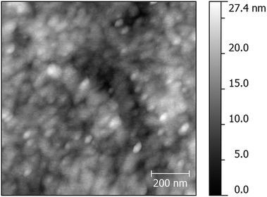 | ||
| Fig. 13 AFM topography of a sample of the mixed ligand-stabilized, TiO2 nanorods 4d deposited on a flat KBr substrate showing an area of 1 μm × 1 μm. | ||
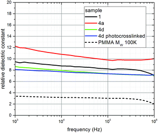
Two main features of the dielectric constant spectra are apparent for the oleic acid-stabilized nanorods 1, the mixed ligand-stabilized, titanium dioxide nanorods 4a and 4d before – and after – photocrosslinking, see Fig. 14. Firstly the value of the relative dielectric constants, k, are all around 10; secondly each spectrum shows a steady increase of the dielectric constant as the frequency is reduced from 1 MHz toward 1 kHz. This results from polarization effects involving the device's interface contribution to the impedance.58 The dielectric constant values obtained for the mixed ligand-stabilized, titanium dioxide nanorods 4d, with an undecyl spacer group, although slightly lower compared to that of the oleic acid-stabilized titanium dioxide nanorods 1, are actually compatible with the corresponding latter values by taking into consideration the above mentioned relative error. On the other hand, the mixed ligand-stabilized, titanium dioxide nanorods 4a, with a hexyl spacer group, show a higher value for the dielectric constant, k, compared to that of the oleic acid-stabilized nanorods 1 and the mixed ligand-stabilized titanium dioxide nanorods 4d, which is due to the lower relative weight of the total ligand component in the film or, equivalently, increased relative weight of the titanium dioxide nanorod component, as compared to the other ligands used. The relatively low value of the effective dielectric constant (k = 8) is due to a combination of two factors. Firstly, the nanocomposite comprises two components, a high-k one attributable to the TiO2 nanorod core and a low-k one attributable to the organic ligand shell. Secondly, the stacking of nanorods in a thin film will inevitably create a volume of void space (k ∼ 1) between the nanorods. It is the average contribution of high-k and low-k components that generates the effective dielectric constant (k ∼ 8) observed for the dielectric films.
No significant changes are observed in the dielectric constant values between ‘as-spun’ devices and the photocrosslinked ones using the titanium dioxide nanorods 4d. Hence, the photochemical crosslinking process, used to render the dielectric layer insoluble, does not change the value of the dielectric constant, which for materials 1 and 4 is ca. three times higher than that of poly-methylmethacrylate (PMMA) a typical and widely used organic dielectric material with applications also in electron beam lithography, see dashed curve in Fig. 14.
The leakage current density was relatively high at 2 × 10⁻⁷ A cm−2 @ 2 V and 2 × 10⁻⁵ A cm−2 @ 4 V. Hence, the dielectric breakdown would occur at 5 V for a crossbar device with 200 nm thick high-k film and electrode area of 10−4 cm2. However, a thickness of 200 nm was considered to be insulating enough to allow a reliable characterization of the dielectric properties of these films.
Conclusions
Two new photoreactive phosphonate ligands 3a and 3b were synthesized by means of a Michaelis–Arbuzov rearrangement and used in ligand exchange reactions with the oleic acid-stabilized titanium dioxide nanorods 1 to produce the hybrid inorganic/organic nanorods 4a–f. An optimized ligand exchange reaction at 100 °C does not change the phase and size of the titanium dioxide nanorods, with a high aspect ratio (5–8), in the resultant hybrid inorganic/organic nanorods 4a–f. The ligand exchange rate (LER) depends on the chemical structure of the organophosphorus ligands, i.e., the phosphonate 3a with a shorter alkyl chain has a higher LER. The hybrid organic/inorganic nanorods with an LER lower than 42% can be readily dissolved in chlorobenzene at high concentration to produce lyotropic nematic liquid crystals. Solution-processed and self-organized, uniform thin films of the nanorods 4a–f, with their long axis in the plane of the substrate due to the liquid crystalline nature of the solutions as they dry on the surface, exhibit a relatively high dielectric constant, suitable for use as the dielectric layer for organic field effect transistors, e.g., with low switching voltage, and one that is three times higher than that of PMMA. UV-photo-dimerization and crosslinking of these hybrid organic/inorganic nanorod dielectric layers renders them insoluble, with no change in the dielectric constant, to facilitate the formation of multilayer plastic electronic devices using wet-chemistry techniques. These new dielectric layers show resistive memory switching, which would facilitate the vertical integration of non-volatile memory devices. The relatively high leakage current, due to the low-energy conduction band, of these layers will be addressed in further work in improved prototype devices.Conflicts of interest
There are no conflicts to declare.Acknowledgements
The research leading to these results has received funding from the EPSRC under the Grant Agreement Number EP/J001597/1. Mrs A Lowry, Mrs C Kennedy and Dr R Knight are thanked for providing TEM, CHN and ICP analyses, respectively. Professor S. K. Haywood and Dr S. I. Rybchenko are thanked for providing access to the Bruker FTIR spectrometer for thin film transmission measurements.Notes and references
- L. Petti, N. Münzenrieder, C. Vogt, H. Faber, L. Büthe, G. Cantarella, F. Bottacchi, T. D. Anthopoulos and G. Tröster, Appl. Phys. Rev., 2016, 3, 021303–021353 Search PubMed.
- Y. S. Rim, S. H. Bae, H. Chen, N. D. Marco and Y. Yang, Adv. Mater., 2016, 28, 4415–4440 CrossRef CAS PubMed.
- K. R. R. Venkata, A. K. Venkata, P. S. Karthik and S. P. Singh, RSC Adv., 2015, 5, 77760–77790 RSC.
- L. Qian, Y. Zheng, J. Xue and P. H. Holloway, Nat. Photon., 2011, 5, 543–548 CrossRef CAS.
- S. Ho, S. Liu, Y. Chen and F. So, J. Photon. Energy, 2015, 5, 057611 CrossRef.
- H. Zhang, H. Li, X. Sun and S. Chen, ACS Appl. Mater. Interfaces, 2016, 8, 5493–5498 CrossRef CAS PubMed.
- G. Wantz, L. Derue, O. Dautel, A. Rivaton, P. Hudhomme and C. Dagron-Lartigau, Polym. Int., 2014, 63, 1346–1361 CrossRef CAS.
- P. Kim, X. H. Zhang, B. Domercq, S. C. Jones, P. J. Hotchkiss, S. R. Marder, B. Kippelen and J. W. Perry, Appl. Phys. Lett., 2008, 93, 013302 CrossRef.
- M. P. Aldred, A. E. A. Contoret, S. R. Farrar, S. M. Kelly, D. Mathieson, M. O'Neill, W. C. Tsoi and P. A. Vlachos, Adv. Mater., 2005, 17, 1368–1372 CrossRef CAS.
- A. E. A. Contoret, S. R. Farrar, P. O. Jackson, S. M. Khan, L. May, M. O'Neill, J. E. Nicholls, S. M. Kelly and G. J. Richards, Adv. Mater., 2000, 12, 971–974 CrossRef CAS.
- C. D. Müller, A. Falcou, N. Reckefuss, M. Rojahn, V. Wiederhirn, P. Rudati, H. O. Frohne Nuyken, H. Becker and K. Meerholz, Nature, 2003, 421, 829–833 CrossRef PubMed.
- M. O'Neill and S. M. Kelly, Adv. Mater., 2003, 15, 1135–1146 CrossRef.
- M. O'Neill and S. M. Kelly, Adv. Mater., 2011, 23, 566–584 CrossRef PubMed.
- A. Liedtke, L. Chunhong, M. O'Neill, P. E. Dyer, S. P. Kitney and S. M. Kelly, ACS Nano, 2010, 4, 3248–3253 CrossRef CAS PubMed.
- I. McCulloch, W. Zhang, M. Heeney, C. Bailey, M. Giles, D. Graham, M. Shkunov, D. Sparrowe and S. Tierney, J. Mater. Chem., 2003, 13, 2436–2444 RSC.
- H. J. Chen, L. Wang and W. Y. Chin, Mater. Chem. Phys., 2007, 101, 12–19 CrossRef CAS.
- U. Gesenhues, Chem. Eng. Technol., 2001, 24, 685 CrossRef CAS.
- M. Fernandez-Garcia, A. Martínez-Arias, J. C. Hanson and J. A. Rodriguez, Chem. Rev., 2004, 104, 4063–4104 CrossRef CAS PubMed.
- V. Samuel, R. Pasricha and V. Ravi, Ceram. Int., 2005, 31, 555–557 CrossRef CAS.
- R. Pelton, X. Geng and M. Brook, Adv. Colloid Interface Sci., 2006, 127, 43–53 CrossRef CAS PubMed.
- A. Wold, Chem. Mater., 1993, 5, 280–283 CrossRef CAS.
- S. Roberts, Phys. Rev., 1949, 76, 1215–1221 CrossRef CAS.
- Z. Wang, Q. Li, Z. She, F. Chen and L. Li, J. Mater. Chem., 2012, 22, 4097–4105 RSC.
- D. H. Kwon, K. M. Kim, J. H. Jang, J. M. Jeon, M. H. Lee, G. H. Kim, X. S. Li, G. S. Park, B. Lee, S. Han, M. Kim and C. S. Hwang, Nat. Nanotechnol., 2010, 5, 148–153 CrossRef CAS PubMed.
- M. Zorn, S. Meuer, M. N. Tahir, Y. Khalavka, C. Soennichsen, W. Tremel and R. Zentel, J. Mater. Chem., 2008, 18, 3050–3058 RSC.
- N. R. Jana, Chem. Commun., 2003, 1950–1951 RSC.
- N. Nakayama and T. Hayashi, Compos. Appl. Sci. Manuf., 2007, 38, 1996–2004 CrossRef.
- U. Vukičević, S. C. Ziemian, A. Bismarck and M. S. P. Shaffer, J. Mater. Chem., 2008, 18, 3448–3453 RSC.
- S. J. Kwon, H. B. Im, J. E. Nam, J. K. Kang, T. S. Hwang and K. B. Yi, Appl. Surf. Sci., 2014, 320, 487–493 CrossRef CAS.
- B. Santara and P. K. Giri, Mater. Chem. Phys., 2013, 137, 928–936 CrossRef CAS.
- S. Biswas, V. Sundstrom and S. De, Mater. Chem. Phys., 2014, 147, 761–771 CrossRef CAS.
- Y. D. Park, K. Anabuki, S. Kim, K. W. Park, D. H. Lee, S. H. Um, J. Kim and J. H. Cho, Macromol. Res., 2013, 21, 636–640 CrossRef CAS.
- G. Y. Teo, M. P. Ryan and D. J. Riley, Electrochem. Commun., 2014, 47, 13–16 CrossRef CAS.
- P. D. Cozzoli, A. Kornowski and H. Weller, J. Am. Chem. Soc., 2003, 125, 14539–14548 CrossRef CAS PubMed.
- R. Menzel, B. F. Cottam, S. Ziemian and M. S. P. Shaffer, J. Mater. Chem., 2012, 22, 12172–12178 RSC.
- J. Joo, S. G. Kwon, T. Yu, M. Cho, J. Lee, J. Yoon and T. Hyeon, J. Phys. Chem. B, 2005, 109, 15297–15302 CrossRef CAS PubMed.
- Z. Zhang, X. Zhong, S. Liu, D. Li and M. Han, Angew. Chem., Int. Ed. Engl., 2005, 117, 3532–3536 CrossRef.
- T. Sugimoto, X. Zhou and A. Muramatsu, J. Colloid Interface Sci., 2003, 259, 53–56 CrossRef CAS PubMed.
- A. S. Susha, A. A. Lutich, C. Liu, H. Xu, R. Zhang, Y. Zhong, K. S. Wong, S. Yang and A. L. Rogac, Nanoscale, 2013, 5, 1465–1469 RSC.
- Y. Han, L. Wu, H. Gu, H. Chen and Z. Zhang, J. Mater. Sci.: Mater. Electron., 2013, 24, 1220–1224 CrossRef CAS.
- M. Obi, S. Morino and K. Ichimura, Chem. Mater., 1999, 11, 656–664 CrossRef CAS.
- G. Caputo, R. Cingolani and P. D. Cozzoli, Phys. Chem. Chem. Phys., 2009, 11, 3692–3700 RSC.
- D. S. Pedersen and C. Rosenbohm, Synthesis, 2001, 16, 2431–2434 Search PubMed.
- A. K. Bhattacharya and G. Thyagarajan, Chem. Rev., 1981, 81, 415–430 CrossRef CAS.
- G. Guerrero, P. H. Mutin and A. Vioux, Chem. Mater., 2001, 13, 4367–4373 CrossRef CAS.
- P. Falaras, I. M. Arabatzis, T. Stergiopoulos, G. Papavassiliou and M. Karagianni, J. Mater. Process. Technol., 2005, 161, 276–281 CrossRef CAS.
- W. Gao, L. Dickinson, C. Grozinger, F. G. Morin and L. Reven, Langmuir, 1996, 12, 6429–6435 CrossRef CAS.
- E. H. Nicollian and J. R. Brews, MOS Physics and Technology, New York, Wiley, 1982 Search PubMed.
- P. J. Thistlethwaite and M. S. Hook, Langmuir, 2000, 16, 4993–4998 CrossRef CAS.
- M. Nara, H. Torii and M. Tasumi, J. Phys. Chem., 1996, 100, 19812–19817 CrossRef CAS.
- W. Gao, L. Dickinson, C. Grozinger, F. G. Morin and L. Reven, Langmuir, 1996, 12, 6429–6643 CrossRef CAS.
- A. Maliakal, H. Katz, P. M. Cotts, S. Subramoney and M. Peter, J. Am. Chem. Soc., 2005, 127, 14655–14662 CrossRef CAS PubMed.
- J. Randon, P. Blanc and R. Paterson, J. Membr. Sci., 1995, 98, 119–129 CrossRef CAS.
- H. Morrison, H. Curtis and T. McDowell, J. Am. Chem. Soc., 1966, 88, 5415–5419 CrossRef CAS.
- P. O. Jackson, M. O'Neill, D. L. Duffy, P. Hindmarsh, S. M. Kelly and G. J. Owen, Chem. Mater., 2001, 13, 694–703 CrossRef CAS.
- W. Li, V. Lynch, H. Thompson and M. A. Fox, J. Am. Chem. Soc., 1997, 119, 7211–7217 CrossRef CAS.
- M. O'Neill and S. M. Kelly, J. Phys. D: Appl. Phys., 2000, 33, R67–R84 CrossRef.
- E. Barsoukov and J. R. Macdonald, in Impedance Spectroscopy: Theory, Experiment, and Applications, Wiley-Interscience, Hoboken, New Jersey, USA, 2nd edn, 2005, p. 595 Search PubMed.
| This journal is © The Royal Society of Chemistry 2019 |

