Dual carbon-modified nickel sulfide composites toward high-performance electrodes for supercapacitors†
Jiapeng
He
a,
Can
Guo
a,
Shaowen
Zhou
a,
Yinlong
Zhao
a,
Qingpeng
Wang
b,
Shun
Yang
*a,
Jiaqin
Yang
*c and
Qinghong
Wang
 *a
*a
aSchool of Chemistry and Materials Science, Jiangsu Normal University, Xuzhou 221116, China. E-mail: wangqh@jsnu.edu.cn; yangshun@jsnu.edu.cn
bInstitute of Biopharmaceutical Research, Liaocheng University, Liaocheng 252059, China
cSchool of Chemistry and Chemical Engineering, Qufu Normal University, Qufu 273165, China. E-mail: yjq8681@163.com
First published on 20th November 2018
Abstract
Composites with reduced graphene oxide (rGO) modification or carbon-coated structures are usually constructed to enhance the electrochemical performance of electrode materials. Herein, we develop a sequential freeze-drying, calcination and sulfidation strategy to prepare dual carbon-modified nickel sulfide composites (Ni3S2@C/rGO). Owing to the ultrasmall particle size, stable structure and high electrical conductivity, the as-prepared composites exhibit enhanced performance with high specific capacitance (1023.44 F g−1 at a current density of 5 A g−1), good rate capability (848 F g−1 at a current density of 20 A g−1) and long-term cycling stability (70.1% retention over 5000 cycles) as electrode materials for supercapacitors. Moreover, the asymmetric supercapacitor displays a good cycle life and a superior energy density of 52.5 W h kg−1 at a power density of 750 W kg−1. The facile fabrication and excellent electrochemical performances of Ni3S2@C/rGO demonstrate that constructing dual carbon-modified composites is a promising strategy for high-performance electrode materials.
Introduction
With the rapid consumption of fossil fuels and serious deterioration of the environment, various clean and renewable energy sources have drawn much attention. As one of the most promising energy storage devices, supercapacitors (SCs) have been widely investigated owing to the advantages of high power density, low cost, fast charging capability, excellent cycling stability and good environment benignity.1–3 Among various electrode materials, metal oxides/sulfides (NiO, Ni(OH)2, MnO2, NiCo2S4etc.)4–7 are reported to have potential application. Nickel sulfides, such as NiS, NiS2, Ni3S2, and Ni3S4 have attracted increasing attention owing to their high theoretical capacitances, rich redox chemistry, low cost and nature abundance.8–12 Specially, Ni3S2 is reported to have excellent performance in supercapacitors.13 Unfortunately, the intrinsically poor conductivity and large volume change occurring during a charge/discharge process lead to rapid capacitance fading and poor rate capability.With an aim to address the above problems, numerous approaches have been rationally developed to improve the electrochemical performance, such as tailoring the size of the nanoparticles,14 designing micro-nano structures15 and preparing composites.16–20 It is worth noting that designing and preparing carbon-modified composites is an effective approach to improve the electrochemical properties of SCs.21–24 As we all know, with the advantages of light weight, high conductivity and high surface area, graphene is preferred to produce high conductivity and abundant active sites for redox reactions.25–27 Moreover, carbon coating has also been employed to improve the conductivity in electrical devices.28–30 The capsule structure not only shortens the electron diffusion path, but also avoids the reunion of nanoparticles and prevents the polysulfide from dissolving, resulting in excellent electrochemical performance. Therefore, double carbon-modified structures are expected to improve the electrochemical performances. For example, Chen et al.14 prepared (Co9S8 QD@HCP)@rGO sponge-like composites by simultaneous thermal reduction, carbonization, and sulfidation processes. Wang et al.31 synthesized graphene encapsulated hollow FeP@carbon nanocomposites (H-FeP@C@GR). Han et al.32 reported a type of sandwich-type CoS-based coaxial nanocable with a conductive CNT backbone core, well-confined CoS nanoparticle interlayer and a conformal carbon coating shell (denoted as CNT@CoS@C). When the above dual carbon-modified composites were used as anodes for sodium/lithium ion batteries, they all exhibited outstanding electrochemical performance, which was a benefit from the conductive network, structural integrity, and the synergistic effect of each component.
Herein, we report a simple three-step method to fabricate dual carbon-modified Ni3S2@C/rGO composites. The introduction of graphene networks endows the ultrasmall Ni3S2 nanoparticles with favourable dispersion and enhanced conductivity, thus accelerating electron transport and ion diffusion reactions. Furthermore, the carbon coating layer plays an important role in alleviating the volume expansion of Ni3S2, resulting in long-term cycling with high capacity retention rates. In addition, the rGO and carbon layers play a synergistic effect for avoiding aggregation of Ni3S2 nanoparticles during the charge/discharge process. While used as an electrode for supercapacitors, Ni3S2@C/rGO delivers excellent cycling stability and good rate properties. It is demonstrated that the dual carbon-modified method is an effective strategy to improve the electrochemical performance of electrode materials.
Experimental
Synthesis of NiO@C/rGO precursors
A dual carbon-modified nickel oxide composite was synthesized by a freeze-drying method, followed by an annealing process. The typical process was as follows: 0.02 g of graphene oxide (GO) was dispersed in 50 mL of deionized water under stirring, and then 0.3 g of Ni(NO3)2·6H2O and 0.3 g of citric acid were added into the above mixture. After stirring for 30 min, the blended solution was freeze-dried under vacuum for 48 hours. After that, the above sample was calcined under argon for 2 h at 450 °C to obtain NiO@C/rGO precursors. For comparison, Ni/rGO was prepared under the same conditions without the addition of citric acid. The NiO@C composite was also prepared without the addition of GO.Synthesis of Ni3S2@C/rGO
Ni3S2@C/rGO was obtained via a sulfidation of NiO@C/rGO. Typically, 50 mg of the as-obtained NiO@C/rGO precursor was dispersed in 35 mL of deionized water by sonication, followed by the addition of 1.0 g Na2S·9H2O under vigorous stirring. Then the suspension was transferred into 50 mL Teflon lined stainless steel autoclaves for hydrothermal reaction at 120 °C for 10 h. Finally, the precipitates were washed with deionized water and ethanol several times and dried at 60 °C overnight, and the Ni3S2@C/rGO composite was obtained. For comparison, Ni3S2/rGO and Ni3S2@C composites were also prepared under the same conditions with Ni/rGO and NiO@C as precursors, respectively.Material characterization
The crystallographic characterization of the samples was done by powder X-ray diffraction (XRD, Bruker, D8 ADVANCE powder diffractometer, Cu Kα radiation, λ = 0.15418 nm). The morphologies were characterized by field emission scanning electron microscopy (SEM, Hitachi, SU-8010) linked with X-ray energy-dispersive spectroscopy (EDS, EDAX PW9900), and transmission electron microscopy (TEM, FEI, Tecnai G20). X-ray photoelectron spectroscopy (XPS) was conducted on a VG Multilab 2000 (VG Inc.) photoelectron spectrometer using monochromatic Al Kα radiation under vacuum at 2 × 10⁻⁶ Pa. The thermal behavior of the as-prepared samples has been investigated by the thermogravimetric analyzer-derivative thermogravimetry technique (TGA-Q500). The specific surface areas and porous features of the samples were further investigated by nitrogen adsorption/desorption measurements (Autosorb-IQ2-VP).Electrochemical measurements
The working electrodes were fabricated by mixing active material (Ni3S2@C/rGO, Ni3S2/rGO or Ni3S2@C), acetylene black and a binder (PVDF) in a weight ratio of 80![[thin space (1/6-em)]](https://www.rsc.org/images/entities/char_2009.gif) :
:![[thin space (1/6-em)]](https://www.rsc.org/images/entities/char_2009.gif) 10
10![[thin space (1/6-em)]](https://www.rsc.org/images/entities/char_2009.gif) :
:![[thin space (1/6-em)]](https://www.rsc.org/images/entities/char_2009.gif) 10. The formed paste was pressed on a piece of nickel foam (1.0 cm × 1.0 cm) at 2 MPa, and dried under vacuum at 80 °C for 10 h. Electrochemical measurements were conducted in a three-electrode arrangement in 2 M KOH electrolyte. A platinum sheet and HgO/Hg electrode were used as the counter electrode and reference electrode, respectively. Cyclic voltammetry (CV) was conducted with a Zahner IM6 electrochemical workstation with voltage scan rates of 1, 2, 5 and 10 mV s−1. The galvanostatic charge–discharge tests were conducted on a LAND battery system at the current densities of 1, 2, 5, 10, and 20 A g−1. The specific capacitance is calculated according to the following equation:
10. The formed paste was pressed on a piece of nickel foam (1.0 cm × 1.0 cm) at 2 MPa, and dried under vacuum at 80 °C for 10 h. Electrochemical measurements were conducted in a three-electrode arrangement in 2 M KOH electrolyte. A platinum sheet and HgO/Hg electrode were used as the counter electrode and reference electrode, respectively. Cyclic voltammetry (CV) was conducted with a Zahner IM6 electrochemical workstation with voltage scan rates of 1, 2, 5 and 10 mV s−1. The galvanostatic charge–discharge tests were conducted on a LAND battery system at the current densities of 1, 2, 5, 10, and 20 A g−1. The specific capacitance is calculated according to the following equation: | (1) |
 | (2) |
 | (3) |
Results and discussion
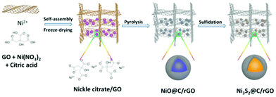
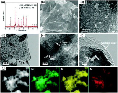
The schematic illustration for the fabrication of dual carbon-modified Ni3S2@C/rGO is shown in Fig. 1 and the specific details are described in the Experimental section. The whole formation process of the dual carbon-modified Ni3S2@C/rGO is mainly based on three stages: freeze-drying, calcination and sulfidation. At the initial stage of freeze-drying, a 3D GO network structure was formed by self-assembly, meanwhile, nickel citrate was formed and anchored on GO sheets by electrostatic interaction. Subsequently, nickel citrate and excessive citric acid were decomposed during the calcination process, leading to the formation of NiO with a carbon coating structure and the reduction of GO. As a result, uniform NiO@C nanoparticles anchored on rGO (see ESI Fig. S1†) were prepared and employed as precursors. As shown in Fig. S1a,† the diffraction peaks are mainly indexed to Ni (JCPDS no. 70-989) and partially indexed to NiO (JCPDS no. 73-1519). From the SEM and TEM images (Fig. S1b–e†), the nanoparticles display a diameter of 20–30 nm and uniformly embed in the rGO matrix. Fig. S1f† shows that the NiO nanoparticles are encapsulated by amorphous carbon. Therefore, the NiO@C/rGO precursor already has a dual carbon-modified structure. Subsequently, ion exchange reaction occurs during the following sulfidation process, converting NiO@C/rGO into Ni3S2@C/rGO.The crystal structure of Ni3S2@C/rGO was examined by XRD. As shown in Fig. 2a, the diffraction peaks at 21.8°, 31.2°, 37.8°, 44.4°, 49.8°, 50.3° and 55.3° are assigned to the (010), (−110), (111), (020), (120), (−120) and (−211) crystal planes of rhombohedral Ni3S2 (JCPDS no. 71-1682), respectively. Meanwhile, impurity diffraction peaks of NiS (JCPDS no. 3-760) with low intensities are also observed. The morphology of Ni3S2@C/rGO is shown in Fig. 2b and c. It can be seen that Ni3S2 nanoparticles with a small size of 20–30 nm uniformly disperse and tightly anchor on the conductive rGO networks. The low magnification TEM image shown in Fig. 2d further confirms the aforementioned observation. HRTEM images shown in Fig. 2e and f present a clear lattice spacing of 0.28 nm, 0.41 nm and 0.24 nm corresponding to the (−110), (010) and (111) planes of Ni3S2, respectively, indicating excellent crystallinity. From Fig. 2f, it is clearly seen that Ni3S2 nanoparticles are enwrapped by an amorphous carbon shell with a thickness of ∼5 nm, which is formed by the decomposition of citric acid. In addition, EDS mapping has been carried out to demonstrate the distribution of elements. Obviously, the atoms of Ni, S and C distribute uniformly in the composite (Fig. 2g). This dual carbon-modified structure will greatly enhance the conductivity of the Ni3S2 electrode materials, and will further be beneficial for the improvement of the electrochemical performances.
XPS was conducted to determine the surface electronic states and chemical composition of Ni3S2@C/rGO. The survey spectrum shown in Fig. 3a shows that four elements of Ni 2p, S 2p, C 1s and O 1s exist in the as-prepared Ni3S2@C/rGO composite. The element O may be derived from rGO or decomposition of oxygen-containing groups in citric acid during the pyrolysis process.28 As shown in Fig. 3b, the two peaks at approximately 855.8 eV and 873.2 eV in the high-resolution Ni 2p spectrum can be assigned to Ni 2p3/2 and Ni 2p1/2, respectively. The Ni 2p spectrum can be fitted with two spin–orbit dual characteristics of Ni2+ and Ni3+, corresponding to the oxidation state of Ni in Ni3S2 and NiS.9,33 The peaks located at 861.7 eV and 879.6 eV correspond to the satellite peaks.34,35 The S 2p spectrum displays characteristic peaks of S 2p3/2 and S 2p1/2 at about 159.9 eV and 162.4 eV, respectively (Fig. 3c). In the C 1s spectrum (Fig. 3d), the peaks appearing at 284.6 eV and 285.4 correspond to the C![[double bond, length as m-dash]](https://www.rsc.org/images/entities/char_e001.gif) C and C–C bonds, which exist in rGO and the pyrolytic carbon. A peak at 286.2 eV is obviously detected, which can be assigned to the C–O configuration, confirming the existence of oxygenated functional groups in the dual carbon decoration.36
C and C–C bonds, which exist in rGO and the pyrolytic carbon. A peak at 286.2 eV is obviously detected, which can be assigned to the C–O configuration, confirming the existence of oxygenated functional groups in the dual carbon decoration.36
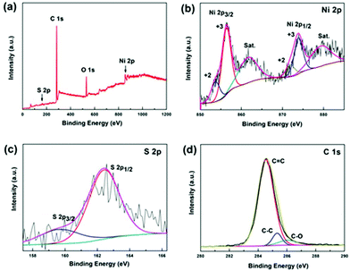 | ||
| Fig. 3 XPS spectra of the Ni3S2@C/rGO composite: (a) full spectrum, (b) Ni 2p, (c) S 2p and (d) C 1s. | ||
In order to verify the effect of the dual carbon-modified structure on the electrochemical properties, Ni3S2/rGO and Ni3S2@C composites were obtained for comparison using Ni/rGO and NiO@C as precursors. In Fig. S2a,† the as-prepared Ni/rGO sample exhibits high purity, which is consistent with JCPDS no. 70-1869. Fig. S2b–d† show that metal Ni nanoparticles with small sizes uniformly distribute on rGO sheets. For the NiO@C precursor, both peaks of Ni (JCPDS no. 70-1869) and NiO (JCPDS no. 71-1179) diffusion peaks are observed (Fig. S3a†). The NiO particles coated by carbon display a good distribution, which is confirmed by Fig. S3b–d.† Through the sulfidation process, Ni3S2/rGO and Ni3S2@C composites were obtained. As shown in Fig. 4a, the sharp diffraction peaks indicate well the degree of crystallinity of Ni3S2/rGO, and the crystal lattice shown in Fig. 4d also demonstrates it. In the Ni3S2/rGO composite, Ni3S2 nanoparticles with an ultrasmall size of ∼20 nm uniformly distribute and tightly anchor on the rGO conductive substrate (Fig. 4b and c). As for Ni3S2@C, it exhibits a weak degree of crystallinity with a low diffraction peak intensity as shown in Fig. 4e. Impurity diffraction peaks of NiS (JCPDS no. 3-760) are also found for both of Ni3S2/rGO and Ni3S2@C, similar to Ni3S2@C/rGO. Fig. 4f–h shows that Ni3S2@C is composed of amorphous carbon coated Ni3S2 nanoparticles with a diameter of ∼10 nm, which is smaller than Ni3S2/rGO and Ni3S2@C/rGO.
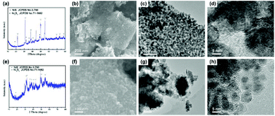 | ||
| Fig. 4 (a) XRD pattern, (b) SEM image and (c, d) TEM images of Ni3S2/rGO, and (e) XRD pattern, (f) SEM image and (g, h) TEM images of the Ni3S2@C composite. | ||
TGA of Ni3S2@C/rGO, Ni3S2/rGO and Ni3S2@C composites in air was conducted from room temperature to 800 °C. As shown in Fig. S4,† slight weight loss in the initial stage results from the removal of water and residual organics. Approximately 57.8%, 86.3% and 66.8% of the original sample weight remained after TGA in air and the resultant solid combustion product is NiO.27 The overall reaction is given in eqn (4).
| 2Ni3S2 + 7O2 = 6NiO + 4SO2 | (4) |
Therefore, the Ni3S2 content in Ni3S2@C/rGO, Ni3S2/rGO and Ni3S2@C was estimated to be 61.9%, 92.3% and 71.6%, respectively. Besides, the specific surface area and porous characteristics of the samples are characterized through N2 adsorption–desorption measurements, which are shown in Fig. S5.† It can be found that the specific surface area of Ni3S2@C (170.2 m2 g−1) is higher than that of Ni3S2@C/rGO (144.2 m2 g−1) and Ni3S2/rGO (58.5 m2 g−1). The results demonstrate that the introduction of amorphous carbon can greatly improve the specific surface area of Ni3S2@C/rGO.
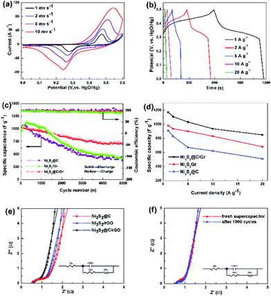
The typical cyclic voltammetry (CV) curves of Ni3S2@C/rGO at sweep rates ranging from 1 to 10 mV s−1 are presented in Fig. 5a. The observed pair of redox peaks indicates the existence of faradaic redox reactions between Ni2+/Ni3+ and OH− during the electrochemical process, which is shown as follows:37,38
| Ni3S2 + 3OH− = Ni3S2(OH)3 + 3e− | (5) |
Moreover, the CV curves measured with variable scan rates display similarly shapes without any obvious distortion, confirming its pseudocapacitance characteristic and good electrochemical reversibility. In addition, the galvanostatic charge–discharge curves of the Ni3S2@C/rGO electrode collected at different current densities show the platform nearly at 0.35/0.45 V (Fig. 5b), which is well consistent with the CV observations. In comparison, Ni3S2/rGO (Fig. S6a†) and Ni3S2@C (Fig. S6b†) electrodes show similar charge/discharge curves, but much lower capacitances. Furthermore, a comparison of the cyclic voltammetry (CV) curves at different scan rates is shown in Fig. S7a–c.† The integral areas of the CV curves illustrate that the Ni3S2@C/rGO electrode displays significantly enhanced electrochemical performance compared with Ni3S2/rGO and Ni3S2@C. Based on the CV curves, the redox peak current follows well a power-law relationship with the scan rate (Ip = aνb), where a b-value of 0.5 indicates that the redox reaction of Ni3S2 electrodes can be observed as a diffusion-controlled battery-type faradaic process.7
Long cycling stability is also a significant factor for supercapacitors. Repeated charging/discharging measurement at a current density of 5 A g−1 is conducted to further evaluate the electrochemical properties. As shown in Fig. 5c, it is noted that the Ni3S2@C/rGO electrode presents good cycling stability after 5000 cycles compared with Ni3S2/rGO and Ni3S2@C. The initial discharge capacitance of Ni3S2@C/rGO is about 1023.44 F g−1, and the specific capacitance remains at 724.32 F g−1 and after that, repeated charging/discharging proceeds 5000 times, with a capacity retention ratio of 70.1%. While for Ni3S2/rGO and Ni3S2@C, there is a short activation process at the initial charge/discharge stage, followed by sharp capacitance degradation with retention ratios of 51.9% and 45.0%, respectively. The rate capabilities of the Ni3S2@C/rGO, Ni3S2/rGO and Ni3S2@C electrodes measured at 1, 2, 5, 10 and 20 A g−1 are shown in Fig. 5d and Table S1.† Obviously, it can be seen that the Ni3S2@C/rGO electrode delivers the highest specific capacitance of 1171 F g−1 at 1 A g−1, whereas only 980 F g−1 and 910 F g−1 are obtained for Ni3S2/rGO and Ni3S2@C, respectively. Upon increasing the high current density to 20 A g−1, the Ni3S2@C/rGO electrode can still retain a large specific capacitance of 848 F g−1, demonstrating good rate capability. Electrochemical impedance spectroscopy (EIS) was further conducted to investigate the redox reaction kinetics of the Ni3S2@C/rGO, Ni3S2/rGO and Ni3S2@C electrodes. As shown in Fig. 5e, a semicircle in the high-frequency region and a straight line in the low-frequency region are obviously observed, which are related to the charge transfer resistance (Rct) and the capacitive behavior of the electrode, respectively.39,40 The Rct of Ni3S2@C/rGO, Ni3S2/rGO and Ni3S2@C electrodes are 0.21, 0.24 and 0.25 Ω, respectively, demonstrating that the introduction of rGO and the carbon layer accelerates the electron transfer reaction kinetics. Furthermore, the line in the low frequency of Ni3S2@C/rGO is more vertical than Ni3S2/rGO and Ni3S2@C that confirms the ideal capacitive behavior of the Ni3S2@C/rGO electrode.41 It is observed that even after 1000 cycles at 5 A g−1, the Ni3S2@C/rGO electrode displays a similar EIS curve to the freshly prepared electrode (Fig. 5f), illustrating the excellent stability of the electrode.
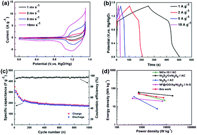
To evaluate the practical application of the Ni3S2@C/rGO composite, an asymmetric supercapacitor (ASC) has been fabricated employing commercial activated carbon (AC) as the negative electrode with a working potential window of 1.5 V in 2 M KOH. The CV curves of the AC electrode display nearly rectangular shape, showing typical electric double-layer capacitance properties (Fig. S8a†). As shown in Fig. S8b,† the AC electrode delivers an average specific capacitance of 167 F g−1 at 5 A g−1 with a high coulombic efficiency of ∼99%. To balance the charge between the positive and negative electrodes, the optimum loading mass ratio of Ni3S2@C/rGO![[thin space (1/6-em)]](https://www.rsc.org/images/entities/char_2009.gif) :
:![[thin space (1/6-em)]](https://www.rsc.org/images/entities/char_2009.gif) AC is about 1
AC is about 1![[thin space (1/6-em)]](https://www.rsc.org/images/entities/char_2009.gif) :
:![[thin space (1/6-em)]](https://www.rsc.org/images/entities/char_2009.gif) 3. Fig. 6a shows the CV profiles of Ni3S2@C/rGO//AC ASC at various scan rates of 1–10 mV s−1. The redox peaks of each CV curve indicate the faradaic pseudocapacitive nature of Ni3S2@C/rGO//AC.16,17 When the scan rate increases, the redox peaks shift slightly and remain stable, demonstrating fast charging and discharging characteristics. According to the galvanostatic charge–discharge curves, the specific capacitance of Ni3S2@C/rGO//AC is calculated to be 168, 138, 113 and 100 F g−1 at 1, 2, 5 and 10 A g−1, respectively, showing a good rate performance. Fig. 6c shows the cycling stability of the Ni3S2@C/rGO//AC ASC. The specific capacitance still remains at 166.8 F g−1 after 1000 cycles. The power performance of Ni3S2@C/rGO//AC is also evaluated in the Ragone plot. As shown in Fig. 6d, Ni3S2@C/rGO//AC delivers an energy density of 52.5 W h kg−1 at a power density of 750 W kg−1 and a power density of 7500 W kg−1 at an energy density of 31.25 W h kg−1, which are equal or higher than those previously reported nickel sulfide electrode materials.17,42–44
3. Fig. 6a shows the CV profiles of Ni3S2@C/rGO//AC ASC at various scan rates of 1–10 mV s−1. The redox peaks of each CV curve indicate the faradaic pseudocapacitive nature of Ni3S2@C/rGO//AC.16,17 When the scan rate increases, the redox peaks shift slightly and remain stable, demonstrating fast charging and discharging characteristics. According to the galvanostatic charge–discharge curves, the specific capacitance of Ni3S2@C/rGO//AC is calculated to be 168, 138, 113 and 100 F g−1 at 1, 2, 5 and 10 A g−1, respectively, showing a good rate performance. Fig. 6c shows the cycling stability of the Ni3S2@C/rGO//AC ASC. The specific capacitance still remains at 166.8 F g−1 after 1000 cycles. The power performance of Ni3S2@C/rGO//AC is also evaluated in the Ragone plot. As shown in Fig. 6d, Ni3S2@C/rGO//AC delivers an energy density of 52.5 W h kg−1 at a power density of 750 W kg−1 and a power density of 7500 W kg−1 at an energy density of 31.25 W h kg−1, which are equal or higher than those previously reported nickel sulfide electrode materials.17,42–44
The excellent electrochemical performance of the dual carbon-modified Ni3S2@C/rGO electrode can be attributed to the following effects: (i) the small size of Ni3S2 can facilitate the fast reaction kinetics and boost the effective surface area of the active material, resulting in high specific capacity; (ii) TEM images of the electrodes after 1000 cycles at 5 A g−1 confirm that the quite stable nanostructure does favor the good cycling performance of the Ni3S2@C/rGO composite (Fig. S9†). On one hand, the uniform and tight distribution of Ni3S2 anchored on rGO can not only benefit electron transfer, but also protect Ni3S2 nanoparticles from aggregation during cycling (Fig. S9a†). On the other hand, the capsule structure of Ni3S2 formed by carbon coating further prevents the aggregation and dissolution of Ni3S2 during the charging/discharging process (Fig. S9b†); (iii) the dual carbon-modified structure significantly improves the conductivity of the active materials, thus helping to enhance the rate performance of the electrodes. Therefore, the realization of the dual carbon-modified nanostructure can greatly generate remarkable electrochemical performance of the Ni3S2@C/rGO electrode.
Conclusions
In summary, dual carbon-modified Ni3S2@C/rGO electrode materials have been prepared by sequential freeze-drying, calcination and sulfidation processes. The unique dual carbon-modified structure effectively protects the aggregation of Ni3S2 nanoparticles, constructs integral conductive networks and buffers the volume change of active materials during a charge/discharge process. Benefiting from the ultrasmall particle size, good conductivity and stable nanostructure, the as-prepared Ni3S2@C/rGO electrode exhibits superior electrochemical performance for supercapacitors with an outstanding cycle life and rate performance (with the specific capacitance of 1023.44 F g−1 at 5 A g−1 retaining 70.1% after 5000 cycles). The Ni3S2@C/rGO//AC ASC also delivers satisfactory energy density and power density, demonstrating its potential in practical application. In addition, this work opens a new avenue for improving the electrochemical performance of electrode materials.Conflicts of interest
There are no conflicts to declare.Acknowledgements
This work is supported by the Natural Science Foundation of Jiangsu Province (BK20160213, BK20170239), the National Natural Science Foundation of China (51702138), the Postgraduate Research & Practice Innovation Program of Jiangsu Province (KYCX18-2106) and the Scientific Research Foundation of Qufu Normal University (xkj201601).Notes and references
- J. Yan, Q. Wang, T. Wei and Z. Fan, Adv. Energy Mater., 2014, 4, 1300816 CrossRef.
- G. Yu, X. Xie, L. Pan, Z. Bao and Y. Cui, Nano Energy, 2013, 2, 213–234 CrossRef CAS.
- H. Wang, B. Zhu, W. Jiang, Y. Yang, W. R. Leow, H. Wang and X. Chen, Adv. Mater., 2014, 26, 3638–3643 CrossRef CAS.
- H. Sun, Z. Ma, Y. Qiu, H. Liu and G. Gao, Small, 2018, 14, 1800294 CrossRef PubMed.
- Q. Ke, C. Guan, X. Zhang, M. Zheng, Y. W. Zhang, Y. Cai, H. Zhang and J. Wang, Adv. Mater., 2017, 29, 1604164 CrossRef PubMed.
- G. Yu, L. Hu, M. Vosgueritchian, H. Wang, X. Xie, J. R. Mcdonough, X. Cui, Y. Cui and Z. Bao, Nano Lett., 2011, 11, 2905–2911 CrossRef CAS PubMed.
- B. Y. Guan, L. Yu, X. Wang, S. Song and X. W. Lou, Adv. Mater., 2017, 29, 1605051 CrossRef PubMed.
- Y. Li, K. Ye, K. Cheng, J. Yin, D. Cao and G. Wang, J. Power Sources, 2015, 274, 943–950 CrossRef CAS.
- S. S. Rao, D. Punnoose, J.-H. Bae, I. K. Durga, C. V. Thulasi-Varma, B. Naresh, A. Subramanian, V. Raman and H.-J. Kim, Electrochim. Acta, 2017, 254, 269–279 CrossRef.
- Z. Dai, X. Zang, J. Yang, C. Sun, W. Si, W. Huang and X. C. Dong, ACS Appl. Mater. Interfaces, 2015, 7, 25396 CrossRef CAS PubMed.
- P. Wu, D. Wang, J. Ning, J. Zhang, X. Feng, J. Dong and Y. Hao, J. Alloys Compd., 2018, 731, 1063–1068 CrossRef CAS.
- Y. Zhang, W. Sun, X. Rui, B. Li, H. T. Tan, G. Guo, S. Madhavi, Y. Zong and Q. Yan, Small, 2015, 11, 3694–3702 CrossRef CAS PubMed.
- F. Chen, S. Ji, Q. Liu, H Wang, H. Liu, D. J. L. Brett, G. Wang and R. Wang, small, 2018, 14, 1800791 CrossRef PubMed.
- Z. Chen, R. Wu, M. Liu, H. Wang, H. Xu, Y. Guo, Y. Song, F. Fang, X. Yu and D. Sun, Adv. Funct. Mater., 2017, 27, 1702046 CrossRef.
- P. Zhang, B. Y. Guan, L. Yu and X. W. Lou, Angew. Chem., Int. Ed., 2017, 56, 7141–7145 CrossRef CAS PubMed.
- R. Li, S. Wang, J. Wang and Z. Huang, Phys. Chem. Chem. Phys., 2015, 17, 16434–16442 RSC.
- W. He, C. Wang, H. Li, X. Deng, X. Xu and T. Zhai, Adv. Energy Mater., 2017, 7, 1700983 CrossRef.
- L. Huang, H. Hou, B. Liu, K. Zeinu, X. Zhu, X. Yuan, X. He, L. Wu, J. Hu and J. Yang, Appl. Surf. Sci., 2017, 425, 879–888 CrossRef CAS.
- X. Zou, Q. Sun, Y. Zhang, G.-D. Li, Y. Liu, Y. Wu, L. Yang and X. Zou, Sci. Rep., 2018, 8, 4478 CrossRef PubMed.
- S. Yu, Y. Zhang, G. Lou, Y. Wu, X. Zhu, H. Chen, Z. Shen, S. Fu, B. Bao and L. Wu, Sci. Rep., 2018, 8, 5246 CrossRef PubMed.
- T. Zhu, H. B. Wu, Y. Wang, R. Xu and X. W. Lou, Adv. Energy Mater., 2012, 2, 1497–1502 CrossRef CAS.
- P. Hao, J. Tian, Y. Sang, C. C. Tuan, G. Cui, X. Shi, C. P. Wong, B. Tang and H. Liu, Nanoscale, 2016, 8, 16292–16301 RSC.
- S. Dai, B. Zhao, C. Qu, D. Chen, D. Dang, B. Song, B. M. deGlee, J. Fu, C. Hu, C. P. Wong and M. Liu, Nano Energy, 2017, 33, 522–531 CrossRef CAS.
- A. Majeed, P. Hou, S. Jiang, J. Li, L. Ping, G. Li, F. Zhang, C. Liu and H. Cheng, J. Mater. Chem. A, 2017, 5, 24813–24819 RSC.
- J. Yang, X. Duan, W. Guo, D. Li, H. Zhang and W. Zheng, Nano Energy, 2014, 5, 74–81 CrossRef CAS.
- Q. Pan, J. Xie, T. Zhu, G. Cao, X. Zhao and S. Zhang, Inorg. Chem., 2014, 53, 3511–3518 CrossRef CAS PubMed.
- A. A. Abdelhamid, X. Yang, J. Yang, X. Chen and J. Y. Ying, Nano Energy, 2016, 26, 425–437 CrossRef CAS.
- X. Zhao, H.-E. Wang, R. C. Massé, J. Cao, J. Sui, J. Li, W. Cai and G. Cao, J. Mater. Chem. A, 2017, 5, 7394–7402 RSC.
- J. Wang, D. Cao, G. Yang, Y. Yang and H. Wang, J. Solid State Electrochem., 2017, 21, 3047–3055 CrossRef CAS.
- T. Liu, C. Jiang, B. Cheng, W. You and J. Yu, J. Mater. Chem. A, 2017, 5, 21257–21265 RSC.
- X. Wang, K. Chen, G. Wang, X. Liu and H. Wang, ACS Nano, 2017, 11, 11602–11616 CrossRef CAS PubMed.
- F. Han, C. Zhang, B. Sun, W. Tang, J. Yang and X. Li, Carbon, 2017, 118, 731–742 CrossRef CAS.
- J. Li, S. Wang, T. Xiao, X. Tan, P. Xiang, L. Jiang, C. Deng, W. Li and M. Li, Appl. Surf. Sci., 2017, 420, 919–926 CrossRef CAS.
- Z. Li, X. Yu, A. Gu, H. Tang, L. Wang and Z. Lou, Nanotechnology, 2017, 28, 065406 CrossRef PubMed.
- C. Tang, C. Zang, J. Su, D. Zhang, G. Li, Y. Zhang and K. Yu, Appl. Surf. Sci., 2011, 257, 3388–3391 CrossRef CAS.
- P. Chen, T. Xiao, Y. Qian, S. Li and S. Yu, Adv. Mater., 2013, 25, 3192–3196 CrossRef CAS PubMed.
- E. Kamali-Heidari, Z. Xu, M. H. Sohi, A. Ataie and J. Kim, Electrochim. Acta, 2018, 271, 507–518 CrossRef CAS.
- Z. Li, B. Li, C. Liao, Z. Liu, D. Li, H. Wang and Q. Li, Electrochim. Acta, 2017, 253, 344–356 CrossRef CAS.
- X. Li, R. Ding, W. Shi, Q. Xu and E. Liu, Chem. – Eur. J., 2017, 23, 6896–6904 CrossRef CAS PubMed.
- Y. Yuan, J. Lin, D. Zhang, S. Yin, Y. Zhao, J. Yang, Y. Chen and S. Guo, Electrochim. Acta, 2017, 227, 303–309 CrossRef CAS.
- J. Yang, X. Duan, Q. Qin and W. Zheng, J. Mater. Chem. A, 2013, 1, 7880–7884 RSC.
- W. Fu, Y. Zhao, J. Mei, F. Wang, W. Han, F. Wang and E. Xie, Electrochim. Acta, 2018, 283, 737–743 CrossRef CAS.
- J. Qi, Y. Chang, Y. Sui, Y. He, Q. Meng, F. Wei, Y. Ren and Y. Jin, Adv. Mater. Interfaces, 2017, 5, 1700985 CrossRef.
- L. Ye, L. Zhao, H. Zhang, P. Zan, S. Gen, W. Shi, B. Han, H. Sun, X. Yang and T. Xu, J. Mater. Chem. A, 2016, 5, 1603–1613 RSC.
Footnote |
| † Electronic supplementary information (ESI) available. See DOI: 10.1039/c8qi01024b |
| This journal is © the Partner Organisations 2019 |

